EP1433944A1 - Atmospheric pressure detector of internal combustion engine - Google Patents
Atmospheric pressure detector of internal combustion engine Download PDFInfo
- Publication number
- EP1433944A1 EP1433944A1 EP02779903A EP02779903A EP1433944A1 EP 1433944 A1 EP1433944 A1 EP 1433944A1 EP 02779903 A EP02779903 A EP 02779903A EP 02779903 A EP02779903 A EP 02779903A EP 1433944 A1 EP1433944 A1 EP 1433944A1
- Authority
- EP
- European Patent Office
- Prior art keywords
- intake
- atmospheric pressure
- internal combustion
- combustion engine
- pressures
- Prior art date
- Legal status (The legal status is an assumption and is not a legal conclusion. Google has not performed a legal analysis and makes no representation as to the accuracy of the status listed.)
- Granted
Links
Images


Classifications
-
- F—MECHANICAL ENGINEERING; LIGHTING; HEATING; WEAPONS; BLASTING
- F02—COMBUSTION ENGINES; HOT-GAS OR COMBUSTION-PRODUCT ENGINE PLANTS
- F02D—CONTROLLING COMBUSTION ENGINES
- F02D41/00—Electrical control of supply of combustible mixture or its constituents
- F02D41/02—Circuit arrangements for generating control signals
- F02D41/18—Circuit arrangements for generating control signals by measuring intake air flow
-
- F—MECHANICAL ENGINEERING; LIGHTING; HEATING; WEAPONS; BLASTING
- F02—COMBUSTION ENGINES; HOT-GAS OR COMBUSTION-PRODUCT ENGINE PLANTS
- F02D—CONTROLLING COMBUSTION ENGINES
- F02D2200/00—Input parameters for engine control
- F02D2200/02—Input parameters for engine control the parameters being related to the engine
- F02D2200/04—Engine intake system parameters
- F02D2200/0406—Intake manifold pressure
-
- F—MECHANICAL ENGINEERING; LIGHTING; HEATING; WEAPONS; BLASTING
- F02—COMBUSTION ENGINES; HOT-GAS OR COMBUSTION-PRODUCT ENGINE PLANTS
- F02D—CONTROLLING COMBUSTION ENGINES
- F02D2200/00—Input parameters for engine control
- F02D2200/70—Input parameters for engine control said parameters being related to the vehicle exterior
- F02D2200/703—Atmospheric pressure
- F02D2200/704—Estimation of atmospheric pressure
Definitions
- the present invention relates to an atmospheric pressure detector for an internal combustion engine for detecting an atmospheric pressure in the environment of the internal combustion engine and, for example, by knowing a change in atmospheric pressure, the amount of fuel that is injected for supply to the internal combustion engine can be adjusted.
- a known conventional atmospheric pressure detector for an internal combustion engine is disclosed in Japanese Unexamined Patent Publication (Kokai) No. 5-1615.
- This publication is regarded as a prior art reference for atmospheric pressure detectors for internal combustion engines. Described in this prior art reference is a technique for approximating a pressure resulting within an intake manifold immediately after the generation of a start signal, as an atmospheric pressure, without using an atmospheric pressure sensor by paying attention to the fact that some time is needed from the operation of a starter switch to the actual start of an internal combustion engine.
- the present invention was made with a view to solving the problem, and an object thereof is to provide an atmospheric pressure detector for an internal combustion engine for detecting an atmospheric pressure in the environment of the internal combustion engine.
- an atmospheric pressure detector for an internal combustion engine, wherein intake pressures at predetermined crank angle positions detected by a crank angle detecting means after the start of the internal combustion engine are detected by an intake pressure detecting means, and wherein the plurality of intake pressures so detected are smoothed according to the transition conditions by an atmospheric pressure calculating means to thereby be obtained as an atmospheric pressure.
- intake pressure can suitably be averaged to obtain an atmospheric pressure by a plurality of samplings at the predetermined crank angle positions, the reliability can be increased.
- an atmospheric pressure detector for an internal combustion engine wherein the atmospheric pressure calculating means smoothes the plurality of intake pressures obtained relative to the predetermined crank angle positions provided that a difference between the maximum and the minimum of the plurality of intake pressures so obtained falls within a predetermined value.
- the atmospheric pressure when the intake pressure is stable, can be obtained by the plurality of samplings at the predetermined crank angle positions, the reliability can be increased.
- an atmospheric pressure detector for an internal combustion engine wherein the atmospheric pressure calculating means smoothes the plurality of intake pressures obtained relative to the predetermined crank angle positions from an expansion stroke to an exhaust stroke of the internal combustion engine provided that a difference between the maximum and the minimum of the plurality of intake pressures so obtained falls within a predetermined value.
- an atmospheric pressure detector for an internal combustion engine wherein the atmospheric pressure calculating means smoothes the plurality of intake pressures obtained relative to the predetermined crank angle positions from an induction stroke to an exhaust stroke of the internal combustion engine provided that a difference between the maximum and the minimum of the plurality of intake pressures so obtained falls within a predetermined value.
- an atmospheric pressure detector for an internal combustion engine, wherein an intake pressure smoothing means smoothes a plurality of intake pressures detected by an intake pressure detecting means provided that a variation in the plurality of intake pressures so detected falls within a predetermined value, whereby the intake pressures so smoothed are obtained as an atmospheric pressure by an atmospheric pressure calculating means.
- an intake pressure smoothing means smoothes a plurality of intake pressures detected by an intake pressure detecting means provided that a variation in the plurality of intake pressures so detected falls within a predetermined value, whereby the intake pressures so smoothed are obtained as an atmospheric pressure by an atmospheric pressure calculating means.
- an atmospheric pressure detector for an internal combustion engine wherein intake pressures can be obtained in a stable fashion by the plurality of sampling when a difference between the average based on the intake pressures detected by the intake pressure detecting means and the peak of the intake pressures detected by the intake pressure detecting means falls within a predetermined value, and wherein an accurate atmospheric pressure can be obtained by using the intake pressure resulting from the smoothing of the intake pressures so obtained, whereby the reliability can be increased.
- an atmospheric pressure detector for an internal combustion engine, wherein intake pressures detected by an intake pressure detecting means during a predetermined period of time including at least an exhaust stroke detected by an exhaust stroke detecting means are smoothed by a intake pressure smoothing means, and wherein the intake pressures so smoothed can be obtained as an atmospheric pressure by an atmospheric pressure calculating means.
- the intake pressures can be obtained in a stable fashion by the plurality of sampling during the predetermined period of time including at least the exhaust stroke and an accurate atmospheric pressure can be obtained by using the intake pressure resulting from the smoothing of the intake pressures so obtained, the reliability can be increased.
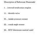
- Fig. 1 is a schematic diagram showing the configuration of an internal combustion engine and its peripheral equipment to which an atmospheric pressure detector according to an embodiment of the present invention is applied.
- reference numeral 1 denotes a single-cylinder water-cooled internal combustion engine (an engine), and air from an air cleaner 3 is introduced into an intake air passage 2 of the internal combustion engine 1.
- a throttle valve 11 adapted to be opened and closed in conjunction with the operation of an accelerator pedal or the like, which is not shown.
- the amount of intake air (the amount of air to be taken in) to the intake air passage 2 is regulated by opening or closing the throttle valve 11.
- fuel is injected and supplied into the internal combustion engine 1 from an injector (a fuel injection valve) 5 provided in the intake air passage 2 at a position near an intake port 4 together with intake air so introduced into the intake air passage 2.
- air-fuel mixture comprising a predetermined amount of fuel and a predetermined amount of intake air is drawn into a combustion chamber 7 via an intake valve 6.
- an intake pressure sensor 21 for detecting the intake pressure PM [mmHg] within the intake air passage 2 is provided on a downstream side of the throttle valve 11 and in the intake air passage.
- a crank angle sensor 22 for detecting the crank angle [°CA (Crank Angle)] of a crankshaft 12 of the internal combustion engine 1 is provided at the crankshaft 12.
- the engine speed NE of the internal combustion engine 1 is calculated according to crank angles detected by the crank angle sensor 22.
- a spark plug 13 is disposed in such a manner as to be directed toward the interior of the combustion chamber 7 in the internal combustion engine 1.
- a high voltage from an ignition coil/igniter 14 is applied to the spark plug 13 in synchronism with a crank angle detected by the crank angle sensor 22 based on an ignition command signal outputted from an ECU (Electronic Control Unit) 30, which will be described later, whereby an air-fuel mixture within the combustion chamber 7 is ignited for combustion.
- ECU Electronic Control Unit
- the ECU 30 is configured as a logic arithmetic circuit comprising a CPU as a central processing unit for executing known various types of arithmetic processing, a ROM 32 for storing control programs, a RAM 33 for storing various types of data, a B/U (back-up line) RAM 34, an input/output circuit 35 and a bus line 36 for connecting those constituent components.
- Intake pressures PM from the intake pressure sensor 21, crank angles from the crank angle sensor 22 and so on are inputted into the ECU 30.
- the injector 5 which is associated with fuel injection timings and fuel injection amounts, and the spark plug 13 and the ignition coil/igniter 14 which are associated with ignition timings, and so on are appropriately controlled based on output signals sent out from the ECU 30 based on various types of sensor information.
- This N signal is a signal for representing each of crank angle positions "0" to “23” given every 30 [°CA] relative to a crank angle of 720 [°CA] comprising 4 cycles (induction stroke ⁇ compression stroke ⁇ expansion (combustion) stroke ⁇ exhaust stroke) with a reference crank angle position detected by the crank angle sensor 22 of the crankshaft 12 of the internal combustion engine 1 being "0". Note that this atmospheric arithmetic subroutine is repeatedly executed by the CPU 31 every time a predetermined time elapses.
- step S103 If a determination condition for step S103 is met or it is determined that the number of samplings of intake pressures PMi is equal to or greater than the predetermined number A, then the procedure moves to step S104, where the maximum of the plurality of intake pressures PMi so read is determined as the intake pressure maximum PMMAX. Next, the flow advances to step S105, where the minimum of the plurality of intake pressures PMi so read is determined as the intake pressure minimum PMMIN.
- step S106 the flow moves to step S106, and whether or not a difference, resulting when the intake pressure minimum PMMIN obtained in step S105 is subtracted from the intake pressure maximum PMMAX obtained in step S105, falls within a predetermined value ⁇ is determined.
- a determination condition for step S106 is met or it is determined that the difference ⁇ PM (refer to Fig. 3) between the intake pressure maximum PMMAX and the intake pressure minimum PMMIN falls within the predetermined value ⁇
- step S107 the total of the intake pressures read in step S102 is divided by the predetermined number A to obtain an intake pressure average PMAV.
- step S108 the intake pressure average PMAV obtained in step S107 is determined as an atmospheric pressure PA and the routine ends.
- step S101 determines whether there is no N signal, or if the determination condition for step S103 is not met and it is determined that the number of samplings of intake pressures PMi is small enough to be less than the predetermined number A, no accurate atmospheric pressure can be calculated, or, if the determination condition for step S106 is not met and the difference ⁇ PM between the intake pressure maximum PMMAX and the intake pressure minimum PMMIN is large enough to exceed the predetermined value ⁇ , the intake pressure in the internal combustion engine 1 varies largely, and therefore, it is determined that the condition is not suitable for calculation of atmospheric pressure PA, and the routine ends without doing anything.
- the atmospheric pressure detector for an internal combustion engine comprises the intake pressure sensor 21 functioning as the intake pressure detecting means for detecting intake pressures PMi [mmHg] which are pressures of intake air introduced to the downstream side of the throttle valve 11 disposed in the intake air passage 2 of the internal combustion engine 1, the crank angle sensor 22 functioning as the crank angle detecting means for detecting crank angle positions every time the internal combustion engine 1 turns through 30° [°CA] and the atmospheric pressure calculating means which is attained by the CPU 31 within the ECU 30 for smoothing intake pressures PMi detected by the intake pressure sensor 21 relative to crank angle positions detected every time the internal combustion engine 1 turns through 30° [°CA] according to their transition conditions for calculation as an atmospheric pressure PA.
- the intake pressure sensor 21 functioning as the intake pressure detecting means for detecting intake pressures PMi [mmHg] which are pressures of intake air introduced to the downstream side of the throttle valve 11 disposed in the intake air passage 2 of the internal combustion engine 1
- the crank angle sensor 22 functioning as the crank angle detecting means for detecting crank angle positions every time the internal
- the atmospheric pressure calculating means of the atmospheric pressure detector for an internal combustion engine is designed to smooth intake pressures PMi in case the difference ⁇ PM between the maximum PMMAX and the minimum PMMIN of the plurality of intake pressures PMi [mmhg] detected by the intake pressure sensor 21 every 30° [°CA] which is the predetermined crank angle position detected by the crank angle sensor 22 falls within the predetermined value ⁇ .
- intake pressures PMi are detected at each predetermined crank angle position of every 30° [°CA] after the internal combustion engine 1 is started, and the intake pressures PMi so detected are smoothed according to the transition conditions and the result is obtained as the atmospheric pressure PA.
- the difference ⁇ PM between the maximum PMMAX and the minimum PMMIN of the plurality of intake pressures PMi is small enough to fall within the predetermined value ⁇ , the plurality of intake pressures PMi are smoothed.
- the atmospheric pressure PA when the intake pressures PMi are stable, can be obtained by the plurality of samplings at the crank angle positions, the reliability can be increased.
- step S206 corresponds to the steps S101 to 106 described above with respect to the embodiment, the detailed description of those steps will be omitted.
- step S207 where, of the intake pressures PMi read in step S202, the total of the intake pressures read every 30° [°CA] from 360° [°CA] to 720° [°CA] are divided by the number (B) of intake pressures, and the result is determined as an intake pressure average PMAV.
- step S208 where the intake pressure average PMAV obtained in step S207 is determined as an atmospheric pressure PA, and the routine ends.
- step S201 determines whether there is no N signal, or if the determination condition for step S203 is not met and it is determined that the number of samplings of intake pressures PMi is small enough to be less than the predetermined number A, no accurate atmospheric pressure PA can be calculated, or, if the determination condition for step S206 is not met and the difference ⁇ PM between the intake pressure maximum PMMAX and the intake pressure minimum PMMIN is large enough to exceed the predetermined value ⁇ , the intake pressure in the internal combustion engine 1 varies largely and, therefore, it is determined that the condition is not suitable for calculation of atmospheric pressure PA, and the routine ends without doing anything.
- the atmospheric pressure calculating means of the atmospheric pressure detector for an internal combustion engine according to the first modification which is attained by the CPU 31 in the ECU 30 is designed to smooth intake pressures PMi in case the difference ⁇ PM between the maximum PMMAX and the minimum PMMIN of the plurality of intake pressures PMi [mmHg], detected by the intake pressure sensor 21 at predetermined crank angle positions from the expansion stroke to the exhaust stroke of the internal combustion engine 1 which are detected by the crank angle sensor 22 of every 30° [°CA] from 360° [°CA] to 720° [°CA], falls within the predetermined value ⁇ .
- steps S301 to S306 correspond to the steps S101 to 106 described above with respect to the embodiment, a detailed description of those steps will be omitted.
- the flow advances to step S307, where of intake pressures PMi read in step S302, the total of the intake pressures at predetermined crank angles such as X° [°CA], Y° [°CA], Z° [°CA] are divided by the number C of predetermined crank angles, and the result is determined as an intake pressure average PMAV.
- step S308 where the intake pressure average PMAV obtained in step S307 is determined as an atmospheric pressure PA, and the routine ends.
- step S301 determines whether there is no N signal, or if the determination condition for step S303 is not met and it is determined that the number of samplings of intake pressures PMi is small enough to be less than the predetermined number A, no accurate atmospheric pressure PA can be calculated, or, in case the determination condition for step S306 is not met and the difference ⁇ PM between the intake pressure maximum PMMAX and the intake pressure minimum PMMIN is large enough to exceed the predetermined value ⁇ , the intake pressure in the internal combustion engine 1 varies largely and, therefore, it is determined that the condition is not suitable for calculation of atmospheric pressure PA, and the routine ends without doing anything.
- the atmospheric pressure calculating means of the atmospheric pressure detector for an internal combustion engine according to the second modification which is attained by the CPU 31 in the ECU 30 is designed to smooth intake pressures PMi in case the difference ⁇ PM between the maximum PMMAX and the minimum PMMIN of the plurality of intake pressures PMi [mmHg] detected by the intake pressure sensor 21 relative to the plurality of optional crank angle positions X°, Y°, Z° [°CA] from the expansion stroke to the exhaust stroke of the internal combustion engine 1 which are detected by the crank angle sensor 22, falls within the predetermined value ⁇ .
- step S406 corresponds to the steps S101 to 106 described above with respect to the embodiment, a detailed description of those steps will be omitted.
- step S406 the total of intake pressures PMi read in step S402 is divided by a predetermined number A and the result is determined as an intake pressure average PMAV.
- step S407 the flow moves to step S407, and whether or not a difference, resulting when the intake pressure average PMAV obtained in step S406 is subtracted from the intake pressure maximum PMMAX obtained in step S404, falls within a predetermined value ⁇ is determined. If a determination condition for step S407 is met and it is determined that the difference between the intake pressure maximum PMMAX and the intake pressure average PMAV falls within the predetermined value ⁇ , then the flow advances to step S408, where whether or not a difference, resulting when the intake pressure minimum PMMIN obtained in step S405 is subtracted from the intake pressure average PMAV obtained in step S406, falls within a predetermined value ⁇ is determined.
- step S408 If a determination condition for step S408 is met and it is determined that the difference between the intake pressure average PMAV and the intake pressure minimum PMMIN falls within the predetermined value ⁇ , the flow then advances to step S409, where the intake pressure average PMAV obtained in step S406 is determined as an atmospheric pressure PA, and the routine ends.
- step S401 determines whether there is no N signal, or if the determination condition for step S403 is not met and it is determined that the number of samplings of intake pressures PMi is small enough to be less than the predetermined number A, no accurate atmospheric pressure PA can be calculated, or, if the determination condition for step S407 is not met and it is determined that the difference between the intake pressure maximum PMMAX and the intake pressure average PMAV is large enough to exceed the predetermined value ⁇ , as a change in intake pressure in the internal combustion engine 1 is large, it is determined that the condition is not suitable for calculation of an atmospheric pressure PA, or if a determination condition for step S408 is not met and it is determined that the difference between the intake pressure average PMAV and the intake pressure minimum PMMIN is large enough to exceed the predetermined value ⁇ , as a change in intake pressures in the internal combustion engine 1 is large, it is determined that the condition is not suitable for calculation of an atmospheric pressure PA, and the routine ends without doing anything.
- the atmospheric pressure detector for an internal combustion engine comprises the intake pressure sensor 21 functioning as the intake pressure detecting means for detecting intake pressures PMi [mmHg] which are pressures of intake air introduced into the downstream side of the throttle valve 11 disposed in the intake air passage 2 of the internal combustion engine 1, the intake pressure smoothing means attained by the CPU 31 in the ECU 30 for smoothing intake pressures PMi in case the variation in the intake pressures PMi detected by the intake sensor 21 attained by the CPU 31 in the ECU 30 falls within the predetermined value, and the atmospheric pressure calculating means attained by the CPU 31 in the ECU 30 for calculating the smoothed intake pressure average PMAV as an atmospheric pressure PA.
- natural intake pressures PMi can be obtained in a stable fashion by the samplings resulting when the variation in the intake pressures PMi detected by the intake pressure sensor 21 falls within the predetermined value, and the accurate atmospheric pressure PA can be obtained using the intake pressure average PMAV obtained from the smoothed intake pressures PMi, and therefore, the reliability of the atmospheric pressure detector so modified can be increased.
- the intake pressure smoothing means attained by the CPU 31 in the ECU 30 of the atmospheric pressure detector for an internal combustion engine according to the third modification is designed to smooth intake pressures PMi in case the differences between the intake pressure average PMAV which is the average of the intake pressures PMi detected by the intake pressure sensor 21 and the intake pressure maximum PMMAX which is the peak of the intake pressures PMi detected by the intake pressure sensor 21 and the intake pressure minimum PMMIN wall fall within ⁇ , ⁇ , respectively.
- the intake pressure average PMAV which is based upon the intake pressures PMi detected by the intake pressure sensor 21, and the intake pressure maximum PMMAX and the intake pressure minimum PMMIN are small enough to fall within ⁇ , ⁇ , respectively, the intake pressures PMi sampled are stable, and the accurate atmospheric pressure PA can be obtained using the intake pressure average PMAV resulting when the intake pressures PMi so sampled are smoothed, and therefore, the reliability of the atmospheric pressure detector so modified can be increased.
- step S505 the minimum of the plurality of intake pressures PMi so read is determined as the intake pressure minimum PMMIN.
- step S506 the total of the intake pressures PMi read in step S502 is divided by a predetermined number D, and the result is determined as an intake pressure average PMAV.
- step S507 the flow advances to step S507, and whether or not a difference resulting when the intake pressure average PMAV obtained in step S506 is subtracted from the intake pressure maximum PMMAX obtained in step S504 falls within a predetermined value ⁇ is determined. If a determination condition for step S507 is met and it is determined that the difference between the intake pressure maximum PMMAX and the intake pressure average PMAV falls within the predetermined value ⁇ , then the flow advances to step S508, and whether or not a difference resulting when the intake pressure minimum PMMIN obtained in step S505 is subtracted from the intake pressure average PMAV obtained in step S506 falls within a predetermined value ⁇ is determined.
- step S508 If a determination condition for step S508 is met and it is determined that the difference between the intake pressure average PMAV and the intake pressure minimum PMMIN falls within ⁇ , then the flow advances to step S509, where the intake pressure average PMAV obtained in step S506 is determined as an atmospheric pressure PA, and the routine ends.
- step S501 determines whether a determination condition for step S501 is met and it is determined that the exhaust stroke has not yet been reached, or if a determination condition for step S503 is not met and it is determined that the exhaust stroke has ended, as an accurate atmospheric pressure PA cannot be calculated, or if a determination condition for step S507 is not met and the difference between the intake pressure maximum PMMAX and the intake pressure average PMAV is large enough to exceed the predetermined value ⁇ , as the variation in intake pressures in the internal combustion engine 1 is large, it is determined that the condition of the internal combustion engine is not suitable for calculation of an atmospheric pressure PA, or if a determination condition for step S508 is not met and the difference between the intake pressure average PMAV and the intake pressure minimum PMMIN is large enough to exceed the predetermined value ⁇ , as the variation in intake pressures in the internal combustion engine 1 is large, it is determined that the condition of the internal combustion engine 1 is not suitable for calculation of an atmospheric pressure PA, and the routine ends.
- the atmospheric pressure detector for an internal combustion engine comprises the intake pressure sensor 21 functioning as the intake pressure detecting means for detecting intake pressures PMi [mmHg] which are pressures of intake air introduced into the downstream side of the throttle valve 11 disposed in the intake air passage 2 of the internal combustion engine 1, the exhaust stroke detecting means attained by the CPU 31 in the ECU 30 for detecting an exhaust stroke of the internal combustion engine 1, the intake pressure smoothing means attained by the CPU 31 in the ECU 30 for smoothing intake pressures PMi detected by the intake pressure detecting means 21 during the predetermined period of time from the start of the exhaust stroke to the end of the exhaust stroke which were detected by the exhaust stroke detecting means and the atmospheric pressure calculating means attained by the CPU 31 in the ECU 30 for calculating the intake pressure average PMAV smoothed by the intake pressure smoothing means as an atmospheric pressure PA.
- the variation in intake pressures PMi is relatively small within the predetermined period of time from the start of the exhaust stroke to the end of the exhaust stroke.
- an accurate atmospheric pressure PA can be obtained by using the intake pressure average PMAV which is the smoothed intake pressures PMi, the reliability of the atmospheric pressure detector according to the fourth modification can be increased.
- a predetermined period of time including the exhaust stroke can be specified from the understanding that the exhaust stroke is started after a predetermined period of time has elapsed from the generation of the minimum intake pressure in the intake pressure variation using the engine speed NE of the internal combustion engine 1 as a parameter.
- a predetermined period of time including the exhaust stroke can be specified from the understanding that the exhaust stroke is started after a predetermined period of time has elapsed from the generation of a predetermined cam signal using the engine speed NE of the internal combustion engine 1 as a parameter.
- intake pressures PMi are sampled by means of the intake pressure sensor 21 when an N signal interruption occurs every 30° [°CA] which is detected by the crank angle sensor 22, the present invention is not limited thereto in carrying out the same, but intake pressures PMi may be designed to be sampled at other crank angle positions. In addition, the plurality of intake pressures PMi which are finally smoothed may be sampled at different crank angle positions.
- a preferred amount of fuel can be injected for supply into the internal combustion engine by reflecting the variation in atmospheric pressure PA obtained by the embodiment and the modifications thereto to the intake pressure PM.
Landscapes
- Engineering & Computer Science (AREA)
- Chemical & Material Sciences (AREA)
- Combustion & Propulsion (AREA)
- Mechanical Engineering (AREA)
- General Engineering & Computer Science (AREA)
- Combined Controls Of Internal Combustion Engines (AREA)
- Measuring Fluid Pressure (AREA)
Abstract
Description
Claims (7)
- An atmospheric pressure detector for an internal combustion engine comprising;
Intake pressure detecting means for detecting intake pressures which are pressures of intake air introduced to a downstream side of a throttle valve disposed in an intake air passage of said internal combustion engine,
crank angle detecting means for detecting predetermined crank angle positions of said internal combustion engine, and
atmospheric pressure calculating means for smoothing intake pressures detected by said intake pressure detecting means relative to said predetermined crank angle positions detected by said crank angle detecting means according to transition conditions thereof and calculating said intake pressures so smoothed as an atmospheric pressure. - An atmospheric pressure detector for an internal combustion engine as set forth in Claim 1, wherein said atmospheric pressure calculating means smoothes said plurality of intake pressures detected relative to said respective predetermined crank angle positions provided that a difference between the maximum value and the minimum of said intake pressures so detected falls within a predetermined value.
- An atmospheric pressure detector for an internal combustion engine as set forth in Claim 1, wherein said atmospheric pressure calculating means smoothes said plurality of intake pressures detected relative to said respective predetermined crank angle positions from an expansion stroke to an exhaust stroke of said internal combustion engine provided that a difference between the maximum and the minimum of said intake pressures so detected falls within a predetermined value.
- An atmospheric pressure detector for an internal combustion engine as set forth in Claim 1, wherein said atmospheric pressure calculating means smoothes said plurality of intake pressures detected relative to said respective predetermined crank angle positions from an induction stroke to an exhaust stroke of said internal combustion engine provided that a difference between the maximum and the minimum of said intake pressures so detected falls within a predetermined value.
- An atmospheric pressure detector for an internal combustion engine comprising;
Intake pressure detecting means for detecting intake pressures which are pressures of intake air introduced to a downstream side of a throttle valve disposed in an intake air passage of said internal combustion engine,
intake pressure smoothing means for smoothing intake pressures detected by said intake pressure detecting means provided that a variation in said intake pressures so detected falls within a predetermined value, and
atmospheric pressure calculating means for calculating said intake pressures smoothed by said intake pressure smoothing means as an atmospheric pressure. - An atmospheric pressure detector for an internal combustion engine as set forth in Claim 5, wherein said intake pressure smoothing means smoothes intake pressures detected by said intake pressure detecting means provided that a difference between the average of said intake pressures and the peak of said intake pressures falls within a predetermined value.
- An atmospheric pressure detector for an internal combustion engine comprising;
Intake pressure detecting means for detecting intake pressures which are pressures of intake air introduced to a downstream side of a throttle valve disposed in an intake air passage of said internal combustion engine,
exhaust stroke detecting means for detecting an exhaust stroke of said internal combustion engine,
intake pressure smoothing means for smoothing intake pressures detected by said intake pressure detecting means within a predetermined period of time including at least an exhaust stroke detected by said exhaust stroke detecting means, and
atmospheric pressure calculating means for calculating said intake pressures smoothed by said intake pressure smoothing means as an atmospheric pressure.
Applications Claiming Priority (5)
| Application Number | Priority Date | Filing Date | Title |
|---|---|---|---|
| JP2001308628 | 2001-10-04 | ||
| JP2001308628 | 2001-10-04 | ||
| JP2002270007A JP2003176749A (en) | 2001-10-04 | 2002-09-17 | Atmospheric pressure detection device for internal combustion engine |
| JP2002270007 | 2002-09-17 | ||
| PCT/JP2002/010340 WO2003031793A1 (en) | 2001-10-04 | 2002-10-03 | Atmospheric pressure detector of internal combustion engine |
Publications (3)
| Publication Number | Publication Date |
|---|---|
| EP1433944A1 true EP1433944A1 (en) | 2004-06-30 |
| EP1433944A4 EP1433944A4 (en) | 2008-10-29 |
| EP1433944B1 EP1433944B1 (en) | 2012-08-08 |
Family
ID=26623700
Family Applications (1)
| Application Number | Title | Priority Date | Filing Date |
|---|---|---|---|
| EP02779903A Expired - Lifetime EP1433944B1 (en) | 2001-10-04 | 2002-10-03 | Atmospheric pressure detector of internal combustion engine |
Country Status (4)
| Country | Link |
|---|---|
| EP (1) | EP1433944B1 (en) |
| JP (1) | JP2003176749A (en) |
| CN (1) | CN100510363C (en) |
| WO (1) | WO2003031793A1 (en) |
Cited By (7)
| Publication number | Priority date | Publication date | Assignee | Title |
|---|---|---|---|---|
| EP2011983A1 (en) * | 2007-07-05 | 2009-01-07 | MAGNETI MARELLI POWERTRAIN S.p.A. | Method for the acquisition and processing of an intake pressure signal in an internal combustion engine without an intake manifold |
| US20130245916A1 (en) * | 2012-03-15 | 2013-09-19 | Hitachi Automotive Systems, Ltd. | Engine Control Unit and Atmospheric Pressure Estimation Method |
| EP2644881A3 (en) * | 2012-03-26 | 2014-12-10 | Suzuki Motor Corporation | Engine start control system |
| FR3089257A1 (en) * | 2018-12-04 | 2020-06-05 | Continental Automotive France | Method of controlling an internal combustion engine learning atmospheric pressure |
| EP3825539A4 (en) * | 2018-09-21 | 2021-09-08 | Honda Motor Co., Ltd. | ENGINE RESTART DEVICE |
| FR3128490A1 (en) * | 2021-10-27 | 2023-04-28 | Vitesco Technologies | Method for estimating atmospheric pressure for an internal combustion engine |
| EP4603694A1 (en) * | 2024-02-13 | 2025-08-20 | Nikki Co., Ltd. | Method of diagnosing responsiveness of pressure sensor of intake manifold |
Families Citing this family (3)
| Publication number | Priority date | Publication date | Assignee | Title |
|---|---|---|---|---|
| JP4548269B2 (en) * | 2005-08-10 | 2010-09-22 | 国産電機株式会社 | Method and apparatus for detecting atmospheric pressure for internal combustion engine control |
| JP2008019742A (en) * | 2006-07-11 | 2008-01-31 | Yamaha Motor Co Ltd | Atmospheric pressure estimation device, vehicle, and atmospheric pressure estimation program |
| JP2020186676A (en) * | 2019-05-14 | 2020-11-19 | 愛三工業株式会社 | Control device |
Family Cites Families (5)
| Publication number | Priority date | Publication date | Assignee | Title |
|---|---|---|---|---|
| JPS59188530A (en) * | 1983-04-08 | 1984-10-25 | Isuzu Motors Ltd | Apparatus for measuring atmospheric pressure for internal combustion engine |
| JPS61185646A (en) | 1985-02-12 | 1986-08-19 | Nippon Denso Co Ltd | Control device for internal-combustion engine |
| JPH01280662A (en) * | 1988-05-06 | 1989-11-10 | Mitsubishi Electric Corp | Atmospheric pressure detecting device for control of engine |
| JP2682762B2 (en) | 1991-06-24 | 1997-11-26 | 三菱電機株式会社 | Internal combustion engine control device |
| JP3449813B2 (en) * | 1995-01-06 | 2003-09-22 | 株式会社日立ユニシアオートモティブ | Atmospheric pressure estimation device for internal combustion engine |
-
2002
- 2002-09-17 JP JP2002270007A patent/JP2003176749A/en active Pending
- 2002-10-03 WO PCT/JP2002/010340 patent/WO2003031793A1/en not_active Ceased
- 2002-10-03 EP EP02779903A patent/EP1433944B1/en not_active Expired - Lifetime
- 2002-10-03 CN CNB028031245A patent/CN100510363C/en not_active Expired - Lifetime
Cited By (15)
| Publication number | Priority date | Publication date | Assignee | Title |
|---|---|---|---|---|
| EP2011983A1 (en) * | 2007-07-05 | 2009-01-07 | MAGNETI MARELLI POWERTRAIN S.p.A. | Method for the acquisition and processing of an intake pressure signal in an internal combustion engine without an intake manifold |
| US7801691B2 (en) | 2007-07-05 | 2010-09-21 | Magneti Marelli Powertrain S.P.A. | Method for acquisition and processing of an intake pressure signal in an internal combustion engine without an intake manifold |
| CN103256131B (en) * | 2007-07-05 | 2016-05-11 | 马涅蒂-马瑞利动力系统公司 | There is no the acquisition and processing method of the admission pressure signal in the internal combustion engine of inlet manifold |
| US20130245916A1 (en) * | 2012-03-15 | 2013-09-19 | Hitachi Automotive Systems, Ltd. | Engine Control Unit and Atmospheric Pressure Estimation Method |
| EP2644881A3 (en) * | 2012-03-26 | 2014-12-10 | Suzuki Motor Corporation | Engine start control system |
| US9347417B2 (en) | 2012-03-26 | 2016-05-24 | Suzuki Motor Corporation | Engine start control system |
| EP3825539A4 (en) * | 2018-09-21 | 2021-09-08 | Honda Motor Co., Ltd. | ENGINE RESTART DEVICE |
| FR3089256A1 (en) * | 2018-12-04 | 2020-06-05 | Continental Automotive France | Method of controlling an internal combustion engine learning atmospheric pressure |
| WO2020115098A1 (en) * | 2018-12-04 | 2020-06-11 | Continental Automotive France | Method for controlling an internal combustion engine with learning of atmospheric pressure |
| FR3089257A1 (en) * | 2018-12-04 | 2020-06-05 | Continental Automotive France | Method of controlling an internal combustion engine learning atmospheric pressure |
| US11415072B2 (en) | 2018-12-04 | 2022-08-16 | Vitesco Technologies GmbH | Method for controlling an internal combustion engine with learning of atmospheric pressure |
| FR3128490A1 (en) * | 2021-10-27 | 2023-04-28 | Vitesco Technologies | Method for estimating atmospheric pressure for an internal combustion engine |
| WO2023072565A1 (en) * | 2021-10-27 | 2023-05-04 | Vitesco Technologies GmbH | Method for estimating the atmospheric pressure of an internal combustion engine |
| US12442343B2 (en) | 2021-10-27 | 2025-10-14 | Vitesco Technologies GmbH | Method for estimating the atmospheric pressure of an internal combustion engine |
| EP4603694A1 (en) * | 2024-02-13 | 2025-08-20 | Nikki Co., Ltd. | Method of diagnosing responsiveness of pressure sensor of intake manifold |
Also Published As
| Publication number | Publication date |
|---|---|
| CN100510363C (en) | 2009-07-08 |
| WO2003031793A1 (en) | 2003-04-17 |
| EP1433944B1 (en) | 2012-08-08 |
| CN1476515A (en) | 2004-02-18 |
| JP2003176749A (en) | 2003-06-27 |
| EP1433944A4 (en) | 2008-10-29 |
Similar Documents
| Publication | Publication Date | Title |
|---|---|---|
| EP0130382B1 (en) | Method of fuel injection into engine | |
| EP1229230A3 (en) | Control apparatus for multi-cylinder internal combustion engine and control method | |
| EP1437498B1 (en) | 4−STROKE ENGINE CONTROL DEVICE AND CONTROL METHOD | |
| EP1433944B1 (en) | Atmospheric pressure detector of internal combustion engine | |
| EP1788229A1 (en) | Combustion state determination method for internal combustion engine | |
| JPS638296B2 (en) | ||
| US6390065B2 (en) | Method of reduction of cold-start emissions from internal combustion engines | |
| JP2000002157A (en) | Electronic engine control device | |
| EP0909887A2 (en) | Idle speed control system for spark ignited engines | |
| EP1431551B1 (en) | Controller for internal combustion engine | |
| JP2002147269A (en) | Engine control device | |
| JP2004257386A (en) | Engine air amount prediction method based on engine position, control program for internal combustion engine, and control system for internal combustion engine | |
| JP3654781B2 (en) | Measuring device for intake air amount of internal combustion engine | |
| US6915790B2 (en) | Piston engine and associated operating process | |
| EP0161611B1 (en) | Method and apparatus for controlling air-fuel ratio in internal combustion engine | |
| JP4337247B2 (en) | Control device for internal combustion engine | |
| US7380444B2 (en) | Acceleration/deceleration detection device and method for four-cycle engines | |
| CN100507243C (en) | Device for determining the operating state of an internal combustion engine | |
| JP3963099B2 (en) | Operating state discrimination device for internal combustion engine | |
| US6705288B2 (en) | Starting control apparatus for internal combustion engine | |
| US5503126A (en) | Ignition timing control system for internal combustion engines | |
| JP2006009632A (en) | Control device for internal combustion engine | |
| JP4046718B2 (en) | Engine fuel injection control method | |
| JP4304669B2 (en) | Crank angle discrimination device for internal combustion engine | |
| JP4239087B2 (en) | Engine acceleration / deceleration determination method and apparatus |
Legal Events
| Date | Code | Title | Description |
|---|---|---|---|
| PUAI | Public reference made under article 153(3) epc to a published international application that has entered the european phase |
Free format text: ORIGINAL CODE: 0009012 |
|
| 17P | Request for examination filed |
Effective date: 20030603 |
|
| AK | Designated contracting states |
Kind code of ref document: A1 Designated state(s): AT BE CH CY DE DK ES FI FR GB GR IE IT LI LU MC NL PT SE TR |
|
| REG | Reference to a national code |
Ref country code: DE Ref legal event code: 8566 |
|
| A4 | Supplementary search report drawn up and despatched |
Effective date: 20080930 |
|
| 17Q | First examination report despatched |
Effective date: 20091228 |
|
| GRAP | Despatch of communication of intention to grant a patent |
Free format text: ORIGINAL CODE: EPIDOSNIGR1 |
|
| RIC1 | Information provided on ipc code assigned before grant |
Ipc: F02D 41/18 20060101ALI20110824BHEP Ipc: F02D 45/00 20060101AFI20110824BHEP |
|
| RBV | Designated contracting states (corrected) |
Designated state(s): IT |
|
| GRAS | Grant fee paid |
Free format text: ORIGINAL CODE: EPIDOSNIGR3 |
|
| GRAA | (expected) grant |
Free format text: ORIGINAL CODE: 0009210 |
|
| AK | Designated contracting states |
Kind code of ref document: B1 Designated state(s): IT |
|
| PLBE | No opposition filed within time limit |
Free format text: ORIGINAL CODE: 0009261 |
|
| STAA | Information on the status of an ep patent application or granted ep patent |
Free format text: STATUS: NO OPPOSITION FILED WITHIN TIME LIMIT |
|
| 26N | No opposition filed |
Effective date: 20130510 |
|
| PGFP | Annual fee paid to national office [announced via postgrant information from national office to epo] |
Ref country code: IT Payment date: 20201026 Year of fee payment: 19 |
|
| PG25 | Lapsed in a contracting state [announced via postgrant information from national office to epo] |
Ref country code: IT Free format text: LAPSE BECAUSE OF NON-PAYMENT OF DUE FEES Effective date: 20211003 |