EP1433928A2 - Brush seal for a turbomachine - Google Patents
Brush seal for a turbomachine Download PDFInfo
- Publication number
- EP1433928A2 EP1433928A2 EP03257867A EP03257867A EP1433928A2 EP 1433928 A2 EP1433928 A2 EP 1433928A2 EP 03257867 A EP03257867 A EP 03257867A EP 03257867 A EP03257867 A EP 03257867A EP 1433928 A2 EP1433928 A2 EP 1433928A2
- Authority
- EP
- European Patent Office
- Prior art keywords
- seal
- axis
- rubplate
- brushpack
- rotor
- Prior art date
- Legal status (The legal status is an assumption and is not a legal conclusion. Google has not performed a legal analysis and makes no representation as to the accuracy of the status listed.)
- Withdrawn
Links
- 238000007789 sealing Methods 0.000 claims abstract description 11
- 239000000463 material Substances 0.000 claims description 8
- 229910000601 superalloy Inorganic materials 0.000 claims description 3
- 239000010941 cobalt Substances 0.000 claims description 2
- 229910017052 cobalt Inorganic materials 0.000 claims description 2
- GUTLYIVDDKVIGB-UHFFFAOYSA-N cobalt atom Chemical compound [Co] GUTLYIVDDKVIGB-UHFFFAOYSA-N 0.000 claims description 2
- 238000000034 method Methods 0.000 claims 2
- 229910000831 Steel Inorganic materials 0.000 claims 1
- 229910001220 stainless steel Inorganic materials 0.000 claims 1
- 239000010935 stainless steel Substances 0.000 claims 1
- 239000010959 steel Substances 0.000 claims 1
- PXHVJJICTQNCMI-UHFFFAOYSA-N Nickel Chemical compound [Ni] PXHVJJICTQNCMI-UHFFFAOYSA-N 0.000 description 4
- IJGRMHOSHXDMSA-UHFFFAOYSA-N Atomic nitrogen Chemical compound N#N IJGRMHOSHXDMSA-UHFFFAOYSA-N 0.000 description 2
- XEEYBQQBJWHFJM-UHFFFAOYSA-N Iron Chemical compound [Fe] XEEYBQQBJWHFJM-UHFFFAOYSA-N 0.000 description 2
- 230000003993 interaction Effects 0.000 description 2
- 229910052759 nickel Inorganic materials 0.000 description 2
- OKTJSMMVPCPJKN-UHFFFAOYSA-N Carbon Chemical compound [C] OKTJSMMVPCPJKN-UHFFFAOYSA-N 0.000 description 1
- VYZAMTAEIAYCRO-UHFFFAOYSA-N Chromium Chemical compound [Cr] VYZAMTAEIAYCRO-UHFFFAOYSA-N 0.000 description 1
- PWHULOQIROXLJO-UHFFFAOYSA-N Manganese Chemical compound [Mn] PWHULOQIROXLJO-UHFFFAOYSA-N 0.000 description 1
- 229910001257 Nb alloy Inorganic materials 0.000 description 1
- 229910000990 Ni alloy Inorganic materials 0.000 description 1
- 241000904500 Oxyspora paniculata Species 0.000 description 1
- OAICVXFJPJFONN-UHFFFAOYSA-N Phosphorus Chemical compound [P] OAICVXFJPJFONN-UHFFFAOYSA-N 0.000 description 1
- XUIMIQQOPSSXEZ-UHFFFAOYSA-N Silicon Chemical compound [Si] XUIMIQQOPSSXEZ-UHFFFAOYSA-N 0.000 description 1
- NINIDFKCEFEMDL-UHFFFAOYSA-N Sulfur Chemical compound [S] NINIDFKCEFEMDL-UHFFFAOYSA-N 0.000 description 1
- 239000005864 Sulphur Substances 0.000 description 1
- KMCVQCJLAZSHCL-UHFFFAOYSA-N [Nb].[Mo].[Cr].[Ni] Chemical compound [Nb].[Mo].[Cr].[Ni] KMCVQCJLAZSHCL-UHFFFAOYSA-N 0.000 description 1
- 229910000963 austenitic stainless steel Inorganic materials 0.000 description 1
- 229910052799 carbon Inorganic materials 0.000 description 1
- 229910052804 chromium Inorganic materials 0.000 description 1
- 239000011651 chromium Substances 0.000 description 1
- 238000010276 construction Methods 0.000 description 1
- 230000007797 corrosion Effects 0.000 description 1
- 238000005260 corrosion Methods 0.000 description 1
- 230000003247 decreasing effect Effects 0.000 description 1
- 230000002452 interceptive effect Effects 0.000 description 1
- 229910052742 iron Inorganic materials 0.000 description 1
- 230000000670 limiting effect Effects 0.000 description 1
- 229910052748 manganese Inorganic materials 0.000 description 1
- 239000011572 manganese Substances 0.000 description 1
- 229910001092 metal group alloy Inorganic materials 0.000 description 1
- 238000012986 modification Methods 0.000 description 1
- 230000004048 modification Effects 0.000 description 1
- 229910052757 nitrogen Inorganic materials 0.000 description 1
- 230000003534 oscillatory effect Effects 0.000 description 1
- 230000036961 partial effect Effects 0.000 description 1
- 230000002093 peripheral effect Effects 0.000 description 1
- 229910052698 phosphorus Inorganic materials 0.000 description 1
- 239000011574 phosphorus Substances 0.000 description 1
- 230000002829 reductive effect Effects 0.000 description 1
- 229910052710 silicon Inorganic materials 0.000 description 1
- 239000010703 silicon Substances 0.000 description 1
- 238000003466 welding Methods 0.000 description 1
Images

Classifications
-
- F—MECHANICAL ENGINEERING; LIGHTING; HEATING; WEAPONS; BLASTING
- F16—ENGINEERING ELEMENTS AND UNITS; GENERAL MEASURES FOR PRODUCING AND MAINTAINING EFFECTIVE FUNCTIONING OF MACHINES OR INSTALLATIONS; THERMAL INSULATION IN GENERAL
- F16J—PISTONS; CYLINDERS; SEALINGS
- F16J15/00—Sealings
- F16J15/16—Sealings between relatively-moving surfaces
- F16J15/32—Sealings between relatively-moving surfaces with elastic sealings, e.g. O-rings
- F16J15/3284—Sealings between relatively-moving surfaces with elastic sealings, e.g. O-rings characterised by their structure; Selection of materials
- F16J15/3288—Filamentary structures, e.g. brush seals
-
- F—MECHANICAL ENGINEERING; LIGHTING; HEATING; WEAPONS; BLASTING
- F01—MACHINES OR ENGINES IN GENERAL; ENGINE PLANTS IN GENERAL; STEAM ENGINES
- F01D—NON-POSITIVE DISPLACEMENT MACHINES OR ENGINES, e.g. STEAM TURBINES
- F01D11/00—Preventing or minimising internal leakage of working-fluid, e.g. between stages
- F01D11/003—Preventing or minimising internal leakage of working-fluid, e.g. between stages by packing rings; Mechanical seals
-
- F—MECHANICAL ENGINEERING; LIGHTING; HEATING; WEAPONS; BLASTING
- F05—INDEXING SCHEMES RELATING TO ENGINES OR PUMPS IN VARIOUS SUBCLASSES OF CLASSES F01-F04
- F05D—INDEXING SCHEME FOR ASPECTS RELATING TO NON-POSITIVE-DISPLACEMENT MACHINES OR ENGINES, GAS-TURBINES OR JET-PROPULSION PLANTS
- F05D2240/00—Components
- F05D2240/55—Seals
- F05D2240/56—Brush seals
Definitions
- This invention relates to shaft seals, and more particularly to turbine engine shaft seals.
- the shaft typically has symmetry around a central axis (e.g., the shaft has a cylindrical surface area).
- the shaft axis is normally coincident with the axis of rotation and with an axis of the housing in which the seal is mounted.
- vibration may induce small local oscillatory excursions of the axis of rotation.
- Brush and labyrinth seals may have sufficient compliance or clearance in their respective bristle packs and labyrinth teeth to accommodate relatively minor excursions.
- a turbine engine has a rotor shaft rotatably carried within a support structure.
- a seal is carried by the support structure circumscribing the shaft and having a brushpack for sealing with the shaft.
- a first plate on a first side of the brushpack has a first radial clearance from the rotor shaft.
- a rubplate has a radial clearance from the rotor shaft that is less than the first radial clearance when the seal and rotor are coaxial.
- the seal may be a full annulus or may be segmented.
- a biasing member may be located between the seal and support structure.
- FIG. 1 shows a turbine engine 20 having a housing case 22 containing concentric high and low pressure rotor shafts 24 and 25.
- the shafts are mounted within the case for rotation about an axis 500 which is normally coincident with central longitudinal axes of the housing and shafts.
- the high pressure rotor shaft 24 is driven by the blades of a high pressure turbine section 26 to in turn drive the blades of a high pressure compressor 27.
- the low pressure rotor shaft 25 is driven by the blades of a low pressure turbine section 28 to in turn drive the blades of a low pressure compressor section 29 and a fan 30.
- the rotor shafts are supported relative to the case by a number of bearing systems.
- the rotor shafts may be sealed relative to the case by sealing systems 40 which may include brush sealing elements, labyrinth sealing elements, or the like.
- sealing systems 40 may include brush sealing elements, labyrinth sealing elements, or the like.
- the illustrated seal locations are exemplary. Other locations are possible, including interstage locations within the turbine and compressor (between rotating blade "wheels").
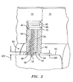
- FIG. 2 shows further details of the exemplary sealing system 40.
- the system includes a brush seal assembly 50 having a bristle pack 52 secured in a seal body comprising a pair of backing plates 54 and 56 sandwiching the bristle pack on respective high and low pressure sides thereof.
- the bristle roots are secured between the plates with bristle tips 58 extending inward therefrom to contact the shaft outer surface 60.
- the plates 54 and 56 are respectively designated as the side plate and the backplate and sandwich the bristle pack on respective high and low pressure sides thereof.
- Bristle and plate materials are typically various metal alloys such as nickel- or cobalt-based superalloys and the plates and bristle roots may thus be secured by welding.
- Additional, shorter bristles may intervene between the sealing bristles contacting the shaft and the backplate.
- the tips of these bristles may be closer to the rotor than is the inboard surface of the backplate. Such an arrangement provides additional support to the sealing bristles during true running operation while limiting the chance of damage during a rotor excursion.
- a rubplate 62 is secured on the low pressure side of the backing plate 56.
- the seal assembly rides in a radially inwardly-open channel of compartment 70 formed between sections 72 and 74 of the case.
- a wave spring 80 is positioned between an outer base surface 82 of the compartment 70 and the outer peripheral surface 84 of the seal assembly which, in the exemplary embodiment is formed by outer surface portions of the backing plates, rubplate, and bristle pack.
- the spring 80 serves to bias the seal assembly toward a coaxial relation with the case.
- the inboardmost surfaces 90, 92 and 94 of the backing plates 54 and 56 and rubplate 62, respectively are in close facing relation to the shaft surface 60.
- the surface 94 has a true radial clearance 520 relative to the surface 60 which is smaller than the clearances of the surfaces 90 and 92, (shown in the exemplary embodiment as a single clearance 522).
- the exemplary clearance 520 may advantageously be between 20% and 90% (more narrowly, 20% and 50%) of a lesser of the clearances of the surfaces 90 and 92).
- the rubplate radial clearance may advantageously be between 0.02 and 0.09 inch (0.5 and 2.29 mm).
- the shaft the plates 54 and 56 are made of a nickel-based superalloy while the rubplate is made of a galling-resistant austenitic stainless steel and the adjacent portion of the shaft is a coated nickel alloy.
- the plates 54 and 56 may be formed of a nickel-chromium-molybdenum-niobium alloy that is highly resistant to corrosion and is age hardenable for extremely high strength (e.g., UNS N06625 or UNS N07718).
- the rubplate in turn, may be formed of UNS S21800 (carbon 0.1 max, chromium 16 - 18, iron balance, manganese 7 - 9, nickel 8 - 9, nitrogen 0.08 - 0.18, phosphorus 0.04 max, silicon 3.5 - 4.5, sulphur 0.03 max weight percent).
- the rubplate inboardmost surface 94 advantageously has a smooth surface (e.g., finished to 32 ⁇ in. or below) as does the adjacent portion of the shaft outer surface 60.
- a radial excursion of the shaft axis relative to the housing axis will apply a net force to the bristles.
- the bristles may apply a slight resistance to the radial excursion, it may slightly shift the seal against the centering force of the wave spring 80, the excursion may be sufficient to bring the shaft outer surface 60 into contact with the rubplate inboard inboardmost surface 94. The contact will cause the seal to shift against the centering force of the wave spring to prevent further deformation of the bristles.
- the rubplate 62 (or at least its inboardmost contacting portion) has a good tribological match with the material of the shaft (or at least the contacting portion thereof). This low friction interaction may be achieved via use of dissimilar materials for the rubplate and shaft.
- rubplate material may be selected to avoid transfer to the shaft (e.g., smearing) some degree of smearing may be acceptable as not interfering with performance.
- the use of the rubplate may have any of a number of advantages.
- the rubplate can be chosen as a good tribological match with the shaft.
- contact between the low pressure side backing plate and the rotor may create a burr on the backing plate which then is contacted by the bristles, cutting the bristles and decreasing sealing.
- fricitional interaction between the brushpack and rotor during excursions may excessively wear the brushpack and may frictionally heat the rotor causing the rotor to expand and, thereby, yet further increase the likelihood of interference and friction.
- the reduced clearance of the rubplate compared with the backing plate may itself further reduce seal leakage.
- Such seals may be used in retrofit or redesign situations. In such situations other features of the seal may remain constant or may change.
- the replacement seal's plates' radial clearances may be respectively smaller than the original seal's plates' radial clearances.
Landscapes
- Engineering & Computer Science (AREA)
- General Engineering & Computer Science (AREA)
- Mechanical Engineering (AREA)
- Sealing Devices (AREA)
- Turbine Rotor Nozzle Sealing (AREA)
Abstract
Description
- This invention relates to shaft seals, and more particularly to turbine engine shaft seals.
- In turbomachinery applications, it is often necessary to provide a seal between a rotating shaft and a housing element. At the seal, the shaft typically has symmetry around a central axis (e.g., the shaft has a cylindrical surface area). The shaft axis is normally coincident with the axis of rotation and with an axis of the housing in which the seal is mounted. However, vibration may induce small local oscillatory excursions of the axis of rotation. Brush and labyrinth seals may have sufficient compliance or clearance in their respective bristle packs and labyrinth teeth to accommodate relatively minor excursions. To accommodate greater excursions, there may be a non-rigid mounting of the seal element to the housing. This mounting permits excursions of the shaft axis to radially shift the seal relative to the housing to avoid damage to the seal.
- A turbine engine has a rotor shaft rotatably carried within a support structure. A seal is carried by the support structure circumscribing the shaft and having a brushpack for sealing with the shaft. A first plate on a first side of the brushpack has a first radial clearance from the rotor shaft. A rubplate has a radial clearance from the rotor shaft that is less than the first radial clearance when the seal and rotor are coaxial. The seal may be a full annulus or may be segmented. A biasing member may be located between the seal and support structure.
- The details of one or more embodiments of the invention are set forth in the accompanying drawings and the description below. Other features and advantages of the invention will be apparent from the description and drawings, and from the claims.
-
- FIG. 1 is a longitudinal semi-schematic sectional view of a turbine engine.
- FIG. 2 is a partial semi-schematic longitudinal sectional view of a seal system of the engine of FIG. 1.
-
- Like reference numbers and designations in the various drawings indicate like elements.
- FIG. 1 shows a
turbine engine 20 having ahousing case 22 containing concentric high and lowpressure rotor shafts axis 500 which is normally coincident with central longitudinal axes of the housing and shafts. The highpressure rotor shaft 24 is driven by the blades of a highpressure turbine section 26 to in turn drive the blades of ahigh pressure compressor 27. The lowpressure rotor shaft 25 is driven by the blades of a lowpressure turbine section 28 to in turn drive the blades of a lowpressure compressor section 29 and afan 30. - The rotor shafts are supported relative to the case by a number of bearing systems. The rotor shafts may be sealed relative to the case by
sealing systems 40 which may include brush sealing elements, labyrinth sealing elements, or the like. The illustrated seal locations are exemplary. Other locations are possible, including interstage locations within the turbine and compressor (between rotating blade "wheels"). - FIG. 2 shows further details of the
exemplary sealing system 40. The system includes abrush seal assembly 50 having abristle pack 52 secured in a seal body comprising a pair ofbacking plates bristle tips 58 extending inward therefrom to contact the shaftouter surface 60. Theplates - A
rubplate 62 is secured on the low pressure side of thebacking plate 56. The seal assembly rides in a radially inwardly-open channel ofcompartment 70 formed betweensections wave spring 80 is positioned between anouter base surface 82 of thecompartment 70 and the outerperipheral surface 84 of the seal assembly which, in the exemplary embodiment is formed by outer surface portions of the backing plates, rubplate, and bristle pack. Thespring 80 serves to bias the seal assembly toward a coaxial relation with the case. In the exemplary embodiment, theinboardmost surfaces backing plates rubplate 62, respectively are in close facing relation to theshaft surface 60. In the exemplary embodiment, thesurface 94 has a trueradial clearance 520 relative to thesurface 60 which is smaller than the clearances of thesurfaces exemplary clearance 520 may advantageously be between 20% and 90% (more narrowly, 20% and 50%) of a lesser of the clearances of thesurfaces 90 and 92). For example, with the latter clearances each in a range of between 0.025 and 0.100 inch (0.635 and 2.54 mm), the rubplate radial clearance may advantageously be between 0.02 and 0.09 inch (0.5 and 2.29 mm). - In an exemplary embodiment, the shaft the
plates plates inboardmost surface 94 advantageously has a smooth surface (e.g., finished to 32µin. or below) as does the adjacent portion of the shaftouter surface 60. - In operation, a radial excursion of the shaft axis relative to the housing axis will apply a net force to the bristles. Although the bristles may apply a slight resistance to the radial excursion, it may slightly shift the seal against the centering force of the
wave spring 80, the excursion may be sufficient to bring the shaftouter surface 60 into contact with the rubplate inboardinboardmost surface 94. The contact will cause the seal to shift against the centering force of the wave spring to prevent further deformation of the bristles. Advantageously, the rubplate 62 (or at least its inboardmost contacting portion) has a good tribological match with the material of the shaft (or at least the contacting portion thereof). This low friction interaction may be achieved via use of dissimilar materials for the rubplate and shaft. The use of dissimilar materials may also provide an advantageous sacrificial nature of the rubplate so that it does not score or otherwise wear the shaft but is itself worn by the shaft (as rubplate or seal replacement may be substantially less expensive than shaft replacement). Although rubplate material may be selected to avoid transfer to the shaft (e.g., smearing) some degree of smearing may be acceptable as not interfering with performance. - Depending on any particular implementation, the use of the rubplate may have any of a number of advantages. When the desired shaft and backing plate materials are not good tribological matches, the rubplate can be chosen as a good tribological match with the shaft. Additionally, in the absence of a rubplate, contact between the low pressure side backing plate and the rotor may create a burr on the backing plate which then is contacted by the bristles, cutting the bristles and decreasing sealing. Additionally, in the absence of the rubplate and with sufficient backing plate clearance, fricitional interaction between the brushpack and rotor during excursions may excessively wear the brushpack and may frictionally heat the rotor causing the rotor to expand and, thereby, yet further increase the likelihood of interference and friction. Also, the reduced clearance of the rubplate compared with the backing plate may itself further reduce seal leakage.
- Such seals may be used in retrofit or redesign situations. In such situations other features of the seal may remain constant or may change. For example the replacement seal's plates' radial clearances may be respectively smaller than the original seal's plates' radial clearances.
- One or more embodiments of the present invention have been described. Nevertheless, it will be understood that various modifications may be made without departing from the spirit and scope of the invention. For example, the principles may be applied to various existing and future seal constructions. Particularly in retrofit or redesign situations, details of the existing seal and its environment may influence any particular implementation. Additional features are possible such as a seal anti-rotation features (e.g., radial pins or tabs mounted to the seal and riding in slots in the case). Accordingly, other embodiments are within the scope of the following claims.
Claims (14)
- A turbine engine comprising:a support structure (22) having a first axis;a rotor shaft (25) having a rotor axis (500) and rotatably carried by the support structure;a seal (40) having:a seal axis, the seal being carried by the support structure circumscribing the shaft so as to permit radial excursions of the seal axis from the first axis;a brushpack (52) in contact with the rotor shaft and having first and second sides;at least a first plate (90) on the first side of the brushpack and having a first radial clearance (522) from the rotor shaft when said seal axis and rotor axis coincide; anda rubplate element (62) on one of said first and second sides of the brushpack and having a rubplate radial clearance (520) from the rotor shaft that is less than the first radial clearance when said seal axis and rotor axis coincide, the rubplate having a portion softer than an adjacent portion of the rotor shaft.
- The engine of claim 1 wherein said rubplate portion (94) is formed of a stainless steel.
- The engine of claim 1 or 2 further comprising a fan (30) carried by the rotor shaft (25).
- The engine of any preceding claim wherein the first side is a low pressure side and wherein the seal further comprises:a second plate (92) on the second side of the brushpack (52) and having a second radial clearance from the rotor shaft (25) when said seal axis and rotor axis coincide, the second plate (92) positioned between the rubplate element (62) and the brushpack (52).
- The engine of claim 4 wherein:said first radial clearance is between 0.025 and 0.100 inch (0.635 and 2.54 mm);said second radial clearance is between 0.025 and 0.100 inch (0.635 and 2.54 mm);said rubplate radial clearance is between 0.020 and 0.090 inch (0.5 and 2.29 mm).
- The engine of claim 4 wherein said rubplate radial clearance (520) is between 20% and 50% of a lesser of said first radial clearance and said second radial clearance (522).
- The engine of any preceding claim further comprising a wave spring (80) positioned radially between the seal and a base surface (82) of a seal compartment (70) of the support structure and biasing the seal toward a coaxial relation with the support structure.
- A sealing system comprising:a first structure (22) having an axis;a second structure (25) having an axis (500) and rotatable relative to the first structure; anda seal (40):circumscribing the second structure within the first structure;having a seal axis;carried by a support on one of the first and second structures;having a brushpack (52) for sealing with the other of the first and second structure; andhaving first and second backing plates (90,92) on first and second sides of the brushpack (52), the first and second backing plates respectively having first and second radial clearances (522) from said other structure when the seal and the other structure are coaxial; anda rubplate (62) having a third radial clearance (520) from said other structure when the seal and the other structure are coaxial, the third clearance (520) being less than first and second clearances (522).
- The system of claim 8 wherein an inboardmost portion (94) of the rubplate (62) is softer than an adjacent surface portion (60) of said other structure (25).
- The system of claim 8 or 9 wherein:said support structure (22) is said first structure; andthe second structure (25) is rotatably carried by the first structure.
- The system of claim 8, 9 or 10 wherein the rubplate (52) consists essentially of steel and an adjacent portion (60) of said other structure consists essentially of a nickel- or cobalt-based superalloy.
- With a turbomachine having:a method for servicing the turbomachine comprising:a support structure (22) having a first axis;a rotor shaft (25) having a rotor axis (500) and rotatably carried by the support structure;a first seal (40) having:a seal axis, the seal being carried by the support structure circumscribing the shaft so as to permit radial excursions of the seal axis from the first axis;a brushpack in contact with the rotor shaft and having first and second sides;first and second backing plates on first and second sides of the brushpack, the first and second backing plates respectively having first and second radial clearances from said other structure when the seal axis and rotor axis coincide;replacing the first seal with a second seal, the second seal, when installed, having:a seal axis;a brushpack (52) in contact with the rotor shaft and having first and second sides;at least a first plate (90) on the first side of the second seal brushpack (52) and having a first radial clearance (522) from the rotor shaft when said second seal seal axis and rotor axis coincide;a rubplate element (62) on one of said first and second sides of the second seal brushpack and having a rubplate radial clearance (520) from the rotor shaft (25) that is less than the first radial clearance (522) when said second seal seal axis and rotor axis coincide, the rubplate (62) having an inboard portion (94) formed of a material softer than the material of inboard portions of the at least first seal backing plates (90) and softer than an adjacent portion (60) of the rotor shaft (25).
- The method of claim 12 wherein the second seal comprises first and second plates (90,92) on respective sides of said second seal brushpack and each having respective radial clearances and wherein the second seal first and second radial clearances are respectively smaller than the first seal first and second radial clearances.
- A turbine engine comprising:a support structure (22) having a first axis;a rotor shaft (25) having a rotor axis (500) and rotatably carried by the support structure;a seal (40) having:a seal axis, the seal being carried by the support structure circumscribing the shaft so as to permit radial excursions of the seal axis from the first axis;a brushpack (52) in contact with the rotor shaft and having first and second sides;at least a first plate (90) on the first side of the brushpack and having a first radial clearance (522) from the rotor shaft when said seal axis and rotor axis coincide; anda rubplate element (62) on one of said first and second sides of the brushpack and having a rubplate radial clearance (520) from the rotor shaft that is less than the first radial clearance when said seal axis and rotor axis coincide.
Applications Claiming Priority (2)
| Application Number | Priority Date | Filing Date | Title |
|---|---|---|---|
| US10/330,752 US6910858B2 (en) | 2002-12-26 | 2002-12-26 | Seal |
| US330752 | 2002-12-26 |
Publications (2)
| Publication Number | Publication Date |
|---|---|
| EP1433928A2 true EP1433928A2 (en) | 2004-06-30 |
| EP1433928A3 EP1433928A3 (en) | 2006-09-20 |
Family
ID=32469047
Family Applications (1)
| Application Number | Title | Priority Date | Filing Date |
|---|---|---|---|
| EP03257867A Withdrawn EP1433928A3 (en) | 2002-12-26 | 2003-12-15 | Brush seal for a turbomachine |
Country Status (2)
| Country | Link |
|---|---|
| US (1) | US6910858B2 (en) |
| EP (1) | EP1433928A3 (en) |
Cited By (2)
| Publication number | Priority date | Publication date | Assignee | Title |
|---|---|---|---|---|
| EP1734230A1 (en) * | 2005-06-13 | 2006-12-20 | Siemens Aktiengesellschaft | Turbomachine |
| WO2011139741A3 (en) * | 2010-05-03 | 2012-04-05 | Elliott Company | Brush ring seal |
Families Citing this family (5)
| Publication number | Priority date | Publication date | Assignee | Title |
|---|---|---|---|---|
| DE10259381A1 (en) * | 2002-12-18 | 2004-07-15 | Mtu Aero Engines Gmbh | sealing arrangement |
| GB2407626A (en) * | 2003-10-31 | 2005-05-04 | Rolls Royce Plc | Suspended seal arrangement |
| US8505923B2 (en) * | 2009-08-31 | 2013-08-13 | Sealeze, A Unit of Jason, Inc. | Brush seal with stress and deflection accommodating membrane |
| US8657298B2 (en) * | 2011-08-15 | 2014-02-25 | General Electric Company | Brush seal with backing plate tooth |
| US9863538B2 (en) | 2015-04-27 | 2018-01-09 | United Technologies Corporation | Gas turbine engine brush seal with supported tip |
Citations (4)
| Publication number | Priority date | Publication date | Assignee | Title |
|---|---|---|---|---|
| US5351971A (en) | 1993-05-21 | 1994-10-04 | Eg&G Sealol, Inc. | Brush seal device having a floating backplate |
| US5474305A (en) | 1990-09-18 | 1995-12-12 | Cross Manufacturing Company (1938) Limited | Sealing device |
| US5630590A (en) | 1996-03-26 | 1997-05-20 | United Technologies Corporation | Method and apparatus for improving the airsealing effectiveness in a turbine engine |
| US6079945A (en) | 1997-11-10 | 2000-06-27 | Geneal Electric Company | Brush seal for high-pressure rotor applications |
Family Cites Families (14)
| Publication number | Priority date | Publication date | Assignee | Title |
|---|---|---|---|---|
| GB1316452A (en) * | 1970-08-14 | 1973-05-09 | Secr Defence | Gas turbine engine |
| GB9008917D0 (en) * | 1990-04-20 | 1990-06-20 | Cross Mfg Co | Brush seals |
| US5201530A (en) | 1991-10-18 | 1993-04-13 | United Technologies Corporation | Multi-layered brush seal |
| US5308088A (en) * | 1992-08-20 | 1994-05-03 | General Electric Company | Brush seal with flexible backing plate |
| US5335920A (en) * | 1992-08-20 | 1994-08-09 | General Electric Company | Brush seal |
| US5452957A (en) | 1994-11-22 | 1995-09-26 | Dana Corporation | Center bearing assembly including support member containing rheological fluid |
| DE19529655C2 (en) * | 1995-08-11 | 1999-04-22 | Mtu Muenchen Gmbh | Brush seal for turbomachinery |
| US5599026A (en) * | 1995-09-06 | 1997-02-04 | Innovative Technology, L.L.C. | Turbine seal with sealing strip and rubbing strip |
| US6318728B1 (en) | 1997-07-11 | 2001-11-20 | Demag Delaval Turbomachinery Corporation | Brush-seal designs for elastic fluid turbines |
| US6168162B1 (en) * | 1998-08-05 | 2001-01-02 | General Electric Co. | Self-centering brush seal |
| GB9900102D0 (en) * | 1999-01-06 | 1999-02-24 | Rolls Royce Plc | A seal arrangement |
| US6302646B1 (en) * | 1999-12-15 | 2001-10-16 | General Electric Company | Rotary machine containing a brush seal |
| US6382632B1 (en) * | 2001-02-21 | 2002-05-07 | General Electric Company | Repositionable brush seal for turbomachinery |
| JP4689882B2 (en) * | 2001-06-29 | 2011-05-25 | イーグル工業株式会社 | Plate brush seal device |
-
2002
- 2002-12-26 US US10/330,752 patent/US6910858B2/en not_active Expired - Lifetime
-
2003
- 2003-12-15 EP EP03257867A patent/EP1433928A3/en not_active Withdrawn
Patent Citations (4)
| Publication number | Priority date | Publication date | Assignee | Title |
|---|---|---|---|---|
| US5474305A (en) | 1990-09-18 | 1995-12-12 | Cross Manufacturing Company (1938) Limited | Sealing device |
| US5351971A (en) | 1993-05-21 | 1994-10-04 | Eg&G Sealol, Inc. | Brush seal device having a floating backplate |
| US5630590A (en) | 1996-03-26 | 1997-05-20 | United Technologies Corporation | Method and apparatus for improving the airsealing effectiveness in a turbine engine |
| US6079945A (en) | 1997-11-10 | 2000-06-27 | Geneal Electric Company | Brush seal for high-pressure rotor applications |
Cited By (3)
| Publication number | Priority date | Publication date | Assignee | Title |
|---|---|---|---|---|
| EP1734230A1 (en) * | 2005-06-13 | 2006-12-20 | Siemens Aktiengesellschaft | Turbomachine |
| WO2011139741A3 (en) * | 2010-05-03 | 2012-04-05 | Elliott Company | Brush ring seal |
| US9347333B2 (en) | 2010-05-03 | 2016-05-24 | Elliott Company | Brush ring seal |
Also Published As
| Publication number | Publication date |
|---|---|
| US6910858B2 (en) | 2005-06-28 |
| US20040126227A1 (en) | 2004-07-01 |
| EP1433928A3 (en) | 2006-09-20 |
Similar Documents
| Publication | Publication Date | Title |
|---|---|---|
| CA2536362C (en) | Hydrodynamic brush seal | |
| JP4049865B2 (en) | Turbine blade integrated damper seal | |
| US10087763B2 (en) | Damper for an integrally bladed rotor | |
| EP1672256B1 (en) | Clamp lock and brush seal assembly | |
| JP6063245B2 (en) | Change in grindability of turbine engine seals | |
| WO2008094761A1 (en) | Hydrodynamic brush seal | |
| EP0453315A1 (en) | Brush seals | |
| EP2233800A1 (en) | Seal member, assembly and method | |
| JP2013079719A (en) | Foil bearing | |
| US6910858B2 (en) | Seal | |
| US8282356B2 (en) | Apparatus and method for reducing wear in disk lugs | |
| EP1424518B1 (en) | Brush seal with adjustable clearance | |
| EP3409885B1 (en) | Deflection spring seal | |
| EP1433927B1 (en) | Turbine engine and seal | |
| JPS62131930A (en) | Shaft seal apparatus to turbo machine, especially, multiaxisgas turbine engine | |
| EP1790833A2 (en) | Bearing arrangement for a gas turbine | |
| EP1712743A2 (en) | Turbine with an abradable seal between the rotor and a stationary component | |
| CN113614402B (en) | Thrust foil bearing, foil bearing unit, turbomachine and foil | |
| EP3401508A1 (en) | Insulated seal seat | |
| EP3385553A1 (en) | Foil bearing | |
| US6863509B2 (en) | Split seal plate with integral brush seal | |
| EP3907377B1 (en) | Reduced radial clearance seal system | |
| US11313280B2 (en) | Gas turbine engine including seal assembly with abradable coating and cutter | |
| EP3783249B1 (en) | Non-contact seal with axial arrangement | |
| EP3851634B1 (en) | Seal element for sealing a joint between a rotor blade and a rotor disk of a turbine engine |
Legal Events
| Date | Code | Title | Description |
|---|---|---|---|
| PUAI | Public reference made under article 153(3) epc to a published international application that has entered the european phase |
Free format text: ORIGINAL CODE: 0009012 |
|
| AK | Designated contracting states |
Kind code of ref document: A2 Designated state(s): AT BE BG CH CY CZ DE DK EE ES FI FR GB GR HU IE IT LI LU MC NL PT RO SE SI SK TR |
|
| AX | Request for extension of the european patent |
Extension state: AL LT LV MK |
|
| PUAL | Search report despatched |
Free format text: ORIGINAL CODE: 0009013 |
|
| AK | Designated contracting states |
Kind code of ref document: A3 Designated state(s): AT BE BG CH CY CZ DE DK EE ES FI FR GB GR HU IE IT LI LU MC NL PT RO SE SI SK TR |
|
| AX | Request for extension of the european patent |
Extension state: AL LT LV MK |
|
| 17P | Request for examination filed |
Effective date: 20070312 |
|
| AKX | Designation fees paid |
Designated state(s): DE FR GB |
|
| 17Q | First examination report despatched |
Effective date: 20070626 |
|
| STAA | Information on the status of an ep patent application or granted ep patent |
Free format text: STATUS: THE APPLICATION IS DEEMED TO BE WITHDRAWN |
|
| 18D | Application deemed to be withdrawn |
Effective date: 20140103 |