EP1433748A2 - Process and production reactor for the preparation of nitrogen trifluoride - Google Patents
Process and production reactor for the preparation of nitrogen trifluoride Download PDFInfo
- Publication number
- EP1433748A2 EP1433748A2 EP03258137A EP03258137A EP1433748A2 EP 1433748 A2 EP1433748 A2 EP 1433748A2 EP 03258137 A EP03258137 A EP 03258137A EP 03258137 A EP03258137 A EP 03258137A EP 1433748 A2 EP1433748 A2 EP 1433748A2
- Authority
- EP
- European Patent Office
- Prior art keywords
- reaction zone
- reaction
- fluorine gas
- gas
- aspect ratio
- Prior art date
- Legal status (The legal status is an assumption and is not a legal conclusion. Google has not performed a legal analysis and makes no representation as to the accuracy of the status listed.)
- Withdrawn
Links
Images
Classifications
-
- B—PERFORMING OPERATIONS; TRANSPORTING
- B01—PHYSICAL OR CHEMICAL PROCESSES OR APPARATUS IN GENERAL
- B01J—CHEMICAL OR PHYSICAL PROCESSES, e.g. CATALYSIS OR COLLOID CHEMISTRY; THEIR RELEVANT APPARATUS
- B01J8/00—Chemical or physical processes in general, conducted in the presence of fluids and solid particles; Apparatus for such processes
- B01J8/02—Chemical or physical processes in general, conducted in the presence of fluids and solid particles; Apparatus for such processes with stationary particles, e.g. in fixed beds
- B01J8/06—Chemical or physical processes in general, conducted in the presence of fluids and solid particles; Apparatus for such processes with stationary particles, e.g. in fixed beds in tube reactors; the solid particles being arranged in tubes
-
- C—CHEMISTRY; METALLURGY
- C01—INORGANIC CHEMISTRY
- C01B—NON-METALLIC ELEMENTS; COMPOUNDS THEREOF; METALLOIDS OR COMPOUNDS THEREOF NOT COVERED BY SUBCLASS C01C
- C01B21/00—Nitrogen; Compounds thereof
- C01B21/082—Compounds containing nitrogen and non-metals and optionally metals
- C01B21/083—Compounds containing nitrogen and non-metals and optionally metals containing one or more halogen atoms
-
- B—PERFORMING OPERATIONS; TRANSPORTING
- B01—PHYSICAL OR CHEMICAL PROCESSES OR APPARATUS IN GENERAL
- B01F—MIXING, e.g. DISSOLVING, EMULSIFYING OR DISPERSING
- B01F25/00—Flow mixers; Mixers for falling materials, e.g. solid particles
- B01F25/50—Circulation mixers, e.g. wherein at least part of the mixture is discharged from and reintroduced into a receptacle
- B01F25/53—Circulation mixers, e.g. wherein at least part of the mixture is discharged from and reintroduced into a receptacle in which the mixture is discharged from and reintroduced into a receptacle through a recirculation tube, into which an additional component is introduced
-
- B—PERFORMING OPERATIONS; TRANSPORTING
- B01—PHYSICAL OR CHEMICAL PROCESSES OR APPARATUS IN GENERAL
- B01F—MIXING, e.g. DISSOLVING, EMULSIFYING OR DISPERSING
- B01F33/00—Other mixers; Mixing plants; Combinations of mixers
- B01F33/80—Mixing plants; Combinations of mixers
- B01F33/82—Combinations of dissimilar mixers
- B01F33/821—Combinations of dissimilar mixers with consecutive receptacles
- B01F33/8212—Combinations of dissimilar mixers with consecutive receptacles with moving and non-moving stirring devices
-
- B—PERFORMING OPERATIONS; TRANSPORTING
- B01—PHYSICAL OR CHEMICAL PROCESSES OR APPARATUS IN GENERAL
- B01J—CHEMICAL OR PHYSICAL PROCESSES, e.g. CATALYSIS OR COLLOID CHEMISTRY; THEIR RELEVANT APPARATUS
- B01J19/00—Chemical, physical or physico-chemical processes in general; Their relevant apparatus
- B01J19/0053—Details of the reactor
- B01J19/006—Baffles
-
- B—PERFORMING OPERATIONS; TRANSPORTING
- B01—PHYSICAL OR CHEMICAL PROCESSES OR APPARATUS IN GENERAL
- B01J—CHEMICAL OR PHYSICAL PROCESSES, e.g. CATALYSIS OR COLLOID CHEMISTRY; THEIR RELEVANT APPARATUS
- B01J19/00—Chemical, physical or physico-chemical processes in general; Their relevant apparatus
- B01J19/0053—Details of the reactor
- B01J19/0066—Stirrers
-
- B—PERFORMING OPERATIONS; TRANSPORTING
- B01—PHYSICAL OR CHEMICAL PROCESSES OR APPARATUS IN GENERAL
- B01J—CHEMICAL OR PHYSICAL PROCESSES, e.g. CATALYSIS OR COLLOID CHEMISTRY; THEIR RELEVANT APPARATUS
- B01J19/00—Chemical, physical or physico-chemical processes in general; Their relevant apparatus
- B01J19/18—Stationary reactors having moving elements inside
- B01J19/1868—Stationary reactors having moving elements inside resulting in a loop-type movement
- B01J19/1881—Stationary reactors having moving elements inside resulting in a loop-type movement externally, i.e. the mixture leaving the vessel and subsequently re-entering it
-
- B—PERFORMING OPERATIONS; TRANSPORTING
- B01—PHYSICAL OR CHEMICAL PROCESSES OR APPARATUS IN GENERAL
- B01J—CHEMICAL OR PHYSICAL PROCESSES, e.g. CATALYSIS OR COLLOID CHEMISTRY; THEIR RELEVANT APPARATUS
- B01J19/00—Chemical, physical or physico-chemical processes in general; Their relevant apparatus
- B01J19/24—Stationary reactors without moving elements inside
- B01J19/2415—Tubular reactors
- B01J19/2425—Tubular reactors in parallel
-
- C—CHEMISTRY; METALLURGY
- C01—INORGANIC CHEMISTRY
- C01B—NON-METALLIC ELEMENTS; COMPOUNDS THEREOF; METALLOIDS OR COMPOUNDS THEREOF NOT COVERED BY SUBCLASS C01C
- C01B21/00—Nitrogen; Compounds thereof
- C01B21/082—Compounds containing nitrogen and non-metals and optionally metals
- C01B21/083—Compounds containing nitrogen and non-metals and optionally metals containing one or more halogen atoms
- C01B21/0832—Binary compounds of nitrogen with halogens
- C01B21/0835—Nitrogen trifluoride
-
- B—PERFORMING OPERATIONS; TRANSPORTING
- B01—PHYSICAL OR CHEMICAL PROCESSES OR APPARATUS IN GENERAL
- B01F—MIXING, e.g. DISSOLVING, EMULSIFYING OR DISPERSING
- B01F25/00—Flow mixers; Mixers for falling materials, e.g. solid particles
- B01F25/40—Static mixers
- B01F25/42—Static mixers in which the mixing is affected by moving the components jointly in changing directions, e.g. in tubes provided with baffles or obstructions
-
- B—PERFORMING OPERATIONS; TRANSPORTING
- B01—PHYSICAL OR CHEMICAL PROCESSES OR APPARATUS IN GENERAL
- B01F—MIXING, e.g. DISSOLVING, EMULSIFYING OR DISPERSING
- B01F27/00—Mixers with rotary stirring devices in fixed receptacles; Kneaders
- B01F27/80—Mixers with rotary stirring devices in fixed receptacles; Kneaders with stirrers rotating about a substantially vertical axis
-
- B—PERFORMING OPERATIONS; TRANSPORTING
- B01—PHYSICAL OR CHEMICAL PROCESSES OR APPARATUS IN GENERAL
- B01J—CHEMICAL OR PHYSICAL PROCESSES, e.g. CATALYSIS OR COLLOID CHEMISTRY; THEIR RELEVANT APPARATUS
- B01J2219/00—Chemical, physical or physico-chemical processes in general; Their relevant apparatus
- B01J2219/00002—Chemical plants
- B01J2219/00004—Scale aspects
- B01J2219/00006—Large-scale industrial plants
-
- B—PERFORMING OPERATIONS; TRANSPORTING
- B01—PHYSICAL OR CHEMICAL PROCESSES OR APPARATUS IN GENERAL
- B01J—CHEMICAL OR PHYSICAL PROCESSES, e.g. CATALYSIS OR COLLOID CHEMISTRY; THEIR RELEVANT APPARATUS
- B01J2219/00—Chemical, physical or physico-chemical processes in general; Their relevant apparatus
- B01J2219/00002—Chemical plants
- B01J2219/00027—Process aspects
- B01J2219/0004—Processes in series
-
- B—PERFORMING OPERATIONS; TRANSPORTING
- B01—PHYSICAL OR CHEMICAL PROCESSES OR APPARATUS IN GENERAL
- B01J—CHEMICAL OR PHYSICAL PROCESSES, e.g. CATALYSIS OR COLLOID CHEMISTRY; THEIR RELEVANT APPARATUS
- B01J2219/00—Chemical, physical or physico-chemical processes in general; Their relevant apparatus
- B01J2219/00049—Controlling or regulating processes
- B01J2219/00051—Controlling the temperature
- B01J2219/00074—Controlling the temperature by indirect heating or cooling employing heat exchange fluids
- B01J2219/00076—Controlling the temperature by indirect heating or cooling employing heat exchange fluids with heat exchange elements inside the reactor
- B01J2219/00085—Plates; Jackets; Cylinders
-
- B—PERFORMING OPERATIONS; TRANSPORTING
- B01—PHYSICAL OR CHEMICAL PROCESSES OR APPARATUS IN GENERAL
- B01J—CHEMICAL OR PHYSICAL PROCESSES, e.g. CATALYSIS OR COLLOID CHEMISTRY; THEIR RELEVANT APPARATUS
- B01J2219/00—Chemical, physical or physico-chemical processes in general; Their relevant apparatus
- B01J2219/00049—Controlling or regulating processes
- B01J2219/00245—Avoiding undesirable reactions or side-effects
- B01J2219/00247—Fouling of the reactor or the process equipment
-
- C—CHEMISTRY; METALLURGY
- C01—INORGANIC CHEMISTRY
- C01P—INDEXING SCHEME RELATING TO STRUCTURAL AND PHYSICAL ASPECTS OF SOLID INORGANIC COMPOUNDS
- C01P2006/00—Physical properties of inorganic compounds
- C01P2006/80—Compositional purity
Definitions
- the present invention relates generally to nitrogen trifluoride and more particularly to a reactor system and a method for the production of nitrogen trifluoride from ammonia, elemental fluorine, and liquid ammonium acid fluoride.
- Nitrogen trifluoride (NF 3 ) has been employed for such products as high energy liquid and solid propellants and as a fluorine source for the production of semiconductor devices.
- Nitrogen fluoride can be prepared by a variety of processes such as disclosed in U.S. Patent Nos. 4,091,081 and 5,637,285 and U.S. Patent Publication No. 2002/0127167 each of which is incorporated herein by reference.
- the production of nitrogen trifluoride generally results from a series of reactions as described below in which ammonia and fluorine gas are combined with a liquid ammonium acid fluoride intermediate.
- Reaction 1 represents the desired NF 3 production reaction.
- Reaction 2 is the most rapid undesirable side reaction.
- Reaction 3 represents the fluorine gas that does not react.
- Reaction 3 c 3 F 2 (g) ⁇ c 3 F 2 (g)
- the c 1 and c 2 values are the estimated fractions of the fluorine feed that react to produce respectively, the desired NF 3 product and the undesirable N 2 by-product.
- the c 3 fraction represents the fluorine gas that does not react.
- the NH 4 F(HF) x melt acidity x value is the molar ratio of hydrogen fluoride to ammonia minus one in the melt.
- the ⁇ value is the ratio of the actual liquid ammonia acid fluoride melt [NH 4 F(HF) x] feed rate to the minimum stoichiometric NH 4 F(HF) x feed rate.
- the temperature of the reaction zone is moderated by using excess NH 4 F(HF) x . This simplified process representation neglects other factors, e.g. the small fraction of HF in the crude NF 3 vapor product.
- United States Patent No. 4,091,081 discloses the production of NF 3 by sparging fluorine and ammonia into liquid ammonium acid fluoride in a column.
- United States Patent No. 5,637,285 discloses that simultaneously increasing the hydrogen fluoride content of the ammonium acid fluoride melt and increasing the mixing intensity increases the F 2 -to-NF 3 conversion rate.
- increasing the NH 4 F(HF) x melt acidity "x" value decreases the rate of Reaction 2 relative to Reaction 1 which tends to increase the overall NF 3 yield.
- higher NH 4 F(HF) x melt acidity "x” values also somewhat decrease the rate of NF 3 production via Reaction 1 for a given interfacial surface area.
- United States Patent Application Publication No. US/2002/0127167 A1 employs the advantages of higher mixing intensity as disclosed in United States Patent No. 5,637,285 and higher circulation rate to increase the effective ⁇ value to decrease localized overheating, increase F 2 -to-NF 3 conversion (c 1 ), and decrease the impeller corrosion.
- this approach does not address the issue concerning the impeller shaft length or the combination of high mixing rates and high fluorine concentration.
- the NH 4 F(HF) x melt recirculation rate is limited by gaseous product flow rate and gas-liquid separation.
- the present invention is generally directed to the production of NF 3 by reacting fluorine gas, ammonia gas and liquid ammonium acid fluoride.
- the present invention provides a process in which low energy input is provided in vicinity of relatively high concentration of the corrosive reactant fluorine gas and higher energy input is provided in vicinity of relatively low concentrations of fluorine.
- a NF 3 producing system is provided with improved yields of NF 3 without excessive corrosion of the mixing assembly.
- the balancing of energy input and fluorine concentration creates a reaction environment that is less conducive to corrosion.
- the aspect ratio of the reaction zones and the power input supplied to the reaction zones are selected to construct reaction zones in which conditions which tend to cause corrosion (e.g. high shear rates, high energy input, and high concentration of fluorine gas) are balanced with conditions that tend to favor low corrosion (low shear rates, low energy input, and low concentrations of fluorine gas).
- the process is conducted in two reaction zones in which the first reaction zone is characterized by a relatively high aspect ratio and low power input and is the zone used to react fluorine gas at relatively high concentrations.
- the second reaction zone enables the process to proceed with a relatively low aspect ratio and high power input where the concentration of fluorine gas is relatively low because some of the fluorine gas has already reacted.
- a process for the production of NF 3 comprising:
- an impurity gas formed as part of the process of producing NF 3 which contains at least the impurities N 2 F 4 and NH 4 (HF) x are reacted with fluorine gas at elevated temperatures to convert at least some of the impurity to NF 3 and essentially completely removing the impurity.
- the present invention is directed to a process for producing NF 3 from a reaction mixture containing fluorine gas and liquid ammonium acid fluoride.
- the reaction is conducted in two reaction zones characterized as having different energy environments.
- the energy environment in the first reaction zone where the concentration of fluorine gas is relatively high is characterized as being a relatively low energy environment.
- the energy environment in the second reaction zone where the concentration of fluorine gas is less than the first reaction zone is characterized as being a relatively high energy environment.
- reaction conditions and/or structural conditions include, but are not limited to, the power input provided to the reaction zone and the aspect ratio of the reaction zone. Generally, higher power inputs and lower aspect ratios favor high energy environments while lower power inputs and higher aspect ratios favor low energy environments.
- the two reaction zones are characterized as having different aspect ratios with different power inputs.
- the aspect ratio is relatively high while mixing is conducted at a relatively low energy input such as the pressure which is applied to the fluorine gas feed to mix the fluorine gas with the other reactants in the presence of static structured mixing assemblies in which mixing is accomplished in the absence of moving parts.
- the aspect ratio of the reaction zone is reduced and the power input is increased so that a mixing assembly typically including an impeller may be used to mix the reactants.
- the effect of the present process is to overcome difficulties in obtaining effective yields of the desired product (NF 3 ) from a reaction which is characteristically highly exothermic, involves corrosive reactants and typically employs a mixing assembly generating high shear.
- the reaction of the fluorine gas with liquid ammonium acid fluoride melt and ammonia gas with the liquid ammonium acid fluoride is conducted in a system that is designed to minimize reaction between gaseous ammonia and fluorine and contains a mixing assembly typically including an impeller.
- the high heat, corrosive reactants and high shear rates generated from the reaction typically damages any protective layers (e.g. fluoride layers) on the impeller.
- the combination of high heat, corrosive reactants and high shear rates associated with the process assembly rapidly corrodes the impeller causing shut down of the process assembly and lost production time to replace the impeller.
- the present invention addresses the issue of impeller damage by conducting the process under conditions and in a manner which reduces and/or eliminates impeller damage.
- the term "aspect ratio" refers to the ratio of the length of a reaction zone to the width of the reaction zone.
- a reaction zone comprised of a cylindrical vessel having an aspect ratio of 2 will have a length twice as large as the width.
- an aspect ratio of 0.5 refers to a reaction zone having a length which is one half the width.
- the reaction zone aspect ratio is defined as the ratio of channel length to the channel hydraulic diameter.
- the hydraulic diameter for a channel or assembly of channels is defined as four times the channel cross sectional area divided by channel wall area per unit length.
- power input refers to the mechanical energy input to either reaction zone, but not energy transferred between the reaction zones.
- a mixer, pump, or compressed gas is used to input power to either reaction zone.
- the power input is measured in terms of Watts per cubic meter of the total NH 4 F(HF) x melt volume in the first and second reaction zones.
- two reaction zones are provided, the first having a relatively high aspect ratio (i.e. the length of the reaction zone exceeds the width) and low power input (e.g. moderate pressure fluorine feed).
- a second reaction zone is provided which is essentially the converse of the first reaction zone in that the second reaction zone will have a relatively low aspect ratio and a relatively high power input.
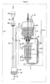
- Figure 1 is a schematic view of one embodiment of the invention showing a dual reaction zone system and an optional assembly for treating impurity gas with a fluorine gas treating assembly.
- a nitrogen trifluoride production system 2 having a first reaction zone 4 and a second reaction zone 6.
- the first reaction zone 4 is typically in the form of one or more conduits or channels having a relatively high aspect ratio typically within the range of from about 5 to 150, preferably from about 10 to 100.
- the second reaction zone typically has a low aspect ratio of up to 5, typically about 1.
- the first reaction zone 4 has a relatively low power input of typically less than about 1000 Watts per cubic meter NH 4 F(HF) x , preferably less than 500 watts/m 3 and makes use of a static mixing of the reactants through the use of static mixing elements which are identified by the numeral 14 and include static mixing elements in the conduit 40.
- the NH 4 F(HF) x flow flux in the first reaction zone 4 is typically in the range of from 30 to 300 cm 3 /cm 2 /second, preferably from 50 to 200 cm 3 /cm 2 /second.
- the dynamic mixer assembly 8 functions include decreasing the gas bubble size in the first reaction zone 4 product stream 10, recycling a portion of the first reaction zone 4 product stream 10 to the first reaction zone via stream 38, transferring a portion of the first reaction zone 4 product stream 10 to the mix tank of the second reaction zone to recover the nitrogen trifluoride product, and transferring a portion of the NH 4 F(HF) x melt from the second reaction zone mix tank with a lower NH 4 F(HF) x melt x value and lower gas concentration to first reaction zone 4 via stream 38. All of these functions can be performed by the impeller contained within the dynamic mixing assembly 8. Additional impellers 12 can be used to increase mixing within the second reaction zone mix tank.
- the dynamic mixing assembly 8 also provides a lesser quantity of energy input to the static mixer elements 14 in the first reaction zone 4.
- the second reaction zone 6 is preferably in the form of a closed, upright cylindrical tank which in addition to the dynamic mixer assembly 8 includes a feed stream 10 from the first reaction zone 4.
- the second reaction zone 6 also includes a crude nitrogen trifluoride gas product outlet 16 through which the crude nitrogen trifluoride gas product obtained from the second reaction zone 6 is optimally sent for further treatment.
- the outlet 16 enables aerated ammonium acid fluoride melt by-product to travel through a conduit 18 to an optional vessel 20 preferably fitted with a heating jacket 22 for assisting in the separation of the NH 4 F(HF) x by-product from the crude NF 3 product 26.
- a substantial portion of the entrained NH 4 F(HF) x crude nitrogen trifluoride product 26 can be advantageously removed using a conventional demister 28 to produce a substantially ammonium acid fluoride free crude nitrogen trifluoride product 30.
- the second reaction zone 6 also includes an inlet 32 in the form of a conduit for transporting the starting material ammonia to the second reaction zone 6 from a source (not shown).
- Fluorine gas is provided to the nitrogen trifluoride production system 2 from a source (not shown) via a conduit 34 into a gas sparger 36.
- the ammonium acid fluoride velocity is sufficient to ensure that essentially all of the fluorine gas exits the first reaction zone 4 via feed stream 10.
- the second reaction zone 6 is provided with an outlet 38 to enable recyclable ammonium acid fluoride to leave the second reaction zone 6 and recirculate into the first reaction zone 4 and eventually back to the second reaction zone 6 via feed stream 10.
- the pathway for the travel of the recycled ammonium acid fluoride is through a conduit 40 having one or more cooling jackets 42 with cooling fluid inlet 44 and outlet 46 to remove the large heat of reaction and control the reactor temperature.
- Both the first and second reaction zone temperatures are typically operated between 110 and 150°C, more preferably between 120 and 140°C.
- the nitrogen trifluoride production system 2 can operate over a variety of conditions providing that the first reaction zone 4 is operated in a relatively low energy environment while the second reaction zone 6 is operated in a relatively high energy environment and therefore provides operating conditions most conducive to the production of NF 3 without excessive corrosion.
- the conversion of fluorine gas to the first reaction product is at least 45%, most preferably at least 65%.
- the reaction of fluorine gas in the first reaction zone 4 reduces the concentration of fluorine gas in the second reaction zone 6 to enable the use of a higher energy environment therein including, for example, low aspect ratios for the reaction zone and a relatively high power input sufficient to operate the mixing assembly without undue corrosion.
- liquid NH 4 F(HF) x melt acidity x value in the range of from about 1.2-2.2, preferably from about 1.4-2.0 and most preferably at a volume ratio of 1.6-1.8, equivalent to ammonium acid fluoride hydrogen fluoride to ammonia ratio ranges of 2.2-3.2:1, 2.4-3.0:1 and 2.6-2.8:1, respectively.
- the crude nitrogen trifluoride product obtained from the outlet 16 will typically be under pressure at about 0.5 to 5 bar absolute, preferably 0.75 to 3 bar absolute and most preferably from about 1 to 2 bar absolute.
- the invention as described above has several advantages over the prior art.
- the present invention avoids the accelerated corrosion associated by the combination of high fluorine concentrations and high sheer rates which is typical of prior art processes. Because the fluorine feed is first contacted with the liquid ammonium acid fluoride in a first reaction zone having a relatively low energy environment (e.g. low power input and high aspect ratio), corrosion in the first reaction zone is essentially avoided while a significant amount of fluorine is converted to the desired nitrogen trifluoride product (i.e. conversion rates typically greater than 35%).
- the second reaction zone can be used to maintain conversion of the fluorine gas despite the declining fluorine partial pressure without excessive corrosion rates.
- a substantial portion of bubbles containing fluorine gas and nitrogen trifluoride gas that are entrained by the dynamic mixing assembly 8 in the second reaction zone 6 can be advantageously recycled to the first reaction zone 4 to substantially increase the gas residence time without having to substantially modify the impeller such as by increasing its length.
- the crude nitrogen trifluoride gas obtained from outlet 30 may be further treated to remove an impurity gas therefrom typically comprising N 2 F 4 and NH 4 F(HF) x melt alone or in combination with N 2 F 2 .
- the impurity gas from the outlet 30 is reacted with fluorine gas in a vessel 48 equipped with metal packing, preferably nickel packing.
- the reaction temperature will typically be in a range of from 200 to 400°C with a gas residence time of about one second.
Landscapes
- Chemical & Material Sciences (AREA)
- Organic Chemistry (AREA)
- Chemical Kinetics & Catalysis (AREA)
- Inorganic Chemistry (AREA)
- Organic Low-Molecular-Weight Compounds And Preparation Thereof (AREA)
- Physical Or Chemical Processes And Apparatus (AREA)
Abstract
Description
- The present invention relates generally to nitrogen trifluoride and more particularly to a reactor system and a method for the production of nitrogen trifluoride from ammonia, elemental fluorine, and liquid ammonium acid fluoride.
- Nitrogen trifluoride (NF3) has been employed for such products as high energy liquid and solid propellants and as a fluorine source for the production of semiconductor devices. Nitrogen fluoride can be prepared by a variety of processes such as disclosed in U.S. Patent Nos. 4,091,081 and 5,637,285 and U.S. Patent Publication No. 2002/0127167 each of which is incorporated herein by reference. The production of nitrogen trifluoride generally results from a series of reactions as described below in which ammonia and fluorine gas are combined with a liquid ammonium acid fluoride intermediate.
- Reaction 1 represents the desired NF3 production reaction.
Reaction 2 is the most rapid undesirable side reaction. Reaction 3 represents the fluorine gas that does not react.

Reaction 2, Reaction 3 are the only fluorine consuming reactions (c1 + c2 + c3=1) and neglects slower, but important, fluorine reactions that produce N2F2 and N2F4, OF2, and other impurities. The c1 and c2 values are the estimated fractions of the fluorine feed that react to produce respectively, the desired NF3 product and the undesirable N2 by-product. The c3 fraction represents the fluorine gas that does not react. The NH4F(HF)x melt acidity x value is the molar ratio of hydrogen fluoride to ammonia minus one in the melt. The α value is the ratio of the actual liquid ammonia acid fluoride melt [NH4F(HF)x] feed rate to the minimum stoichiometric NH4F(HF)x feed rate. The temperature of the reaction zone is moderated by using excess NH4F(HF)x. This simplified process representation neglects other factors, e.g. the small fraction of HF in the crude NF3 vapor product. Despite these limitations Reaction 1,Reaction 2, Reaction 3 provide a good framework to describe the state of the art for NF3 production and the problems associated therewith as discussed below. - Efforts have been made to increase the conversion of F2 to NF3. United States Patent No. 4,091,081 discloses the production of NF3 by sparging fluorine and ammonia into liquid ammonium acid fluoride in a column. United States Patent No. 5,637,285 discloses that simultaneously increasing the hydrogen fluoride content of the ammonium acid fluoride melt and increasing the mixing intensity increases the F2-to-NF3 conversion rate. In particular, increasing the NH4F(HF)x melt acidity "x" value decreases the rate of
Reaction 2 relative to Reaction 1 which tends to increase the overall NF3 yield. However, higher NH4F(HF)x melt acidity "x" values also somewhat decrease the rate of NF3 production via Reaction 1 for a given interfacial surface area. - Although United States Patent 5,637,285 achieves improvements in NF3 yield, some significant problems remain. First, the highly exothermic NF3 reaction is most rapid at the impeller tip, which causes localized overheating, accelerated corrosion at the impeller tip, and mechanical reliability problems. Second, one can not increase the solution depth, to increase the gas residence time, without increasing the mixing shaft length, which also increases mechanical reliability problems.
- United States Patent Application Publication No. US/2002/0127167 A1 employs the advantages of higher mixing intensity as disclosed in United States Patent No. 5,637,285 and higher circulation rate to increase the effective α value to decrease localized overheating, increase F2-to-NF3 conversion (c1), and decrease the impeller corrosion. However, this approach does not address the issue concerning the impeller shaft length or the combination of high mixing rates and high fluorine concentration. In addition, the NH4F(HF)x melt recirculation rate is limited by gaseous product flow rate and gas-liquid separation.
- It would therefore be a significant advantage in the art to provide a NF3 production system with improved yields without the problems associated with corrosion of the mixing assembly (e.g. impeller) due to the corrosive nature of the fluorine gas reactant and high shear rates.
- The present invention is generally directed to the production of NF3 by reacting fluorine gas, ammonia gas and liquid ammonium acid fluoride. The present invention provides a process in which low energy input is provided in vicinity of relatively high concentration of the corrosive reactant fluorine gas and higher energy input is provided in vicinity of relatively low concentrations of fluorine. As a consequence of the present invention, a NF3 producing system is provided with improved yields of NF3 without excessive corrosion of the mixing assembly. The balancing of energy input and fluorine concentration creates a reaction environment that is less conducive to corrosion. In particular, the aspect ratio of the reaction zones and the power input supplied to the reaction zones are selected to construct reaction zones in which conditions which tend to cause corrosion (e.g. high shear rates, high energy input, and high concentration of fluorine gas) are balanced with conditions that tend to favor low corrosion (low shear rates, low energy input, and low concentrations of fluorine gas).
- The process is conducted in two reaction zones in which the first reaction zone is characterized by a relatively high aspect ratio and low power input and is the zone used to react fluorine gas at relatively high concentrations. The second reaction zone enables the process to proceed with a relatively low aspect ratio and high power input where the concentration of fluorine gas is relatively low because some of the fluorine gas has already reacted.
- In a particular aspect of the present invention, there is provided:
- A process for the production of NF3 comprising:
- a) reacting fluorine gas at an initial concentration and liquid ammonium acid fluoride in a first reaction zone in a relatively low energy environment to produce a first reaction product including NF3 and at least some unreacted fluorine gas; and
- b) reacting the first reaction product including the unreacted fluorine gas in a second reaction zone in a relatively high energy environment to produce a second reaction product, wherein the low energy environment in the first reaction zone and the high energy environment in the second reaction zone substantially convert the fluorine gas to NF3 in a manner which at least substantially decreases corrosion in the first and second reaction zones due to the corrosive properties of the fluorine gas.
-
- In a preferred embodiment of the present invention, an impurity gas formed as part of the process of producing NF3 which contains at least the impurities N2F4 and NH4(HF)x are reacted with fluorine gas at elevated temperatures to convert at least some of the impurity to NF3 and essentially completely removing the impurity.
- The present invention is directed to a process for producing NF3 from a reaction mixture containing fluorine gas and liquid ammonium acid fluoride. As will be described below, the reaction is conducted in two reaction zones characterized as having different energy environments. The energy environment in the first reaction zone where the concentration of fluorine gas is relatively high is characterized as being a relatively low energy environment. The energy environment in the second reaction zone where the concentration of fluorine gas is less than the first reaction zone (i.e. because at least in part some of the fluorine gas has reacted in the first reaction zone) is characterized as being a relatively high energy environment.
- The term "relatively high energy environment" shall mean a reaction zone in which reaction conditions and/or features of the reaction zone are selected to provide more energy at the location of the fluorine gas reactant than would appear in a relatively low energy environment. Exemplary reaction conditions and/or structural conditions include, but are not limited to, the power input provided to the reaction zone and the aspect ratio of the reaction zone. Generally, higher power inputs and lower aspect ratios favor high energy environments while lower power inputs and higher aspect ratios favor low energy environments.
- In a particular aspect of the present invention, the two reaction zones are characterized as having different aspect ratios with different power inputs. In the initial low energy environment of the first reaction zone, the aspect ratio is relatively high while mixing is conducted at a relatively low energy input such as the pressure which is applied to the fluorine gas feed to mix the fluorine gas with the other reactants in the presence of static structured mixing assemblies in which mixing is accomplished in the absence of moving parts. In the high energy input reaction environment of the second reaction zone, the aspect ratio of the reaction zone is reduced and the power input is increased so that a mixing assembly typically including an impeller may be used to mix the reactants. The effect of the present process is to overcome difficulties in obtaining effective yields of the desired product (NF3) from a reaction which is characteristically highly exothermic, involves corrosive reactants and typically employs a mixing assembly generating high shear. In particular, the reaction of the fluorine gas with liquid ammonium acid fluoride melt and ammonia gas with the liquid ammonium acid fluoride is conducted in a system that is designed to minimize reaction between gaseous ammonia and fluorine and contains a mixing assembly typically including an impeller. The high heat, corrosive reactants and high shear rates generated from the reaction typically damages any protective layers (e.g. fluoride layers) on the impeller. The combination of high heat, corrosive reactants and high shear rates associated with the process assembly rapidly corrodes the impeller causing shut down of the process assembly and lost production time to replace the impeller.
- The present invention addresses the issue of impeller damage by conducting the process under conditions and in a manner which reduces and/or eliminates impeller damage.
- As used herein the term "aspect ratio" refers to the ratio of the length of a reaction zone to the width of the reaction zone. Thus, for example, a reaction zone comprised of a cylindrical vessel having an aspect ratio of 2 will have a length twice as large as the width. Conversely, an aspect ratio of 0.5 refers to a reaction zone having a length which is one half the width. For a reaction zone composed of a conduit or channel or assembly of channels, the reaction zone aspect ratio is defined as the ratio of channel length to the channel hydraulic diameter. The hydraulic diameter for a channel or assembly of channels is defined as four times the channel cross sectional area divided by channel wall area per unit length.
- The term "power input" refers to the mechanical energy input to either reaction zone, but not energy transferred between the reaction zones. Typically, a mixer, pump, or compressed gas is used to input power to either reaction zone. The power input is measured in terms of Watts per cubic meter of the total NH4F(HF)x melt volume in the first and second reaction zones. In accordance with a particular aspect of the present invention, two reaction zones are provided, the first having a relatively high aspect ratio (i.e. the length of the reaction zone exceeds the width) and low power input (e.g. moderate pressure fluorine feed). A second reaction zone is provided which is essentially the converse of the first reaction zone in that the second reaction zone will have a relatively low aspect ratio and a relatively high power input.
- The following drawing is illustrative of an embodiment of the invention and is not intended to limit the invention as encompassed by the claims forming part of the application.
- Figure 1 is a schematic view of one embodiment of the invention showing a dual reaction zone system and an optional assembly for treating impurity gas with a fluorine gas treating assembly.
- Referring to Figure 1, there is shown a nitrogen
trifluoride production system 2 having afirst reaction zone 4 and a second reaction zone 6. Thefirst reaction zone 4 is typically in the form of one or more conduits or channels having a relatively high aspect ratio typically within the range of from about 5 to 150, preferably from about 10 to 100. The second reaction zone typically has a low aspect ratio of up to 5, typically about 1. Thefirst reaction zone 4 has a relatively low power input of typically less than about 1000 Watts per cubic meter NH4F(HF)x, preferably less than 500 watts/m3 and makes use of a static mixing of the reactants through the use of static mixing elements which are identified by the numeral 14 and include static mixing elements in theconduit 40. Static mixing elements including heat exchange capability are available under the trademark Kenics from Chemineer, Inc. The NH4F(HF)x flow flux in thefirst reaction zone 4 is typically in the range of from 30 to 300 cm3/cm2/second, preferably from 50 to 200 cm3/cm2/second. - More power is inputted into the second reaction zone 6 and is sufficient to operate a dynamic mixer assembly 8. The dynamic mixer assembly 8 functions include decreasing the gas bubble size in the
first reaction zone 4product stream 10, recycling a portion of thefirst reaction zone 4product stream 10 to the first reaction zone viastream 38, transferring a portion of thefirst reaction zone 4product stream 10 to the mix tank of the second reaction zone to recover the nitrogen trifluoride product, and transferring a portion of the NH4F(HF)x melt from the second reaction zone mix tank with a lower NH4F(HF)x melt x value and lower gas concentration tofirst reaction zone 4 viastream 38. All of these functions can be performed by the impeller contained within the dynamic mixing assembly 8. Additional impellers 12 can be used to increase mixing within the second reaction zone mix tank. The dynamic mixing assembly 8 also provides a lesser quantity of energy input to thestatic mixer elements 14 in thefirst reaction zone 4. - The second reaction zone 6 is preferably in the form of a closed, upright cylindrical tank which in addition to the dynamic mixer assembly 8 includes a
feed stream 10 from thefirst reaction zone 4. - The second reaction zone 6 also includes a crude nitrogen trifluoride
gas product outlet 16 through which the crude nitrogen trifluoride gas product obtained from the second reaction zone 6 is optimally sent for further treatment. - The
outlet 16 enables aerated ammonium acid fluoride melt by-product to travel through aconduit 18 to anoptional vessel 20 preferably fitted with aheating jacket 22 for assisting in the separation of the NH4F(HF)x by-product from the crude NF3 product 26. A substantial portion of the entrained NH4F(HF)x crudenitrogen trifluoride product 26 can be advantageously removed using aconventional demister 28 to produce a substantially ammonium acid fluoride free crudenitrogen trifluoride product 30. - The second reaction zone 6 also includes an
inlet 32 in the form of a conduit for transporting the starting material ammonia to the second reaction zone 6 from a source (not shown). Fluorine gas is provided to the nitrogentrifluoride production system 2 from a source (not shown) via aconduit 34 into agas sparger 36. At the point the fluorine gas enters thefirst reaction zone 4, the ammonium acid fluoride velocity is sufficient to ensure that essentially all of the fluorine gas exits thefirst reaction zone 4 viafeed stream 10. - The second reaction zone 6 is provided with an
outlet 38 to enable recyclable ammonium acid fluoride to leave the second reaction zone 6 and recirculate into thefirst reaction zone 4 and eventually back to the second reaction zone 6 viafeed stream 10. The pathway for the travel of the recycled ammonium acid fluoride is through aconduit 40 having one ormore cooling jackets 42 with coolingfluid inlet 44 and outlet 46 to remove the large heat of reaction and control the reactor temperature. Both the first and second reaction zone temperatures are typically operated between 110 and 150°C, more preferably between 120 and 140°C. - The nitrogen
trifluoride production system 2 can operate over a variety of conditions providing that thefirst reaction zone 4 is operated in a relatively low energy environment while the second reaction zone 6 is operated in a relatively high energy environment and therefore provides operating conditions most conducive to the production of NF3 without excessive corrosion. In carrying out the production of nitrogen trifluoride, it is desirable that in thefirst reaction zone 4, at least 35% of the fluorine gas is converted to a first reaction product containing nitrogen trifluoride. Preferably, the conversion of fluorine gas to the first reaction product is at least 45%, most preferably at least 65%. The reaction of fluorine gas in thefirst reaction zone 4 reduces the concentration of fluorine gas in the second reaction zone 6 to enable the use of a higher energy environment therein including, for example, low aspect ratios for the reaction zone and a relatively high power input sufficient to operate the mixing assembly without undue corrosion. - It is desirable to employ a liquid NH4F(HF)x melt acidity x value in the range of from about 1.2-2.2, preferably from about 1.4-2.0 and most preferably at a volume ratio of 1.6-1.8, equivalent to ammonium acid fluoride hydrogen fluoride to ammonia ratio ranges of 2.2-3.2:1, 2.4-3.0:1 and 2.6-2.8:1, respectively.
- The crude nitrogen trifluoride product obtained from the
outlet 16 will typically be under pressure at about 0.5 to 5 bar absolute, preferably 0.75 to 3 bar absolute and most preferably from about 1 to 2 bar absolute. - The invention as described above has several advantages over the prior art. The present invention avoids the accelerated corrosion associated by the combination of high fluorine concentrations and high sheer rates which is typical of prior art processes. Because the fluorine feed is first contacted with the liquid ammonium acid fluoride in a first reaction zone having a relatively low energy environment (e.g. low power input and high aspect ratio), corrosion in the first reaction zone is essentially avoided while a significant amount of fluorine is converted to the desired nitrogen trifluoride product (i.e. conversion rates typically greater than 35%). The second reaction zone can be used to maintain conversion of the fluorine gas despite the declining fluorine partial pressure without excessive corrosion rates. A substantial portion of bubbles containing fluorine gas and nitrogen trifluoride gas that are entrained by the dynamic mixing assembly 8 in the second reaction zone 6 can be advantageously recycled to the
first reaction zone 4 to substantially increase the gas residence time without having to substantially modify the impeller such as by increasing its length. - In a further aspect of the present invention, the crude nitrogen trifluoride gas obtained from
outlet 30 may be further treated to remove an impurity gas therefrom typically comprising N2F4 and NH4F(HF)x melt alone or in combination with N2F2. The impurity gas from theoutlet 30 is reacted with fluorine gas in avessel 48 equipped with metal packing, preferably nickel packing. The reaction temperature will typically be in a range of from 200 to 400°C with a gas residence time of about one second. These operating conditions remove essentially all the subfluorinated impurities [N2F4, N2F2, and NH4F(HF)x] and produce some nitrogen trifluoride. - The foregoing embodiments are illustrative of the invention and modifications and expansions of the invention within the routine skill of the art are encompassed by the present application.
Claims (25)
- A process for the production of NF3 comprising:a) reacting fluorine gas at an initial concentration and liquid ammonium acid fluoride in a first reaction zone in a relatively low energy environment to produce a first reaction product including NF3 and at least some unreacted fluorine gas; andb) reacting the first reaction product including the unreacted fluorine gas in a second reaction zone in a relatively high energy environment to produce a second reaction product, wherein the low energy environment in the first reaction zone and the high energy environment in the second reaction zone substantially convert the fluorine gas to NF3 in a manner which at least substantially reduces corrosion in the first and second reaction zones due to the corrosive properties of the fluorine gas.
- The process of claim 1 further comprising separating the NF3 from the second reaction product.
- The process of claim 1 or claim 2 wherein the first reaction zone has a first power input and a first aspect ratio and the second reaction zone has a second power input higher than the first power input and a second aspect ratio lower than the first aspect ratio.
- The process of claim 3 wherein the first aspect ratio is from about 5 to 150.
- The process of claim 4 wherein the first aspect ratio is from about 10 to 100.
- The process of any of claims 3 to 5 wherein the first power input in the reaction zone is less than about 1,000 watts/per cubic meter of NH4F(HF)x.
- The process of claim 6 wherein the first power input in the first reaction zone is less than about 500 watts per cubic meter of NH4F(HF)x.
- The process of any of claims 3 to 7 wherein the second aspect ratio is up to about 5
- The process of claim 8 wherein the second aspect ratio is about 1.
- The process of any of claims 3 to 9 wherein the second power input in the second reaction zone is at least 5,000 watts per cubic meter of NH4F(HF)x.
- The process of any preceding claim wherein the reaction of fluorine gas in the first reaction zone converts at least 35% of the fluorine gas to the first reaction product.
- The process of claim 11 wherein the reaction of fluorine gas in the first reaction zone converts at least 45% of the fluorine gas to the first reaction product.
- The process of claim 12 wherein the reaction of fluorine gas in the first reaction zone converts at least 65% of the fluorine gas to the first reaction product.
- The process of any preceding claim wherein the first power input in the first reaction zone is in part obtained from the introduction of the fluorine gas to the first reaction zone.
- The process of any preceding claim comprising conducting the reaction in the first and second reaction zones at a temperature of from about 110 to 150°C.
- The process of claim 15 comprising conducting the reaction in the first and second reaction zones at a temperature of from about 120 to 140°C.
- The process of any preceding claim wherein the liquid NH4F(HF)x melt acidity x value is from about 1.2-2.2.
- The process of claim 17 wherein the melt acidity x value is from about 1.4-2.0.
- The process of claim 18 wherein the melt acidity x value is from about 1.6-1.8.
- The process of any preceding claim wherein the first reaction product contains an impurity gas comprising N2F4, said process further comprising reacting the impurity gas with fluorine gas at an elevated temperature to convert at least some of the impurity gas to NF3.
- The process of claim 20 wherein the impurity gas comprises N2F4 and N2F2.
- The process of claim 20 or 21 comprising reacting the impurity gas with fluorine gas at a temperature of 200 to 400°C.
- The process of any preceding claim wherein the first reaction zone includes a static mixing element.
- The process of any preceding claim wherein the second reaction zone includes a dynamic mixing assembly.
- Apparatus for the production of NF3 comprising:a) a first reaction zone for reacting fluorine gas at an initial concentration and liquid ammonium acid fluoride;b) means for providing a low energy environment to the first reaction zone to produce a first reaction product including NF3 and at least some unreacted fluorine gas;c) a second reaction zone for receiving the first reaction product and for reacting the unreacted fluorine gas therein; andd) means for providing a high energy environment to the second reaction zone to convert the fluorine gas to NF3 in a manner which substantially reduces corrosion in the first and second reaction zones due to the corrosive properties of the fluorine gas.
Applications Claiming Priority (4)
| Application Number | Priority Date | Filing Date | Title |
|---|---|---|---|
| US43607002P | 2002-12-23 | 2002-12-23 | |
| US436070P | 2002-12-23 | ||
| US10/735,158 US7128885B2 (en) | 2002-12-23 | 2003-12-12 | NF3 production reactor |
| US735158 | 2003-12-12 |
Publications (2)
| Publication Number | Publication Date |
|---|---|
| EP1433748A2 true EP1433748A2 (en) | 2004-06-30 |
| EP1433748A3 EP1433748A3 (en) | 2006-08-16 |
Family
ID=32474671
Family Applications (1)
| Application Number | Title | Priority Date | Filing Date |
|---|---|---|---|
| EP03258137A Withdrawn EP1433748A3 (en) | 2002-12-23 | 2003-12-22 | Process and production reactor for the preparation of nitrogen trifluoride |
Country Status (7)
| Country | Link |
|---|---|
| US (1) | US7128885B2 (en) |
| EP (1) | EP1433748A3 (en) |
| JP (1) | JP4536368B2 (en) |
| KR (1) | KR101027256B1 (en) |
| CN (1) | CN1312029C (en) |
| SG (1) | SG114647A1 (en) |
| TW (1) | TWI325846B (en) |
Cited By (4)
| Publication number | Priority date | Publication date | Assignee | Title |
|---|---|---|---|---|
| EP2246296A1 (en) * | 2007-12-27 | 2010-11-03 | Central Glass Co., Ltd. | Process and apparatus for producing fluorinated gaseous compound |
| ITMI20091797A1 (en) * | 2009-10-19 | 2011-04-20 | Giordano Colombo | REACTION EQUIPMENT AND EMULSIFICATION, PARTICULARLY FOR EMULSIFYING WATER AND DIESEL FUEL AND THE EMULSIFICATION METHOD USING THIS EQUIPMENT |
| US11015126B2 (en) | 2016-12-30 | 2021-05-25 | Eme International Limited | Apparatus and method for producing biomass derived liquid, bio-fuel and bio-material |
| US11084004B2 (en) | 2014-11-10 | 2021-08-10 | Eme International Lux S.A. | Device for mixing water and diesel oil, apparatus and process for producing a water/diesel oil micro-emulsion |
Families Citing this family (8)
| Publication number | Priority date | Publication date | Assignee | Title |
|---|---|---|---|---|
| KR100452233B1 (en) * | 2002-07-19 | 2004-10-12 | 한국과학기술연구원 | production method of trifluoronitrogen using jet-loop reactors |
| US7395823B2 (en) * | 2004-04-09 | 2008-07-08 | The Boc Group, Inc. | Method and apparatus for local fluorine and nitrogen trifluoride production |
| US7045107B2 (en) * | 2004-09-20 | 2006-05-16 | Air Products And Chemicals, Inc. | Process for the production of nitrogen trifluoride |
| CN1328159C (en) * | 2005-07-27 | 2007-07-25 | 中国船舶重工集团公司第七一八研究所 | Equipment and technological process for preparing nitrogen trifluoride by using ammonia and hydrogen fluoride as raw material |
| US7413722B2 (en) * | 2005-08-04 | 2008-08-19 | Foosung Co., Ltd. | Method and apparatus for manufacturing nitrogen trifluoride |
| US20090038701A1 (en) | 2006-01-17 | 2009-02-12 | Baxter International Inc. | Device, system and method for mixing |
| US8163262B1 (en) | 2011-01-04 | 2012-04-24 | Omotowa Bamidele A | Method for production of nitrogen trifluoride from trimethylsilylamines |
| RU2497567C1 (en) * | 2012-06-06 | 2013-11-10 | ОТКРЫТОЕ АКЦИОНЕРНОЕ ОБЩЕСТВО "СИБУР Холдинг" | Gas-fluid reactor |
Citations (3)
| Publication number | Priority date | Publication date | Assignee | Title |
|---|---|---|---|---|
| US4091081A (en) * | 1977-04-19 | 1978-05-23 | Air Products And Chemicals, Inc. | Preparation of nitrogen trifluoride |
| US5637285A (en) * | 1996-01-30 | 1997-06-10 | Air Products And Chemicals, Inc. | Process for nitrogen trifluoride synthesis |
| WO2002092504A1 (en) * | 2001-05-11 | 2002-11-21 | Obschestvo S Ogranichennoi Otvetstvennostiu 'neuchem' | Method for producing nitrogen fluoride |
Family Cites Families (10)
| Publication number | Priority date | Publication date | Assignee | Title |
|---|---|---|---|---|
| JPS6071503A (en) * | 1983-09-27 | 1985-04-23 | Central Glass Co Ltd | Manufacture of nf3 |
| US4661318A (en) * | 1984-03-28 | 1987-04-28 | Phillips Petroleum Company | Apparatus for continuous overbasing of petroleum sulfonate with water removal and methanol addition between reaction stages |
| JP2930351B2 (en) * | 1990-02-06 | 1999-08-03 | 関東電化工業株式会社 | Manufacturing method of NF (3) |
| JP3727797B2 (en) * | 1998-05-22 | 2005-12-14 | セントラル硝子株式会社 | Method for producing nitrogen trifluoride |
| WO2001085603A2 (en) * | 2000-05-12 | 2001-11-15 | Showa Denko K. K. | Process for producing nitrogen trifluoride and use thereof |
| US6986874B2 (en) | 2000-12-14 | 2006-01-17 | The Boc Group, Inc. | Method and apparatus for the production of nitrogen trifluoride |
| US6908601B2 (en) * | 2002-02-08 | 2005-06-21 | The Boc Group, Inc. | Method for the production of nitrogen trifluoride |
| US6790428B2 (en) * | 2002-03-20 | 2004-09-14 | Air Products And Chemicals, Inc. | Process for the reduction or elimination of NH3/HF byproduct in the manufacture of nitrogen trifluoride |
| KR100452233B1 (en) * | 2002-07-19 | 2004-10-12 | 한국과학기술연구원 | production method of trifluoronitrogen using jet-loop reactors |
| US20040096386A1 (en) * | 2002-11-19 | 2004-05-20 | Syvret Robert George | Method for nitrogen trifluoride production |
-
2003
- 2003-12-12 US US10/735,158 patent/US7128885B2/en not_active Expired - Fee Related
- 2003-12-22 EP EP03258137A patent/EP1433748A3/en not_active Withdrawn
- 2003-12-23 SG SG200307841A patent/SG114647A1/en unknown
- 2003-12-23 KR KR1020030095519A patent/KR101027256B1/en not_active IP Right Cessation
- 2003-12-23 TW TW092136569A patent/TWI325846B/en not_active IP Right Cessation
- 2003-12-23 CN CNB2003101177941A patent/CN1312029C/en not_active Expired - Fee Related
- 2003-12-24 JP JP2003426959A patent/JP4536368B2/en not_active Expired - Fee Related
Patent Citations (3)
| Publication number | Priority date | Publication date | Assignee | Title |
|---|---|---|---|---|
| US4091081A (en) * | 1977-04-19 | 1978-05-23 | Air Products And Chemicals, Inc. | Preparation of nitrogen trifluoride |
| US5637285A (en) * | 1996-01-30 | 1997-06-10 | Air Products And Chemicals, Inc. | Process for nitrogen trifluoride synthesis |
| WO2002092504A1 (en) * | 2001-05-11 | 2002-11-21 | Obschestvo S Ogranichennoi Otvetstvennostiu 'neuchem' | Method for producing nitrogen fluoride |
Cited By (6)
| Publication number | Priority date | Publication date | Assignee | Title |
|---|---|---|---|---|
| EP2246296A1 (en) * | 2007-12-27 | 2010-11-03 | Central Glass Co., Ltd. | Process and apparatus for producing fluorinated gaseous compound |
| EP2246296A4 (en) * | 2007-12-27 | 2011-08-31 | Central Glass Co Ltd | Process and apparatus for producing fluorinated gaseous compound |
| CN101896423B (en) * | 2007-12-27 | 2012-10-10 | 中央硝子株式会社 | Process and apparatus for producing fluorinated gaseous compound |
| ITMI20091797A1 (en) * | 2009-10-19 | 2011-04-20 | Giordano Colombo | REACTION EQUIPMENT AND EMULSIFICATION, PARTICULARLY FOR EMULSIFYING WATER AND DIESEL FUEL AND THE EMULSIFICATION METHOD USING THIS EQUIPMENT |
| US11084004B2 (en) | 2014-11-10 | 2021-08-10 | Eme International Lux S.A. | Device for mixing water and diesel oil, apparatus and process for producing a water/diesel oil micro-emulsion |
| US11015126B2 (en) | 2016-12-30 | 2021-05-25 | Eme International Limited | Apparatus and method for producing biomass derived liquid, bio-fuel and bio-material |
Also Published As
| Publication number | Publication date |
|---|---|
| TWI325846B (en) | 2010-06-11 |
| CN1535916A (en) | 2004-10-13 |
| JP4536368B2 (en) | 2010-09-01 |
| KR101027256B1 (en) | 2011-04-06 |
| JP2004203739A (en) | 2004-07-22 |
| TW200427625A (en) | 2004-12-16 |
| US7128885B2 (en) | 2006-10-31 |
| EP1433748A3 (en) | 2006-08-16 |
| CN1312029C (en) | 2007-04-25 |
| KR20040058047A (en) | 2004-07-03 |
| US20040120877A1 (en) | 2004-06-24 |
| SG114647A1 (en) | 2005-09-28 |
Similar Documents
| Publication | Publication Date | Title |
|---|---|---|
| US7128885B2 (en) | NF3 production reactor | |
| EP3782972A1 (en) | Process for preparing fluorobenzene by direct fluorination | |
| US6908601B2 (en) | Method for the production of nitrogen trifluoride | |
| EP0787684B1 (en) | Process for nitrogen trifluoride synthesis | |
| EP0155735B1 (en) | Process for the preparation of urea | |
| EP0384565B1 (en) | Treatment of nitrogen oxides | |
| US7144568B2 (en) | Method and device for carrying out a reaction in liquid medium with gas evolution | |
| US6986874B2 (en) | Method and apparatus for the production of nitrogen trifluoride | |
| US5439663A (en) | Method for producing Caro's acid | |
| EP0514848A2 (en) | Process and apparatus for the generation of peroxyacids | |
| JP5602143B2 (en) | A method for reducing the formation of by-product dinitrobenzene in the production of mononitrobenzene | |
| CN108513573A (en) | The manufacturing method and manufacturing device of alkyl nitrite | |
| US4334096A (en) | Process for synthesizing urea | |
| US7413722B2 (en) | Method and apparatus for manufacturing nitrogen trifluoride | |
| US5470564A (en) | Method for producing caro's acid | |
| US11261144B2 (en) | Process for preparing fluorobenzene by direct fluorination | |
| RU2136590C1 (en) | Polycrystalline silicon production process | |
| RU2404118C2 (en) | Chlorine dioxide synthesis method | |
| JP2023108791A (en) | Urea synthesis method | |
| GB2029821A (en) | Process for the preparation of glycerol dichlorohydrins | |
| EP0460075A1 (en) | Preparation of nitrosyl fluoride. | |
| RU2256605C1 (en) | Method for preparing nitrogen trifluoride | |
| JP2003221210A (en) | Method and apparatus for producing heavy nitrogen | |
| KR20040012817A (en) | Method for producing nitrogen fluorides |
Legal Events
| Date | Code | Title | Description |
|---|---|---|---|
| PUAI | Public reference made under article 153(3) epc to a published international application that has entered the european phase |
Free format text: ORIGINAL CODE: 0009012 |
|
| AK | Designated contracting states |
Kind code of ref document: A2 Designated state(s): AT BE BG CH CY CZ DE DK EE ES FI FR GB GR HU IE IT LI LU MC NL PT RO SE SI SK TR |
|
| AX | Request for extension of the european patent |
Extension state: AL LT LV MK |
|
| PUAL | Search report despatched |
Free format text: ORIGINAL CODE: 0009013 |
|
| AK | Designated contracting states |
Kind code of ref document: A3 Designated state(s): AT BE BG CH CY CZ DE DK EE ES FI FR GB GR HU IE IT LI LU MC NL PT RO SE SI SK TR |
|
| AX | Request for extension of the european patent |
Extension state: AL LT LV MK |
|
| RIC1 | Information provided on ipc code assigned before grant |
Ipc: B01F 5/10 20060101ALI20060711BHEP Ipc: B01F 13/10 20060101ALI20060711BHEP Ipc: B01J 19/18 20060101ALI20060711BHEP Ipc: B01J 19/24 20060101ALI20060711BHEP Ipc: B01J 19/00 20060101ALI20060711BHEP Ipc: C01B 21/083 20060101AFI20040423BHEP |
|
| AKX | Designation fees paid | ||
| REG | Reference to a national code |
Ref country code: DE Ref legal event code: 8566 |
|
| STAA | Information on the status of an ep patent application or granted ep patent |
Free format text: STATUS: THE APPLICATION IS DEEMED TO BE WITHDRAWN |
|
| 18D | Application deemed to be withdrawn |
Effective date: 20070217 |