EP1433746A2 - Catalytic partial oxidation method - Google Patents
Catalytic partial oxidation method Download PDFInfo
- Publication number
- EP1433746A2 EP1433746A2 EP03257653A EP03257653A EP1433746A2 EP 1433746 A2 EP1433746 A2 EP 1433746A2 EP 03257653 A EP03257653 A EP 03257653A EP 03257653 A EP03257653 A EP 03257653A EP 1433746 A2 EP1433746 A2 EP 1433746A2
- Authority
- EP
- European Patent Office
- Prior art keywords
- hydrogen
- mixture
- partial oxidation
- catalyst
- feed gas
- Prior art date
- Legal status (The legal status is an assumption and is not a legal conclusion. Google has not performed a legal analysis and makes no representation as to the accuracy of the status listed.)
- Withdrawn
Links
Images


Classifications
-
- C—CHEMISTRY; METALLURGY
- C01—INORGANIC CHEMISTRY
- C01B—NON-METALLIC ELEMENTS; COMPOUNDS THEREOF; METALLOIDS OR COMPOUNDS THEREOF NOT COVERED BY SUBCLASS C01C
- C01B3/00—Hydrogen; Gaseous mixtures containing hydrogen; Separation of hydrogen from mixtures containing it; Purification of hydrogen; Reversible storage of hydrogen
- C01B3/02—Production of hydrogen; Production of gaseous mixtures containing hydrogen
- C01B3/32—Production of hydrogen; Production of gaseous mixtures containing hydrogen by reaction of gaseous or liquid organic compounds with gasifying agents, e.g. water, carbon dioxide or air
- C01B3/34—Production of hydrogen; Production of gaseous mixtures containing hydrogen by reaction of gaseous or liquid organic compounds with gasifying agents, e.g. water, carbon dioxide or air by reaction of hydrocarbons with gasifying agents
- C01B3/38—Production of hydrogen; Production of gaseous mixtures containing hydrogen by reaction of gaseous or liquid organic compounds with gasifying agents, e.g. water, carbon dioxide or air by reaction of hydrocarbons with gasifying agents using catalysts
- C01B3/386—Catalytic partial combustion
-
- C—CHEMISTRY; METALLURGY
- C07—ORGANIC CHEMISTRY
- C07C—ACYCLIC OR CARBOCYCLIC COMPOUNDS
- C07C2/00—Preparation of hydrocarbons from hydrocarbons containing a smaller number of carbon atoms
- C07C2/02—Preparation of hydrocarbons from hydrocarbons containing a smaller number of carbon atoms by addition between unsaturated hydrocarbons
- C07C2/04—Preparation of hydrocarbons from hydrocarbons containing a smaller number of carbon atoms by addition between unsaturated hydrocarbons by oligomerisation of well-defined unsaturated hydrocarbons without ring formation
- C07C2/06—Preparation of hydrocarbons from hydrocarbons containing a smaller number of carbon atoms by addition between unsaturated hydrocarbons by oligomerisation of well-defined unsaturated hydrocarbons without ring formation of alkenes, i.e. acyclic hydrocarbons having only one carbon-to-carbon double bond
- C07C2/08—Catalytic processes
- C07C2/10—Catalytic processes with metal oxides
-
- C—CHEMISTRY; METALLURGY
- C01—INORGANIC CHEMISTRY
- C01B—NON-METALLIC ELEMENTS; COMPOUNDS THEREOF; METALLOIDS OR COMPOUNDS THEREOF NOT COVERED BY SUBCLASS C01C
- C01B2203/00—Integrated processes for the production of hydrogen or synthesis gas
- C01B2203/02—Processes for making hydrogen or synthesis gas
- C01B2203/025—Processes for making hydrogen or synthesis gas containing a partial oxidation step
- C01B2203/0261—Processes for making hydrogen or synthesis gas containing a partial oxidation step containing a catalytic partial oxidation step [CPO]
-
- C—CHEMISTRY; METALLURGY
- C01—INORGANIC CHEMISTRY
- C01B—NON-METALLIC ELEMENTS; COMPOUNDS THEREOF; METALLOIDS OR COMPOUNDS THEREOF NOT COVERED BY SUBCLASS C01C
- C01B2203/00—Integrated processes for the production of hydrogen or synthesis gas
- C01B2203/04—Integrated processes for the production of hydrogen or synthesis gas containing a purification step for the hydrogen or the synthesis gas
- C01B2203/042—Purification by adsorption on solids
- C01B2203/043—Regenerative adsorption process in two or more beds, one for adsorption, the other for regeneration
-
- C—CHEMISTRY; METALLURGY
- C01—INORGANIC CHEMISTRY
- C01B—NON-METALLIC ELEMENTS; COMPOUNDS THEREOF; METALLOIDS OR COMPOUNDS THEREOF NOT COVERED BY SUBCLASS C01C
- C01B2203/00—Integrated processes for the production of hydrogen or synthesis gas
- C01B2203/04—Integrated processes for the production of hydrogen or synthesis gas containing a purification step for the hydrogen or the synthesis gas
- C01B2203/046—Purification by cryogenic separation
-
- C—CHEMISTRY; METALLURGY
- C01—INORGANIC CHEMISTRY
- C01B—NON-METALLIC ELEMENTS; COMPOUNDS THEREOF; METALLOIDS OR COMPOUNDS THEREOF NOT COVERED BY SUBCLASS C01C
- C01B2203/00—Integrated processes for the production of hydrogen or synthesis gas
- C01B2203/04—Integrated processes for the production of hydrogen or synthesis gas containing a purification step for the hydrogen or the synthesis gas
- C01B2203/0465—Composition of the impurity
- C01B2203/047—Composition of the impurity the impurity being carbon monoxide
-
- C—CHEMISTRY; METALLURGY
- C01—INORGANIC CHEMISTRY
- C01B—NON-METALLIC ELEMENTS; COMPOUNDS THEREOF; METALLOIDS OR COMPOUNDS THEREOF NOT COVERED BY SUBCLASS C01C
- C01B2203/00—Integrated processes for the production of hydrogen or synthesis gas
- C01B2203/08—Methods of heating or cooling
- C01B2203/0872—Methods of cooling
- C01B2203/0877—Methods of cooling by direct injection of fluid
-
- C—CHEMISTRY; METALLURGY
- C01—INORGANIC CHEMISTRY
- C01B—NON-METALLIC ELEMENTS; COMPOUNDS THEREOF; METALLOIDS OR COMPOUNDS THEREOF NOT COVERED BY SUBCLASS C01C
- C01B2203/00—Integrated processes for the production of hydrogen or synthesis gas
- C01B2203/10—Catalysts for performing the hydrogen forming reactions
- C01B2203/1005—Arrangement or shape of catalyst
- C01B2203/1023—Catalysts in the form of a monolith or honeycomb
-
- C—CHEMISTRY; METALLURGY
- C01—INORGANIC CHEMISTRY
- C01B—NON-METALLIC ELEMENTS; COMPOUNDS THEREOF; METALLOIDS OR COMPOUNDS THEREOF NOT COVERED BY SUBCLASS C01C
- C01B2203/00—Integrated processes for the production of hydrogen or synthesis gas
- C01B2203/10—Catalysts for performing the hydrogen forming reactions
- C01B2203/1041—Composition of the catalyst
-
- C—CHEMISTRY; METALLURGY
- C01—INORGANIC CHEMISTRY
- C01B—NON-METALLIC ELEMENTS; COMPOUNDS THEREOF; METALLOIDS OR COMPOUNDS THEREOF NOT COVERED BY SUBCLASS C01C
- C01B2203/00—Integrated processes for the production of hydrogen or synthesis gas
- C01B2203/10—Catalysts for performing the hydrogen forming reactions
- C01B2203/1041—Composition of the catalyst
- C01B2203/1047—Group VIII metal catalysts
-
- C—CHEMISTRY; METALLURGY
- C01—INORGANIC CHEMISTRY
- C01B—NON-METALLIC ELEMENTS; COMPOUNDS THEREOF; METALLOIDS OR COMPOUNDS THEREOF NOT COVERED BY SUBCLASS C01C
- C01B2203/00—Integrated processes for the production of hydrogen or synthesis gas
- C01B2203/10—Catalysts for performing the hydrogen forming reactions
- C01B2203/1041—Composition of the catalyst
- C01B2203/1047—Group VIII metal catalysts
- C01B2203/1052—Nickel or cobalt catalysts
-
- C—CHEMISTRY; METALLURGY
- C01—INORGANIC CHEMISTRY
- C01B—NON-METALLIC ELEMENTS; COMPOUNDS THEREOF; METALLOIDS OR COMPOUNDS THEREOF NOT COVERED BY SUBCLASS C01C
- C01B2203/00—Integrated processes for the production of hydrogen or synthesis gas
- C01B2203/10—Catalysts for performing the hydrogen forming reactions
- C01B2203/1041—Composition of the catalyst
- C01B2203/1047—Group VIII metal catalysts
- C01B2203/1064—Platinum group metal catalysts
-
- C—CHEMISTRY; METALLURGY
- C01—INORGANIC CHEMISTRY
- C01B—NON-METALLIC ELEMENTS; COMPOUNDS THEREOF; METALLOIDS OR COMPOUNDS THEREOF NOT COVERED BY SUBCLASS C01C
- C01B2203/00—Integrated processes for the production of hydrogen or synthesis gas
- C01B2203/10—Catalysts for performing the hydrogen forming reactions
- C01B2203/1041—Composition of the catalyst
- C01B2203/1082—Composition of support materials
-
- C—CHEMISTRY; METALLURGY
- C01—INORGANIC CHEMISTRY
- C01B—NON-METALLIC ELEMENTS; COMPOUNDS THEREOF; METALLOIDS OR COMPOUNDS THEREOF NOT COVERED BY SUBCLASS C01C
- C01B2203/00—Integrated processes for the production of hydrogen or synthesis gas
- C01B2203/12—Feeding the process for making hydrogen or synthesis gas
- C01B2203/1205—Composition of the feed
- C01B2203/1211—Organic compounds or organic mixtures used in the process for making hydrogen or synthesis gas
- C01B2203/1235—Hydrocarbons
- C01B2203/1241—Natural gas or methane
-
- C—CHEMISTRY; METALLURGY
- C01—INORGANIC CHEMISTRY
- C01B—NON-METALLIC ELEMENTS; COMPOUNDS THEREOF; METALLOIDS OR COMPOUNDS THEREOF NOT COVERED BY SUBCLASS C01C
- C01B2203/00—Integrated processes for the production of hydrogen or synthesis gas
- C01B2203/12—Feeding the process for making hydrogen or synthesis gas
- C01B2203/1276—Mixing of different feed components
-
- C—CHEMISTRY; METALLURGY
- C01—INORGANIC CHEMISTRY
- C01B—NON-METALLIC ELEMENTS; COMPOUNDS THEREOF; METALLOIDS OR COMPOUNDS THEREOF NOT COVERED BY SUBCLASS C01C
- C01B2203/00—Integrated processes for the production of hydrogen or synthesis gas
- C01B2203/14—Details of the flowsheet
- C01B2203/146—At least two purification steps in series
-
- C—CHEMISTRY; METALLURGY
- C01—INORGANIC CHEMISTRY
- C01B—NON-METALLIC ELEMENTS; COMPOUNDS THEREOF; METALLOIDS OR COMPOUNDS THEREOF NOT COVERED BY SUBCLASS C01C
- C01B2203/00—Integrated processes for the production of hydrogen or synthesis gas
- C01B2203/14—Details of the flowsheet
- C01B2203/148—Details of the flowsheet involving a recycle stream to the feed of the process for making hydrogen or synthesis gas
-
- C—CHEMISTRY; METALLURGY
- C01—INORGANIC CHEMISTRY
- C01B—NON-METALLIC ELEMENTS; COMPOUNDS THEREOF; METALLOIDS OR COMPOUNDS THEREOF NOT COVERED BY SUBCLASS C01C
- C01B2203/00—Integrated processes for the production of hydrogen or synthesis gas
- C01B2203/16—Controlling the process
- C01B2203/1604—Starting up the process
-
- C—CHEMISTRY; METALLURGY
- C01—INORGANIC CHEMISTRY
- C01B—NON-METALLIC ELEMENTS; COMPOUNDS THEREOF; METALLOIDS OR COMPOUNDS THEREOF NOT COVERED BY SUBCLASS C01C
- C01B2203/00—Integrated processes for the production of hydrogen or synthesis gas
- C01B2203/16—Controlling the process
- C01B2203/1609—Shutting down the process
-
- Y—GENERAL TAGGING OF NEW TECHNOLOGICAL DEVELOPMENTS; GENERAL TAGGING OF CROSS-SECTIONAL TECHNOLOGIES SPANNING OVER SEVERAL SECTIONS OF THE IPC; TECHNICAL SUBJECTS COVERED BY FORMER USPC CROSS-REFERENCE ART COLLECTIONS [XRACs] AND DIGESTS
- Y02—TECHNOLOGIES OR APPLICATIONS FOR MITIGATION OR ADAPTATION AGAINST CLIMATE CHANGE
- Y02P—CLIMATE CHANGE MITIGATION TECHNOLOGIES IN THE PRODUCTION OR PROCESSING OF GOODS
- Y02P20/00—Technologies relating to chemical industry
- Y02P20/50—Improvements relating to the production of bulk chemicals
- Y02P20/52—Improvements relating to the production of bulk chemicals using catalysts, e.g. selective catalysts
Definitions
- This invention relates to a catalytic partial oxidation method.
- the conversion of hydrocarbons to hydrogen and carbon monoxide containing gases is well known in the art.
- Examples of such processes include catalytic steam reforming, auto-thermal catalytic reforming, catalytic partial oxidation and non-catalytic partial oxidation.
- Each of these processes has advantages and disadvantages and produces various ratios of hydrogen and carbon monoxide, also known as synthesis gas.
- the present invention is directed to a catalytic partial oxidation process.
- Partial oxidation processes are also well known and the art is replete with various catalytic partial oxidation processes. Partial oxidation is an exothermic reaction wherein a hydrocarbon-containing gas, i.e. a gas containing hydrocarbon molecules, such as methane, and an oxygen-containing gas, i.e. a gas containing oxygen molecules, such as air, is contacted with a catalyst at elevated temperatures to produce a reaction product containing high concentrations of hydrogen and carbon monoxide.
- the catalysts used in these processes are typically noble metals, such as platinum or rhodium, and other transition metals, such as nickel on a suitable support.
- Partial oxidation processes convert hydrocarbon-containing gases, such as natural gas, to hydrogen, carbon monoxide and other trace components such as carbon dioxide and water.
- the process is typically carried out by injecting preheated hydrocarbons and an oxygen-containing gas into a combustion chamber where oxidation of the hydrocarbons occurs with less than stoichiometric amounts of oxygen for complete combustion.
- This reaction is conducted at very high temperatures, such as in excess of 700°C and often in excess of 1,000° C, and pressures up to 150 atmospheres.
- steam or carbon dioxide can also be injected into the combustion chamber to modify the synthesis gas product and to adjust the ratio of hydrogen to carbon monoxide.
- a catalyst such as a metal deposited on a ceramic foam (monolith) support.
- the monolith supports are impregnated with a noble metal such as platinum, palladium or rhodium, or other transition metals such as nickel, cobalt, chromium and the like.
- these monolith supports are prepared from solid refractory or ceramic materials such as alumina, zirconia, magnesia and the like.
- the hydrocarbon feed gases and oxygen-containing gases are initially contacted with the metal catalyst at temperatures in excess of 400°C, typically in excess of 600°C, and at a standard gas hourly space velocity (GHSV) of over 100,000 per hour.
- GHSV gas hourly space velocity
- a significant drawback of all of the earlier partial oxidation processes is that they require an external source of heat to initiate the partial oxidation reaction, or require a separate pre-heat step involving a chemical reaction.
- the partial oxidation reaction is exothermic and once the reaction is started, the heat of the reaction will maintain the elevated temperature without the addition of external heat energy.
- an external heat source or other means are still required.
- this requires additional capital costs and adds engineering complexities to the process thereby reducing its commercial attractiveness.
- some prior art processes have employed special initiating compounds to decrease the initiation temperature.
- US-A-4,879,253 discloses the use of methanol as an initiating compound to reduce the initiating temperature in the range of 100° to 500° C.
- US-A-6,458,334 B1 discloses the use of ceria-based monolith support to lower the initiation temperature to as low as about 100 °C, without the addition of any initiation compound.
- US 6,458,334 B1 also discloses using a mixture of air and a small amount of hydrogen, introduced at a space velocity of 4000 to 10,000 per hour, to achieve heating of the catalyst as well as its reduction in a separate step prior to starting the process feed flow.
- US 6,329,434 B1 discloses a method to initiate partial oxidation of hydrocarbon by first introducing a H 2 /O 2 mixture with or without a diluent, which is pre-heated preferably to 50 to 300°C. The mixture reacts on the catalyst and raises the catalyst temperature to a temperature at which hydrocarbon-oxygen partial oxidation can be initiated.
- a method for the partial catalytic oxidation of hydrocarbon to produce hydrogen and carbon monoxide by contacting a reduced metal catalyst consisting essentially of a transition metal selected from the group consisting of nickel, cobalt, iron, platinum, palladium, iridium, rhenium, ruthenium, rhodium, osmium and combinations thereof supported on or in a ceria-coated zirconia monolith support with a flow of a mixture of a hydrocarbon-containing feed gas and an oxygen-containing feed gas, wherein the partial oxidation is initiated at a temperature of at least 10°C but less than 100°C, the mixture including hydrogen prior to initiation.
- a reduced metal catalyst consisting essentially of a transition metal selected from the group consisting of nickel, cobalt, iron, platinum, palladium, iridium, rhenium, ruthenium, rhodium, osmium and combinations thereof supported on or in a ceria-coated zirconia monolith support
- the process permits the reaction to be initiated at room temperature, thereby reducing operating and capital costs.
- a metal catalyst deposited on a ceria-coated zirconia monolith support enables high conversions of hydrocarbons to synthesis gas to be obtained.
- a gas containing hydrogen, carbon monoxide and less than about 2% (by volume) of carbon dioxide can be obtained.
- the partial oxidation is conducted at a pressure of between 1 and 20 atmospheres, a feed gas standard gas hourly space velocity of about 50,000 to about 500,000 per hour, and a linear velocity of about 0.2 to 2.0 meter per second (m/s).
- the partial oxidation of the hydrocarbon to produce hydrogen and carbon monoxide can be initiated at a temperature of about and above 10° C by contacting the said catalyst with the mixture including an injection of a small amount of H 2 .
- the partial oxidation reaction can also be initiated at room temperature by adding a small amount of hydrogen to the feed mixture in the presence of continuous CO 2 flow in order to achieve a gradual increase in catalyst temperature to avoid thermal shock.
- the partial oxidation is conducted in a reactor comprising a vessel containing the supported catalyst in the form of at least one ceramic monolith foam disc impregnated with the catalyst and at least one blank ceramic foam disc.
- Preferably hydrogen addition to the feed gas mixture of natural gas and oxygen is maintained at all times during the production of carbon monoxide and hydrogen to ensure that the catalyst remains in the reduced form.
- Natural gas and an oxygen-containing gas are mixed through lines 1 and 2 in a simple mixing device 3, with velocity exceeding the natural gas flame velocity so as to avoid flammability.
- the C/O 2 ratio in the mixture is in the range 1.5 to 2.0, preferably in the range 1.6 to 1.9.
- steam or CO 2 is added to natural gas to adjust the H 2 /CO ratio in the product.
- natural gas may be preheated by exchanging heat with the hot product stream or by other means so that the feed mixture temperature reaches about 80 °C or even higher up to 100°C (but this is not preferred). Since partial oxidation reaction is highly exothermic, the reactor is designed as a refractory-lined vessel 4 to achieve good thermal insulation.
- the monolith catalyst 6 is located at the bottom, carefully sealed with zirconia cement to prevent leakage of any unreacted feed gas.
- the top space is then filled with inert blank foam monolith discs 5 to improve the flow distribution and to avoid flammability.
- a gas distribution means such as a stainless steel distribution plate may be placed between the blank ceramic foam monoliths.
- the partial oxidation reaction is preferably carried out at pressures in the range of about 1.0 bar to about 10.0 bar and more preferably in the range of about 1.5 bar to about 3.0 bar.
- pressures in the range of about 1.0 bar to about 10.0 bar and more preferably in the range of about 1.5 bar to about 3.0 bar.
- the metal catalysts employed in the present invention consist of a ceramic monolith support structure composed of ceria coated on zirconia substrate and coated or impregnated with a transition metal or combinations thereof.
- metal catalyst refers to the entire catalyst structure including the metal and the monolith support.
- the monolith support is generally a ceramic foam-like structure formed from a single structural unit wherein the passages are disposed in either an irregular or regular pattern with spacing between adjacent passages.
- the single structural unit is used in place of conventional particulate or granular catalysts, which are less desirable in the present process.
- irregularly patterned monolith supports include filters used for molten metals.
- regularly patterned supports include monolith honeycomb (foam) supports used for purifying exhausts from motor vehicles and used in various chemical processes. Preferred are the ceramic foam structures having irregular passages. Both types of monolith supports are well known and commercially available.
- the catalyst element typically consists of a ceramic foam monolith composed substantially of zirconia, coated with about 15 to 20 wt. % ceria providing surface area for the metal impregnation, and contains 0.5 to 5 wt. % noble metal, preferably rhodium in metallic form, more preferably about 2 wt. % Rh.
- a transition metal such as Ni at 2 to 4 wt. % may be used by itself or in combination with Rh.
- the reactor contains several ceramic monolith foam discs including those with catalyst impregnated on them and the remaining blanks to fill the void space.
- the blanks can be made of alumina, zirconia, cordierite or mixtures thereof.
- the discs with catalyst have porosity in the range 40 to 70 pores per inch (ppi) to maximize catalyst loading.
- blank discs have a relatively high porosity 20 to 40 ppi in order to keep the pressure drop low.
- the dimensions, i.e. diameter and height are selected to meet two criteria, namely feed gas space velocity in the range of about 50,000 to 500,000 per hour (expressed as hourly standard volumetric feed flow rate per unit volume of the catalytic monolith), and linear velocity on a similar basis (standard conditions) of about 0.2 to 2 m/s.
- the hot synthesis gas (H 2 + CO) 8 is quickly cooled by quenching water 7 to produce steam and to prevent carbon formation.
- the reactor design shown in Figure 1 includes a quench system which allows cooling of syngas as it exits the monolith catalyst.
- the quenching system is designed to permit several modes of operation. For example,
- the metal catalyst is a singular unit of varying dimensions depending on the size and design of the reactor.
- the reactor is a pipe or tube of suitable material and construction having a diameter of between about 1 and 100 inches.
- the feed gas mixture is fed into one end and the partial oxidation reaction occurs on the metal catalyst with the product gas exiting from the other end.
- the metal catalyst can also comprise of multiple monolith units to form an assembly of units disposed in end-to-end arrangements. It is preferred that the metal catalyst has porosity and orientation which minimize the pressure drop of the feed gas through the catalyst.
- multiple individual reactors can be used to form an assembly of reactors disposed in a side-by-side arrangement for increased production. For example, multiple pipes or tubes can be packed together as an assembly to form a single reactor unit with each individual pipe containing the metal catalyst.
- the present invention provides an improved partial oxidation process in which the initiation temperature can be as low as about 10° C.
- the present process eliminates the need for an external heat source or a separate pre-heat step to initiate the reaction thereby increasing the commercial attractiveness of the process.
- the method according to the invention preferably includes controlled addition of hydrogen to the feed mixture prior to initiation of the partial oxidation while maintaining a proper sequence of introducing the various gas components in the feed mixture to achieve room temperature start-up of this invention.
- Hydrogen is preferably fed continuously to the feed gas mixture of natural gas and oxygen.
- the monolith catalyst needs to be in a reduced state. During start-ups, shutdowns and upset conditions, the monolith catalyst can become exposed to oxygen which can deactivate the monolith catalyst, particularly when the catalyst is hot. By ensuring a continuous feed of hydrogen to the gas feed mixture, the monolith catalyst remains in the reduced form and maintains its catalytic activity.
- the hydrogen may be supplied continuously from a hydrogen production plant.
- the hydrogen production plant may be a pressure swing adsorption unit or a cryogenic rectification plant.
- the hydrogen may be a hydrogen-rich stream which exits from a carbon monoxide pressure swing adsorption unit or the cold box of the cryogenic rectification plant.
- hydrogen may be obtained from a product syngas after heat recovery and cooling.
- Lines 10 and 12 connect to feed mixer A and deliver oxygen and natural gas respectively.
- Line 11 delivers hydrogen to the feed mixer A and is used in the embodiments of the invention where hydrogen is injected during the start-up process.
- Line 14 exits the feed mixer A and delivers oxygen, hydrogen and natural gas to the monolith reactor B where the monolith catalyst is housed.
- the monolith catalyst is the ceramic monolith support structure composed of ceria coated on zirconia substrate and coated or impregnated with a transition metal or combinations thereof.
- the partial oxidation process occurs therein and the resulting product gas stream, primarily carbon monoxide and hydrogen, are delivered through line 16 to the cold box or carbon monoxide pressure swing adsorption unit C whereby carbon monoxide is separated from the product gas stream.
- the product gas exiting the cold box or carbon monoxide pressure swing adsorption unit C is hydrogen rich and part of this stream is diverted at valve 21 and directed along line 23 to the feed mixer A.
- This flow of hydrogen-rich gas can be continuously diverted from the cold box or carbon monoxide pressure swing adsorption unit C during the production process, thereby achieving a steady state whereby hydrogen is continuously present in the feed gas mix.
- valve 25 is placed in line16. This valve connects with line 27 which connects to feed mixer A. This embodiment diverts product gas, containing primarily carbon monoxide and hydrogen, through valve 25 and line 27, back to the feed mixer A whereby hydrogen will continuously mix with the feed gas as long as the partial oxidation is occurring. This also achieves a steady state presence of hydrogen in the feed gas mixture.
- the method according to the present invention is unique in that the hydrocarbon-oxygen mixture is fed to the reactor typically at room temperature, and a small amount of H 2 is injected for a short time to initiate the partial oxidation reaction.
- injection of hydrogen on its own is not enough to achieve room temperature start-up.
- the room temperature start-up can only be achieved by hydrogen injection combined with correct sequence of introducing natural gas and oxygen.
- Start-up at room temperature (above 10°C) using a small amount of H 2 is possible primarily by the use of ceria-coating on the base monolith support, including metal and ceramic monoliths such as stainless steel, zirconia, titania etc.
- the timing, amount and ensuring safety are critical parts of hydrogen injection as practised in this invention. Thus, a further improvement is achieved in the start-up procedure.
- N 2 flow is first started through the reactor, O 2 in the feed is then turned off, and the natural gas flow is turned off last.
- Proper care is taken to ascertain that no flammable or carbon formation conditions exist within the system. It is important to make sure that oxygen is not present in the reactor when there is no natural gas flow during shut-down in order to prevent oxidation of the catalyst which, if occurs, will deactivate the catalyst.
- Another embodiment of the present invention is a process for the partial oxidation of hydrocarbons such as methane (natural gas) by contacting a feed containing the hydrocarbon, O 2 and CO 2 through a catalyst comprising rhodium supported on a ceria-coated monolith.
- hydrocarbons such as methane (natural gas)
- the presence of CO 2 leads to convert some product H 2 from partial oxidation reaction to CO.
- Such a reaction will significantly increase CO production.
- Addition of CO 2 also increases the operating window for partial oxidation in terms of flammability.
- the conversion of CO 2 can be further improved by preheating the feed mixture to a higher temperature. It was found that addition of up to about 30 volume % CO 2 causes no significant deterioration in performance, and indeed, about 30% conversion of CO 2 is achieved in the short contact time reactor of this invention.
- the reaction is preferably performed at a low pressure, which helps prevent carbon formation under these conditions.
- Detailed preparation method can be found in co-pending US patent application Serial Number 10/143,705 (corresponding to EP-A-1 369 381 due to be published on 10 December 2003).
- the reactor containing the metal catalyst monolith was purged with nitrogen gas at 10° C for 60 minutes.
- Methane was first introduced at a flow rate of 8.8 slpm. Once this flow rate was established a small amount of H 2 (0.5 slpm) was injected into the methane line for up to 30 seconds. At the same time, O 2 flow was started and adjusted to obtain the desired C/O 2 ratio of 1.75. Start-up of the reaction was indicated by the rapid increase in the catalyst temperature to >800 °C within a few seconds with the production of hydrogen and carbon monoxide. Therefore only about 4% H 2 in feed mixture is used for only 30 seconds to start up the partial oxidation of methane. The gases had not been preheated.
- a metal catalyst was prepared as described in Example 1. The same amount of rhodium metal was loaded on the ceria-coated zirconia support.
- a premixed gas mixture containing methane (8.8 slpm), oxygen (5.0 slpm) and hydrogen (0.5 slpm) was passed into the reactor containing the metal catalyst at 10° C. The reaction could not be initiated until hydrogen amount was increased to 22 mol % (3 slpm). This shows the importance of the sequence of addition of different gases in the feed mixture.
- a metal catalyst was prepared as described in Example 1, except that the monolith support was made of zirconia. The same amount of rhodium metal was loaded on the zirconia support, without any ceria coating as described in Example 1.
- Table 1 shows that, for the same space velocity and at the same reaction conditions, increasing linear velocity will increase methane conversion with better H 2 and CO selectivity. On the other hand, for the same linear velocity, lower space velocity results in better methane conversion and appreciably less methane slip. In other words, increasing L/D aspect ratio of catalytic monolith improved performance of partial oxidation reaction.
- a partial oxidation reaction was initiated following the same procedure as described in Example 1 with the same metal catalyst, which was used in Example 1.
- a gaseous mixture containing methane and oxygen at carbon to oxygen ratio of 1.75 and between 0 to about 30% by volume of carbon dioxide was then fed to the reactor containing the monolith catalyst. This mixture was different from the mixture which was used to initiate the reaction.
- This feed mixture was fed at a space velocity of 150,000 hr -1 .
- the reaction temperature decreased from 1020° to 750° C due to endothermic reverse gas shift reaction.
- the typical product gas contained 39% hydrogen, 33% carbon monoxide, 13.1 % carbon dioxide, 1.3% methane and 12.6% water.
- the conversion rate of methane and carbon dioxide were calculated from the measured concentrations in the product. The results are shown in Figures 5a and 5b below. When feed gas mixture was preheated to 300 °C, there is a slight increase in both CH 4 and CO 2 conversion. The conversion measurements were calculated through element material balance.
Landscapes
- Chemical & Material Sciences (AREA)
- Chemical Kinetics & Catalysis (AREA)
- Organic Chemistry (AREA)
- Engineering & Computer Science (AREA)
- Combustion & Propulsion (AREA)
- Health & Medical Sciences (AREA)
- General Health & Medical Sciences (AREA)
- Inorganic Chemistry (AREA)
- Hydrogen, Water And Hydrids (AREA)
- Catalysts (AREA)
- Carbon And Carbon Compounds (AREA)
Abstract
Description
- This invention relates to a catalytic partial oxidation method.
- The conversion of hydrocarbons to hydrogen and carbon monoxide containing gases is well known in the art. Examples of such processes include catalytic steam reforming, auto-thermal catalytic reforming, catalytic partial oxidation and non-catalytic partial oxidation. Each of these processes has advantages and disadvantages and produces various ratios of hydrogen and carbon monoxide, also known as synthesis gas. The present invention is directed to a catalytic partial oxidation process.
- Partial oxidation processes are also well known and the art is replete with various catalytic partial oxidation processes. Partial oxidation is an exothermic reaction wherein a hydrocarbon-containing gas, i.e. a gas containing hydrocarbon molecules, such as methane, and an oxygen-containing gas, i.e. a gas containing oxygen molecules, such as air, is contacted with a catalyst at elevated temperatures to produce a reaction product containing high concentrations of hydrogen and carbon monoxide. The catalysts used in these processes are typically noble metals, such as platinum or rhodium, and other transition metals, such as nickel on a suitable support.
- Partial oxidation processes convert hydrocarbon-containing gases, such as natural gas, to hydrogen, carbon monoxide and other trace components such as carbon dioxide and water. The process is typically carried out by injecting preheated hydrocarbons and an oxygen-containing gas into a combustion chamber where oxidation of the hydrocarbons occurs with less than stoichiometric amounts of oxygen for complete combustion. This reaction is conducted at very high temperatures, such as in excess of 700°C and often in excess of 1,000° C, and pressures up to 150 atmospheres. In some reactions, steam or carbon dioxide can also be injected into the combustion chamber to modify the synthesis gas product and to adjust the ratio of hydrogen to carbon monoxide.
- More recently, partial oxidation processes have been disclosed in which the hydrocarbon gas is contacted with the oxygen-containing gas at high space velocities in the presence of a catalyst such as a metal deposited on a ceramic foam (monolith) support. The monolith supports are impregnated with a noble metal such as platinum, palladium or rhodium, or other transition metals such as nickel, cobalt, chromium and the like. Typically, these monolith supports are prepared from solid refractory or ceramic materials such as alumina, zirconia, magnesia and the like. During operation of these reactions, the hydrocarbon feed gases and oxygen-containing gases are initially contacted with the metal catalyst at temperatures in excess of 400°C, typically in excess of 600°C, and at a standard gas hourly space velocity (GHSV) of over 100,000 per hour.
- A significant drawback of all of the earlier partial oxidation processes is that they require an external source of heat to initiate the partial oxidation reaction, or require a separate pre-heat step involving a chemical reaction. As stated above, the partial oxidation reaction is exothermic and once the reaction is started, the heat of the reaction will maintain the elevated temperature without the addition of external heat energy. However, since the process requires temperatures in excess of 400° C to start or initiate the reaction, an external heat source or other means are still required. Of course, this requires additional capital costs and adds engineering complexities to the process thereby reducing its commercial attractiveness. To attempt to address this issue, some prior art processes have employed special initiating compounds to decrease the initiation temperature. For example, US-A-4,879,253 discloses the use of methanol as an initiating compound to reduce the initiating temperature in the range of 100° to 500° C. US-A-6,458,334 B1 discloses the use of ceria-based monolith support to lower the initiation temperature to as low as about 100 °C, without the addition of any initiation compound.
US 6,458,334 B1 also discloses using a mixture of air and a small amount of hydrogen, introduced at a space velocity of 4000 to 10,000 per hour, to achieve heating of the catalyst as well as its reduction in a separate step prior to starting the process feed flow. US 6,329,434 B1 discloses a method to initiate partial oxidation of hydrocarbon by first introducing a H2/O2 mixture with or without a diluent, which is pre-heated preferably to 50 to 300°C. The mixture reacts on the catalyst and raises the catalyst temperature to a temperature at which hydrocarbon-oxygen partial oxidation can be initiated. - According to the present invention there is provided a method for the partial catalytic oxidation of hydrocarbon to produce hydrogen and carbon monoxide, by contacting a reduced metal catalyst consisting essentially of a transition metal selected from the group consisting of nickel, cobalt, iron, platinum, palladium, iridium, rhenium, ruthenium, rhodium, osmium and combinations thereof supported on or in a ceria-coated zirconia monolith support with a flow of a mixture of a hydrocarbon-containing feed gas and an oxygen-containing feed gas, wherein the partial oxidation is initiated at a temperature of at least 10°C but less than 100°C, the mixture including hydrogen prior to initiation. Accordingly, the process permits the reaction to be initiated at room temperature, thereby reducing operating and capital costs. The use of a metal catalyst deposited on a ceria-coated zirconia monolith support enables high conversions of hydrocarbons to synthesis gas to be obtained. For example a gas containing hydrogen, carbon monoxide and less than about 2% (by volume) of carbon dioxide can be obtained.
- Preferably, the partial oxidation is conducted at a pressure of between 1 and 20 atmospheres, a feed gas standard gas hourly space velocity of about 50,000 to about 500,000 per hour, and a linear velocity of about 0.2 to 2.0 meter per second (m/s).
- The partial oxidation of the hydrocarbon to produce hydrogen and carbon monoxide can be initiated at a temperature of about and above 10° C by contacting the said catalyst with the mixture including an injection of a small amount of H2. The partial oxidation reaction can also be initiated at room temperature by adding a small amount of hydrogen to the feed mixture in the presence of continuous CO2 flow in order to achieve a gradual increase in catalyst temperature to avoid thermal shock.
- Preferably the partial oxidation is conducted in a reactor comprising a vessel containing the supported catalyst in the form of at least one ceramic monolith foam disc impregnated with the catalyst and at least one blank ceramic foam disc.
- Preferably hydrogen addition to the feed gas mixture of natural gas and oxygen is maintained at all times during the production of carbon monoxide and hydrogen to ensure that the catalyst remains in the reduced form.
- the method according to he invention will now be described by way of example with reference to the accompanying drawings, in which:
- Figure 1 is a schematic representation of a reactor that is employed in the present invention.
- Figure 2 is a schematic representation of a process for producing carbon monoxide and hydrogen while employing continual addition of hydrogen to the feed gases.
- Figure 3 is a schematic representation of a process for producing carbon monoxide and hydrogen while employing continual addition of hydrogen to the feed gases.
- Figure 4 is a schematic representation of a graph of flowrate and temperature versus time for a start-up procedure while employing injection of hydrogen with continuous carbon dioxide flow in the feed mixture.
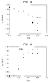
- Figure 5A is a graph detailing methane conversion versus percentage carbon dioxide in feed.
- Figure 5B is a graph detailing carbon dioxide conversion versus percentage carbon dioxide in feed.
-
- Natural gas and an oxygen-containing gas are mixed through
lines 1 and 2 in a simple mixing device 3, with velocity exceeding the natural gas flame velocity so as to avoid flammability. The C/O2 ratio in the mixture is in the range 1.5 to 2.0, preferably in the range 1.6 to 1.9. Optionally, steam or CO2 is added to natural gas to adjust the H2/CO ratio in the product. Optionally, natural gas may be preheated by exchanging heat with the hot product stream or by other means so that the feed mixture temperature reaches about 80 °C or even higher up to 100°C (but this is not preferred). Since partial oxidation reaction is highly exothermic, the reactor is designed as a refractory-lined vessel 4 to achieve good thermal insulation. Themonolith catalyst 6 is located at the bottom, carefully sealed with zirconia cement to prevent leakage of any unreacted feed gas. The top space is then filled with inert blank foam monolith discs 5 to improve the flow distribution and to avoid flammability. A gas distribution means such as a stainless steel distribution plate may be placed between the blank ceramic foam monoliths. - The partial oxidation reaction is preferably carried out at pressures in the range of about 1.0 bar to about 10.0 bar and more preferably in the range of about 1.5 bar to about 3.0 bar. By employing such pressures, carbon formation is completely avoided and addition of steam to prevent carbon formation is not necessary as would be the case for high pressure operation. The main benefit of running the reaction without steam is that the syngas produced has 2:1 H2 to CO ratio which is critical for many applications of syngas. Since the reaction is at comparatively lower pressure, the product syngas is compressed to the desired pressure after cooling.
- The metal catalysts employed in the present invention consist of a ceramic monolith support structure composed of ceria coated on zirconia substrate and coated or impregnated with a transition metal or combinations thereof. As used herein, "metal catalyst" refers to the entire catalyst structure including the metal and the monolith support. The monolith support is generally a ceramic foam-like structure formed from a single structural unit wherein the passages are disposed in either an irregular or regular pattern with spacing between adjacent passages. The single structural unit is used in place of conventional particulate or granular catalysts, which are less desirable in the present process.
Examples of such irregularly patterned monolith supports include filters used for molten metals. Examples of regularly patterned supports include monolith honeycomb (foam) supports used for purifying exhausts from motor vehicles and used in various chemical processes. Preferred are the ceramic foam structures having irregular passages. Both types of monolith supports are well known and commercially available. - The catalyst element typically consists of a ceramic foam monolith composed substantially of zirconia, coated with about 15 to 20 wt. % ceria providing surface area for the metal impregnation, and contains 0.5 to 5 wt. % noble metal, preferably rhodium in metallic form, more preferably about 2 wt. % Rh. Optionally, a transition metal, such as Ni at 2 to 4 wt. % may be used by itself or in combination with Rh. The reactor contains several ceramic monolith foam discs including those with catalyst impregnated on them and the remaining blanks to fill the void space. The blanks can be made of alumina, zirconia, cordierite or mixtures thereof. The impregnated metal (Rh), synergistically with ceria, acts as catalyst for the partial oxidation process. The discs with catalyst have porosity in the range 40 to 70 pores per inch (ppi) to maximize catalyst loading. On the other hand, blank discs have a relatively
high porosity 20 to 40 ppi in order to keep the pressure drop low. The dimensions, i.e. diameter and height, are selected to meet two criteria, namely feed gas space velocity in the range of about 50,000 to 500,000 per hour (expressed as hourly standard volumetric feed flow rate per unit volume of the catalytic monolith), and linear velocity on a similar basis (standard conditions) of about 0.2 to 2 m/s. - On the catalyst surface hydrocarbons and oxygen in the feed mixture react rapidly to produce H2 and CO, along with traces of CO2 and H2O and unreacted methane, as well as heat due to the exothermic nature of the reaction. The hot synthesis gas (H2 + CO) 8 is quickly cooled by quenching water 7 to produce steam and to prevent carbon formation. The reactor design shown in Figure 1 includes a quench system which allows cooling of syngas as it exits the monolith catalyst. The quenching system is designed to permit several modes of operation. For example,
- Minimum quench mode allows maximum heat recovery from syngas by quenching the syngas to a temperature which reduces carbon formation tendency.
- Maximum quench mode allows syngas to be cooled down to 100 to 150 °C which represents a low capital cost solution if heat recovery is not desired.
- Partial quench mode allows the syngas to be cooled down to temperatures suitable for downstream processing, e.g. water-gas shift reaction to convert majority of the CO to H2.
- As mentioned above, the metal catalyst is a singular unit of varying dimensions depending on the size and design of the reactor. In a preferred embodiment, the reactor is a pipe or tube of suitable material and construction having a diameter of between about 1 and 100 inches. The feed gas mixture is fed into one end and the partial oxidation reaction occurs on the metal catalyst with the product gas exiting from the other end. The metal catalyst can also comprise of multiple monolith units to form an assembly of units disposed in end-to-end arrangements. It is preferred that the metal catalyst has porosity and orientation which minimize the pressure drop of the feed gas through the catalyst. Moreover, multiple individual reactors can be used to form an assembly of reactors disposed in a side-by-side arrangement for increased production. For example, multiple pipes or tubes can be packed together as an assembly to form a single reactor unit with each individual pipe containing the metal catalyst.
- The present invention provides an improved partial oxidation process in which the initiation temperature can be as low as about 10° C. The present process eliminates the need for an external heat source or a separate pre-heat step to initiate the reaction thereby increasing the commercial attractiveness of the process. The method according to the invention preferably includes controlled addition of hydrogen to the feed mixture prior to initiation of the partial oxidation while maintaining a proper sequence of introducing the various gas components in the feed mixture to achieve room temperature start-up of this invention.
- Furthermore it has been discovered that the start-up (initiation) at room temperature (above 10 °C) using small amount of H2 is possible only with the use of ceria-coating on the base monolith support, including metal and ceramic monoliths such as stainless steel, zirconia, titania etc. Tests show that room temperature start up is impossible using small amount of H2 with, for example, a zirconia supported catalyst, without ceria coating. these tests are illustrated in Example 1. The preferred operating procedure of the inventive process is as described below:
- 1. Natural gas is first introduced at the desired flow rate.
- 2. Once the natural gas flow reaches its desired set point, i.e. the flow has been established at the desired rate, hydrogen injection into the natural gas begins. This is critical from a safety point of view and to maintain natural gas rich conditions before oxygen is added.
- 3. Oxygen flow is also started once the natural gas flow has reached its desired set point.
- 4. The H2 flow, typically about 0.5 to 4% of the total flow, is maintained for 10 to 30 seconds.
- 5. Start-up of the reaction is indicated by the rapid increase in the catalyst temperature to >400 °C. The start-up can occur before the oxygen flow has reached its set point (i.e. its desired flow rate) demonstrating that hydrogen injection is required for only a short period of time.
-
- Furthermore, the start-up at room temperature is also possible with continuous flow of CO2 as reactant in the feed mixture. Shown as Figure 4, the preferred operating procedure of the inventive process is as described below:
- 1. Natural gas and carbon dioxide are first introduced at the desired flow rate.
- 2. Once the natural gas and carbon dioxide flows reach their desired set points, i.e. the flows have been established at the desired rates, hydrogen injection begins.
- 3. Oxygen flow is then started.
- 4. The H2 flow, typically about 0.5 to 4% of the total flow, is maintained for 10 to 30 seconds.
- 5. Start-up of the reaction is indicated by the rapid increase in the catalyst temperature to >400 °C.
-
- It should be pointed out that addition of CO2 effectively controls the front temperature of catalyst as well as controls the heat-up rate of the catalyst bed. Therefore the initial thermal shock on monolith catalyst can be avoided through this method.
- Hydrogen is preferably fed continuously to the feed gas mixture of natural gas and oxygen. To maintain optimum efficiency in the process, the monolith catalyst needs to be in a reduced state. During start-ups, shutdowns and upset conditions, the monolith catalyst can become exposed to oxygen which can deactivate the monolith catalyst, particularly when the catalyst is hot. By ensuring a continuous feed of hydrogen to the gas feed mixture, the monolith catalyst remains in the reduced form and maintains its catalytic activity.
- The hydrogen may be supplied continuously from a hydrogen production plant. The hydrogen production plant may be a pressure swing adsorption unit or a cryogenic rectification plant. The hydrogen may be a hydrogen-rich stream which exits from a carbon monoxide pressure swing adsorption unit or the cold box of the cryogenic rectification plant. Alternatively, hydrogen may be obtained from a product syngas after heat recovery and cooling.
- As described in Figure 2, a schematic process for the production of hydrogen and carbon monoxide is depicted.
Lines Line 11 delivers hydrogen to the feed mixer A and is used in the embodiments of the invention where hydrogen is injected during the start-up process. -
Line 14 exits the feed mixer A and delivers oxygen, hydrogen and natural gas to the monolith reactor B where the monolith catalyst is housed. The monolith catalyst is the ceramic monolith support structure composed of ceria coated on zirconia substrate and coated or impregnated with a transition metal or combinations thereof. The partial oxidation process occurs therein and the resulting product gas stream, primarily carbon monoxide and hydrogen, are delivered throughline 16 to the cold box or carbon monoxide pressure swing adsorption unit C whereby carbon monoxide is separated from the product gas stream. Product carbon monoxide leaves vialine 18 and the remaining portion of the product gas leaves throughline 20 to hydrogen pressure swing adsorption unit D where hydrogen is separated from the product gas and leaves vialine 22. - The product gas exiting the cold box or carbon monoxide pressure swing adsorption unit C is hydrogen rich and part of this stream is diverted at
valve 21 and directed alongline 23 to the feed mixer A. This flow of hydrogen-rich gas can be continuously diverted from the cold box or carbon monoxide pressure swing adsorption unit C during the production process, thereby achieving a steady state whereby hydrogen is continuously present in the feed gas mix. - Alternatively as depicted in Figure 3, rather than having
valve 21 divert hydrogen-rich gas throughline 23 to the feed mixer A, avalve 25 is placed in line16. This valve connects withline 27 which connects to feed mixer A. This embodiment diverts product gas, containing primarily carbon monoxide and hydrogen, throughvalve 25 andline 27, back to the feed mixer A whereby hydrogen will continuously mix with the feed gas as long as the partial oxidation is occurring. This also achieves a steady state presence of hydrogen in the feed gas mixture. - The method according to the present invention is unique in that the hydrocarbon-oxygen mixture is fed to the reactor typically at room temperature, and a small amount of H2 is injected for a short time to initiate the partial oxidation reaction. We have also found that injection of hydrogen on its own is not enough to achieve room temperature start-up. The room temperature start-up can only be achieved by hydrogen injection combined with correct sequence of introducing natural gas and oxygen. Start-up at room temperature (above 10°C) using a small amount of H2 is possible primarily by the use of ceria-coating on the base monolith support, including metal and ceramic monoliths such as stainless steel, zirconia, titania etc. Furthermore, the timing, amount and ensuring safety are critical parts of hydrogen injection as practised in this invention. Thus, a further improvement is achieved in the start-up procedure.
- To shut down the reactor, N2 flow is first started through the reactor, O2 in the feed is then turned off, and the natural gas flow is turned off last. Proper care is taken to ascertain that no flammable or carbon formation conditions exist within the system. It is important to make sure that oxygen is not present in the reactor when there is no natural gas flow during shut-down in order to prevent oxidation of the catalyst which, if occurs, will deactivate the catalyst.
- Another embodiment of the present invention is a process for the partial oxidation of hydrocarbons such as methane (natural gas) by contacting a feed containing the hydrocarbon, O2 and CO2 through a catalyst comprising rhodium supported on a ceria-coated monolith. The presence of CO2 leads to convert some product H2 from partial oxidation reaction to CO. Such a reaction will significantly increase CO production. Addition of CO2 also increases the operating window for partial oxidation in terms of flammability. The conversion of CO2 can be further improved by preheating the feed mixture to a higher temperature. It was found that addition of up to about 30 volume % CO2 causes no significant deterioration in performance, and indeed, about 30% conversion of CO2 is achieved in the short contact time reactor of this invention. The reaction is preferably performed at a low pressure, which helps prevent carbon formation under these conditions.
- It has also been observed that, when using the method according to the invention, the conversion of methane to hydrogen and carbon monoxide depends on both, space velocity and linear velocity at a fixed carbon to oxygen ratio in the feed. In addition, multiple layers of catalyst monoliths not only allow higher throughput capability at the same space velocity but also give better methane conversion at the same linear velocity. Example 2 illustrates the effect of layers of monoliths on the process performance.
- The following examples illustrate the method according to the invention.
- A zirconia monolith having 45 pores per inch, 0.7 inch in diameter and 0.39 inch long, was first coated with 20 wt. % ceria and then impregnated with 2% by weight of rhodium metal to prepare the metal catalyst. Detailed preparation method can be found in co-pending US patent
application Serial Number 10/143,705 (corresponding to EP-A-1 369 381 due to be published on 10 December 2003). The reactor containing the metal catalyst monolith was purged with nitrogen gas at 10° C for 60 minutes. - Methane was first introduced at a flow rate of 8.8 slpm. Once this flow rate was established a small amount of H2 (0.5 slpm) was injected into the methane line for up to 30 seconds. At the same time, O2 flow was started and adjusted to obtain the desired C/O2 ratio of 1.75. Start-up of the reaction was indicated by the rapid increase in the catalyst temperature to >800 °C within a few seconds with the production of hydrogen and carbon monoxide. Therefore only about 4% H2 in feed mixture is used for only 30 seconds to start up the partial oxidation of methane. The gases had not been preheated.
- A metal catalyst was prepared as described in Example 1. The same amount of rhodium metal was loaded on the ceria-coated zirconia support.
- A premixed gas mixture containing methane (8.8 slpm), oxygen (5.0 slpm) and hydrogen (0.5 slpm) was passed into the reactor containing the metal catalyst at 10° C. The reaction could not be initiated until hydrogen amount was increased to 22 mol % (3 slpm). This shows the importance of the sequence of addition of different gases in the feed mixture.
- A metal catalyst was prepared as described in Example 1, except that the monolith support was made of zirconia. The same amount of rhodium metal was loaded on the zirconia support, without any ceria coating as described in Example 1.
- When attempting to start the reaction by following the procedures described in Example 1 using hydrogen injection, the reaction could not be initiated until a temperature of about 150° C was reached. This clearly shows the synergistic role played by ceria.
- To compare the effect of linear velocity and space velocity, monolith catalysts, as described in Example 1, of two different diameters (0.7" and 1 ") (1.8 and 2.54 mm) were used. To compare results on the same catalyst volume basis, data with four stacked catalyst discs of 0.7" (1.8mm) diameter x 0.39" (1 mm) thickness are compared to those with two 1 "x 0.39" monolith catalysts. A feed mixture containing 64% methane and 36% oxygen was passed through the reactor, following the same start up procedure as in Example 1. Here space velocity is defined as total feed gas flow rate divided by the catalytic monolith volume and linear velocity is defined as total feed gas flow rate divided by the cross-sectional area of the catalytic monolith. Table 1 shows that, for the same space velocity and at the same reaction conditions, increasing linear velocity will increase methane conversion with better H2 and CO selectivity. On the other hand, for the same linear velocity, lower space velocity results in better methane conversion and appreciably less methane slip. In other words, increasing L/D aspect ratio of catalytic monolith improved performance of partial oxidation reaction.
2% Rh on 20% CeO2 coated ZrO2 monolith Space Velocity Y Linear Velocity Conversion % Selectivity % (1/hr) (m/s) CH4 H2 CO 4 x 0.7" x 0.39" 86036 0.87 97.8 95.8 93.9 2 x 1 " x 0.39" 85810 0.47 97.0 96.0 92.0 2 x 1 " x 0.39" 158464 0.87 95.6 95.0 93.2 4 x 0.7" x 0.39" 138817 1.40 99.0 96.7 93.7 2 x 1 " x 0.39" 138731 0.76 97.2 95.3 93.2 - A partial oxidation reaction was initiated following the same procedure as described in Example 1 with the same metal catalyst, which was used in Example 1. A gaseous mixture containing methane and oxygen at carbon to oxygen ratio of 1.75 and between 0 to about 30% by volume of carbon dioxide was then fed to the reactor containing the monolith catalyst. This mixture was different from the mixture which was used to initiate the reaction. This feed mixture was fed at a space velocity of 150,000 hr-1. The reaction temperature decreased from 1020° to 750° C due to endothermic reverse gas shift reaction. The typical product gas contained 39% hydrogen, 33% carbon monoxide, 13.1 % carbon dioxide, 1.3% methane and 12.6% water. The conversion rate of methane and carbon dioxide were calculated from the measured concentrations in the product. The results are shown in Figures 5a and 5b below. When feed gas mixture was preheated to 300 °C, there is a slight increase in both CH4 and CO2 conversion. The conversion measurements were calculated through element material balance.
Claims (17)
- A method for the partial catalytic oxidation of hydrocarbon to produce hydrogen and carbon monoxide, by contacting a reduced metal catalyst consisting essentially of a transition metal selected from the group consisting of nickel, cobalt, iron, platinum, palladium, iridium, rhenium, ruthenium, rhodium, osmium and combinations thereof supported on or in a ceria-coated zirconia monolith support with a flow of a mixture of a hydrocarbon-containing feed gas and an oxygen-containing feed gas, wherein the partial oxidation is initiated at a temperature of at least 10°C but less than 100°C, the mixture including hydrogen prior to initiation.
- A method as claimed in claim 1, wherein the flow of said hydrogen is continuous.
- A method as claimed in claim 1, wherein the hydrogen is supplied only for a period of from 10 to 30 seconds.
- A method as claimed in any one of the preceding claims, wherein no external heat source or preheating step is employed.
- A method as claimed in any one of the preceding claims, in which the initiation temperature is room temperature.
- A method as claimed in any one of the preceding claims, wherein the initiation of the partial oxidation is conducted by first establishing a flow of the hydrocarbon containing feed gas and then adding the oxygen-containing feed gas and the hydrogen so as to form the said mixture.
- A method as claimed in claim 6, wherein the additions of the hydrogen and the oxygen-containing feed gas to the flow of the hydrocarbon-containing feed gas are commenced simultaneously.
- A method as claimed in any one of the preceding claims, wherein said reduced metal catalyst is a rhodium catalyst supported on or in a ceria-coated zirconia monolith support and said mixture further comprises carbon dioxide.
- A method as claimed in any one of the preceding claims, wherein the said mixture includes carbon dioxide prior to the initiation of the partial oxidation reaction.
- A method as claimed in claim 9, wherein the carbon dioxide is added continuously to the said mixture.
- A method as claimed in claim 9 or claim 10, wherein the carbon dioxide is present in the said mixture in an amount up to about 80% by volume.
- A method as claimed in any one of the preceding claims, wherein the pressure of said mixture is about 1.0 bar to about 10.0 bar.
- A method as claimed in claim 11, wherein the said pressure is in the range of 1.5 to 3.0 bar.
- A method as claimed in any one of the preceding claims, wherein said ceria-coated zirconia monolith support is about 5% to about 30% ceria by weight.
- A method as claimed in any one of the preceding claims, wherein said hydrogen is present in an amount of about 0.5 to about 4.0 percent by volume of the total flow of said mixture.
- A method as claimed in any one of the preceding claims, wherein the ratio of hydrogen to carbon monoxide produced by said partial oxidation is about 2:1 hydrogen to carbon monoxide.
- A method as claimed in any one of the preceding claims, wherein said partial oxidation is performed in a reactor comprising a vessel containing said supported catalyst in the form of at least one ceramic foam monolith support disc impregnated with said reduced catalyst and at least one blank ceramic foam disc.
Applications Claiming Priority (4)
| Application Number | Priority Date | Filing Date | Title |
|---|---|---|---|
| US43607402P | 2002-12-23 | 2002-12-23 | |
| US436074P | 2002-12-23 | ||
| US10/657,610 US7090826B2 (en) | 2002-12-23 | 2003-09-08 | Monolith based catalytic partial oxidation process for syngas production |
| US657610 | 2003-09-08 |
Publications (2)
| Publication Number | Publication Date |
|---|---|
| EP1433746A2 true EP1433746A2 (en) | 2004-06-30 |
| EP1433746A3 EP1433746A3 (en) | 2008-03-26 |
Family
ID=32397269
Family Applications (1)
| Application Number | Title | Priority Date | Filing Date |
|---|---|---|---|
| EP03257653A Withdrawn EP1433746A3 (en) | 2002-12-23 | 2003-12-05 | Catalytic partial oxidation method |
Country Status (14)
| Country | Link |
|---|---|
| US (2) | US7090826B2 (en) |
| EP (1) | EP1433746A3 (en) |
| JP (1) | JP2004203737A (en) |
| KR (1) | KR20040057953A (en) |
| CN (1) | CN100575247C (en) |
| AU (1) | AU2003264634C1 (en) |
| CA (1) | CA2450157A1 (en) |
| MY (1) | MY134650A (en) |
| NO (1) | NO20035493L (en) |
| NZ (1) | NZ529798A (en) |
| PL (1) | PL203313B1 (en) |
| SG (1) | SG135004A1 (en) |
| TW (1) | TWI312294B (en) |
| ZA (1) | ZA200309254B (en) |
Cited By (3)
| Publication number | Priority date | Publication date | Assignee | Title |
|---|---|---|---|---|
| EP2165009A4 (en) * | 2007-06-06 | 2012-08-08 | Linde Llc | Integrated processes for generating carbon monoxide for carbon nanomaterial production |
| WO2012177136A1 (en) * | 2011-06-23 | 2012-12-27 | Stamicarbon B.V. Acting Under The Name Of Mt Innovation Center | Process for producing a syngas intermediate suitable for the production of hydrogen |
| WO2019175476A1 (en) * | 2018-03-13 | 2019-09-19 | Teknologian Tutkimuskeskus Vtt Oy | Method and apparatus for producing carbon monoxide |
Families Citing this family (22)
| Publication number | Priority date | Publication date | Assignee | Title |
|---|---|---|---|---|
| US20060058184A1 (en) * | 2000-03-02 | 2006-03-16 | Weibin Jiang | Metal catalyst and method of preparation and use |
| KR100599668B1 (en) * | 2004-08-19 | 2006-07-12 | 한국과학기술연구원 | Pile of catalyst compacts for partial oxidation reforming of fuel, fuel reforming apparatus and fuel reforming method using same |
| BRPI0517600B1 (en) * | 2004-12-23 | 2018-11-21 | Saudi Arabian Oil Co | thermo-neutral reform process to produce a hydrogen-rich synthetic gas |
| US20070013144A1 (en) * | 2005-07-13 | 2007-01-18 | Seungdoo Park | Reactor sealing methods |
| EP1820569A1 (en) * | 2006-01-20 | 2007-08-22 | Ineos Europe Limited | Process for contacting a hydrocarbon and an oxygen-containing gas with a catalyst bed |
| US20080075655A1 (en) * | 2006-09-21 | 2008-03-27 | Lev Davydov | Gas mixing device and methods of use |
| US20080260631A1 (en) | 2007-04-18 | 2008-10-23 | H2Gen Innovations, Inc. | Hydrogen production process |
| JP5348938B2 (en) * | 2008-04-01 | 2013-11-20 | エア・ウォーター株式会社 | Carbon monoxide gas generator and method |
| US20090123354A1 (en) * | 2007-11-14 | 2009-05-14 | Deng-Yang Jan | Selective Oxidation Agent of Hydrocarbons to Synthesis Gas Based on Separate Particles of O-Carrier and Hydrocarbon Activator |
| EP2202201B1 (en) * | 2008-12-23 | 2016-04-20 | Clariant Prodotti (Italia) SpA | Ammonia oxidation catalysts |
| US20100304268A1 (en) * | 2009-05-28 | 2010-12-02 | Tetsuo Kawamura | Ternary alloy catalysts for fuel cells |
| US8673219B2 (en) * | 2010-11-10 | 2014-03-18 | Invention Science Fund I | Nasal passage insertion device for treatment of ruminant exhalations |
| KR101480801B1 (en) | 2013-05-08 | 2015-01-12 | 한국화학연구원 | Monolith type reforming catalyst, preparation method thereof and process for syn gas |
| AU2014346747B2 (en) | 2013-11-06 | 2017-02-09 | WATT Fuel Cell Corp | Integrated gaseous fuel CPOX reformer and fuel cell systems, and methods of producing electricity |
| US9627699B2 (en) | 2013-11-06 | 2017-04-18 | Watt Fuel Cell Corp. | Gaseous fuel CPOX reformers and methods of CPOX reforming |
| US9627700B2 (en) | 2013-11-06 | 2017-04-18 | Watt Fuel Cell Corp. | Liquid fuel CPOX reformer and fuel cell systems, and methods of producing electricity |
| JP6357242B2 (en) | 2013-11-06 | 2018-07-11 | ワット・フューエル・セル・コーポレイションWatt Fuel Cell Corp. | Fuel catalyst partial oxidation reforming reactor with manifold for management of gaseous reaction medium flow to chemical reactor |
| CN105705226B (en) | 2013-11-06 | 2018-03-27 | 瓦特燃料电池公司 | Liquid fuel CPOX reformer and catalytic partial oxidation reforming method |
| CN105873854B (en) | 2013-11-06 | 2019-02-05 | 瓦特燃料电池公司 | A reformer using perovskite as its structural component |
| CN108837836B (en) * | 2018-06-22 | 2021-04-13 | 上海纳米技术及应用国家工程研究中心有限公司 | Preparation method of integral material for benzene purification, product and application thereof |
| JP7320321B2 (en) | 2019-08-29 | 2023-08-03 | ワット・フューエル・セル・コーポレイション | Multi-tubular chemical reactor with igniter for gas phase exothermic reaction initiation |
| US12341226B1 (en) | 2024-08-07 | 2025-06-24 | Watt Fuel Cell Corp. | Integrated CPOX/stream reformer and fuel cell system |
Citations (6)
| Publication number | Priority date | Publication date | Assignee | Title |
|---|---|---|---|---|
| US4879253A (en) | 1987-09-28 | 1989-11-07 | Oki Electric Industry Co., Ltd. | Method for fabricating a semiconductor device using a BPSG layer containing high concentrations of phosphorus and boron |
| WO1999048805A1 (en) | 1998-03-24 | 1999-09-30 | Johnson Matthey Public Limited Company | Catalytic generation of hydrogen |
| EP1134188A2 (en) | 2000-03-02 | 2001-09-19 | The Boc Group, Inc. | Catalytic partial oxidation of hydrocarbons |
| US20020115730A1 (en) | 2000-09-05 | 2002-08-22 | Allison Joe D. | Lanthanide-promoted rhodium catalysts and process for producing synthesis gas |
| US6458334B1 (en) | 2000-03-02 | 2002-10-01 | The Boc Group, Inc. | Catalytic partial oxidation of hydrocarbons |
| EP1369381A1 (en) | 2002-05-09 | 2003-12-10 | The Boc Group, Inc. | Metal catalyst, its method of preparation and its use |
Family Cites Families (47)
| Publication number | Priority date | Publication date | Assignee | Title |
|---|---|---|---|---|
| GB1412142A (en) * | 1972-01-14 | 1975-10-29 | Foseco Int | Gas reactors |
| GB1399137A (en) | 1972-07-17 | 1975-06-25 | British Petroleum Co | Production of reducing gases |
| IT1021774B (en) | 1974-10-11 | 1978-02-20 | Centro Speriment Metallurg | PROCESS FOR THE PREPARATION OF REDUCING GASES |
| DE2907106C2 (en) * | 1979-02-23 | 1985-12-19 | Degussa Ag, 6000 Frankfurt | Catalytic converter and its use for cleaning exhaust gases from internal combustion engines |
| GB2070957B (en) * | 1980-03-10 | 1984-08-30 | Bridgestone Tire Co Ltd | Catalytic device for purification of exhaust gas |
| FR2530489B1 (en) | 1982-07-26 | 1987-02-27 | Pro Catalyse | PROCESS FOR THE MANUFACTURE OF CATALYSTS FOR THE TREATMENT OF EXHAUST GASES FROM INTERNAL COMBUSTION ENGINES |
| US5023276A (en) | 1982-09-30 | 1991-06-11 | Engelhard Corporation | Preparation of normally liquid hydrocarbons and a synthesis gas to make the same, from a normally gaseous hydrocarbon feed |
| US4844837A (en) | 1982-09-30 | 1989-07-04 | Engelhard Corporation | Catalytic partial oxidation process |
| US4522894A (en) | 1982-09-30 | 1985-06-11 | Engelhard Corporation | Fuel cell electric power production |
| CA1213875A (en) | 1982-11-29 | 1986-11-12 | Shigeo Uno | Catalyst for catalytic combustion |
| FR2568143B1 (en) | 1984-07-30 | 1986-12-05 | Prod Catalyse Ste Fse | CATALYST AND METHOD FOR THE TREATMENT OF EXHAUST GASES FROM INTERNAL COMBUSTION ENGINES |
| US4680272A (en) * | 1985-10-23 | 1987-07-14 | University Of California | Method for detecting molecules containing amine or thiol groups |
| GB8623482D0 (en) | 1986-09-30 | 1986-11-05 | Johnson Matthey Plc | Catalytic generation of hydrogen |
| AU595655B2 (en) | 1986-11-04 | 1990-04-05 | Kabushiki Kaisha Toyota Chuo Kenkyusho | Catalyst for the purification of exhaust gas |
| EP0303438A3 (en) | 1987-08-14 | 1989-12-27 | DAVY McKEE CORPORATION | Production of synthesis gas from hydrocarbonaceous feedstock |
| DE3873258D1 (en) | 1987-10-30 | 1992-09-03 | Degussa | PLATINUM-FREE THREE-WAY CATALYST. |
| US5232889A (en) | 1989-11-27 | 1993-08-03 | Rhone-Poulenc Chimie | Supported catalysts |
| GB9028034D0 (en) | 1990-12-24 | 1991-02-13 | Isis Innovation | Improved processes for the conversion of methane to synthesis gas |
| WO1993001130A1 (en) | 1991-07-02 | 1993-01-21 | University Of Warwick | Catalysts for the production of carbon monoxide |
| EP0524643B1 (en) | 1991-07-25 | 1996-04-24 | Corning Incorporated | Pore impregnated catalyst device |
| NZ245394A (en) | 1991-12-20 | 1995-03-28 | Idemitsu Kosan Co | Preparation process for synthesis gases using methane, oxygen and a catalyst |
| US5411927A (en) | 1992-08-14 | 1995-05-02 | Council Of Scientific & Industrial Research | Process of preparing composite catalysts for production of synthesis gas by oxidative conversion of methane or natural gas |
| US5965481A (en) | 1993-05-14 | 1999-10-12 | Institut Francais Du Petrole | Process for preparing a catalyst suitable for the treatment of exhaust gases from internal combustion engines |
| US5580536A (en) | 1993-06-21 | 1996-12-03 | Santoku Metal Industry Co., Ltd. | Composite oxide having oxygen absorbing and desorbing capability and method for preparing same |
| US5648582A (en) | 1993-08-20 | 1997-07-15 | Regents Of The University Of Minnesota | Stable, ultra-low residence time partial oxidation |
| EP0640561B1 (en) | 1993-08-24 | 1998-11-11 | Shell Internationale Researchmaatschappij B.V. | Process for the catalytic partial oxidation of hydrocarbons |
| IT1272532B (en) | 1993-08-27 | 1997-06-23 | Snam Progetti | PARTIAL CATALYTIC OXIDATION PROCESS OF NATURAL GAS TO OBTAIN SYNTHESIS GAS AND FORMALDEHYDE |
| NZ264970A (en) | 1993-11-29 | 1997-02-24 | Shell Int Research | Hydrocarbon oxidation; catalytic partial oxidation of hydrocarbon feedstock, preparation of carbon monoxide/hydrogen mixture, details regarding catalyst arrangement |
| US5955481A (en) * | 1994-03-28 | 1999-09-21 | Nissan Chemical Industries, Ltd. | Pyridine type thiazolidines |
| US5441581A (en) | 1994-06-06 | 1995-08-15 | Praxair Technology, Inc. | Process and apparatus for producing heat treatment atmospheres |
| DZ1918A1 (en) | 1994-08-02 | 2002-02-17 | Shell Internaional Res Mij B V | Process for partial catalytic oxidation of hydrocarbons. |
| US5658497A (en) | 1995-12-05 | 1997-08-19 | Shell Oil Company | Process for the catalytic partial oxidation of hydrocarbons using a certain catalyst support |
| US6143691A (en) | 1995-12-27 | 2000-11-07 | Ict Co., Ltd | Purifying catalyst for exhaust gas from internal combustion engine |
| AU6398698A (en) | 1997-02-14 | 1998-09-08 | Shell Internationale Research Maatschappij B.V. | Catalytic partial oxidation of hydrocarbons |
| IT1291205B1 (en) | 1997-03-18 | 1998-12-29 | Rivoira S P A | PROCEDURE FOR THE GENERATION OF A PROTECTIVE ATMOSPHERE WITH LOW DEW POINT AND FREE FROM OXYGEN, FOR THE PERFORMANCE OF |
| US5883138A (en) | 1997-04-25 | 1999-03-16 | Exxon Research And Engineering Company | Rapid injection catalytic partial oxidation process and apparatus for producing synthesis gas (law 562) |
| US5976721A (en) | 1997-09-15 | 1999-11-02 | Limaye; Santosh Y. | Chemical cogeneration process |
| US6254807B1 (en) | 1998-01-12 | 2001-07-03 | Regents Of The University Of Minnesota | Control of H2 and CO produced in partial oxidation process |
| JP4204692B2 (en) | 1998-03-30 | 2009-01-07 | 株式会社日本触媒 | Nitrogen oxide removal catalyst, method for producing the same, and method for removing nitrogen oxides using the catalyst |
| US6329434B1 (en) | 1999-06-04 | 2001-12-11 | Exxonmobil Research And Engineering Company | Catalytic partial oxidation with improved ignition system |
| BR0014995A (en) | 1999-10-29 | 2002-06-18 | Exxon Res And Egineering Compa | Catalytic partial oxidation process |
| US6733692B2 (en) * | 2000-04-20 | 2004-05-11 | Conocophillips Company | Rhodium foam catalyst for the partial oxidation of hydrocarbons |
| KR200203959Y1 (en) * | 2000-05-22 | 2000-11-15 | 백대휘 | Necktie |
| US6527980B1 (en) * | 2000-10-12 | 2003-03-04 | Air Products And Chemicals, Inc. | Reforming with intermediate reactant injection |
| WO2002066403A1 (en) * | 2001-02-16 | 2002-08-29 | Conoco Inc. | Supported rhodium-spinel catalysts and process for producing synthesis gas |
| JP4648567B2 (en) * | 2001-05-11 | 2011-03-09 | Jx日鉱日石エネルギー株式会社 | Autothermal reforming catalyst and method for producing fuel gas for fuel cell |
| US20040052725A1 (en) * | 2002-06-28 | 2004-03-18 | Conocophillips Company | Oxidized metal catalysts and process for producing synthesis gas |
-
2003
- 2003-09-08 US US10/657,610 patent/US7090826B2/en not_active Expired - Fee Related
- 2003-11-20 CA CA002450157A patent/CA2450157A1/en not_active Abandoned
- 2003-11-27 NZ NZ529798A patent/NZ529798A/en unknown
- 2003-11-27 ZA ZA200309254A patent/ZA200309254B/en unknown
- 2003-12-01 AU AU2003264634A patent/AU2003264634C1/en not_active Ceased
- 2003-12-05 EP EP03257653A patent/EP1433746A3/en not_active Withdrawn
- 2003-12-10 NO NO20035493A patent/NO20035493L/en not_active Application Discontinuation
- 2003-12-11 SG SG200307409-3A patent/SG135004A1/en unknown
- 2003-12-12 TW TW092135194A patent/TWI312294B/en not_active IP Right Cessation
- 2003-12-19 MY MYPI20034889A patent/MY134650A/en unknown
- 2003-12-22 PL PL364198A patent/PL203313B1/en not_active IP Right Cessation
- 2003-12-22 JP JP2003424604A patent/JP2004203737A/en not_active Ceased
- 2003-12-22 KR KR1020030094618A patent/KR20040057953A/en not_active Ceased
- 2003-12-23 CN CN200310124500A patent/CN100575247C/en not_active Expired - Fee Related
-
2006
- 2006-05-10 US US11/431,796 patent/US20060204415A1/en not_active Abandoned
Patent Citations (6)
| Publication number | Priority date | Publication date | Assignee | Title |
|---|---|---|---|---|
| US4879253A (en) | 1987-09-28 | 1989-11-07 | Oki Electric Industry Co., Ltd. | Method for fabricating a semiconductor device using a BPSG layer containing high concentrations of phosphorus and boron |
| WO1999048805A1 (en) | 1998-03-24 | 1999-09-30 | Johnson Matthey Public Limited Company | Catalytic generation of hydrogen |
| EP1134188A2 (en) | 2000-03-02 | 2001-09-19 | The Boc Group, Inc. | Catalytic partial oxidation of hydrocarbons |
| US6458334B1 (en) | 2000-03-02 | 2002-10-01 | The Boc Group, Inc. | Catalytic partial oxidation of hydrocarbons |
| US20020115730A1 (en) | 2000-09-05 | 2002-08-22 | Allison Joe D. | Lanthanide-promoted rhodium catalysts and process for producing synthesis gas |
| EP1369381A1 (en) | 2002-05-09 | 2003-12-10 | The Boc Group, Inc. | Metal catalyst, its method of preparation and its use |
Cited By (7)
| Publication number | Priority date | Publication date | Assignee | Title |
|---|---|---|---|---|
| EP2165009A4 (en) * | 2007-06-06 | 2012-08-08 | Linde Llc | Integrated processes for generating carbon monoxide for carbon nanomaterial production |
| WO2012177136A1 (en) * | 2011-06-23 | 2012-12-27 | Stamicarbon B.V. Acting Under The Name Of Mt Innovation Center | Process for producing a syngas intermediate suitable for the production of hydrogen |
| CN103648971A (en) * | 2011-06-23 | 2014-03-19 | 代表Mt创新中心的斯塔米卡邦有限公司 | Process for producing a syngas intermediate suitable for the production of hydrogen |
| EA025547B1 (en) * | 2011-06-23 | 2017-01-30 | СТАМИКАРБОН Б.В. ЭКТИНГ АНДЕР ДЗЕ НЕЙМ ОФ ЭмТи ИННОВЕЙШН СЕНТЕР | Process for producing a syngas intermediate suitable for the production of hydrogen |
| US9701535B2 (en) | 2011-06-23 | 2017-07-11 | Stamicarbon B.V. | Process for producing a syngas intermediate suitable for the production of hydrogen |
| CN103648971B (en) * | 2011-06-23 | 2018-04-17 | 代表Mt创新中心的斯塔米卡邦有限公司 | Preparation method suitable for the synthesis gas intermediate for preparing hydrogen |
| WO2019175476A1 (en) * | 2018-03-13 | 2019-09-19 | Teknologian Tutkimuskeskus Vtt Oy | Method and apparatus for producing carbon monoxide |
Also Published As
| Publication number | Publication date |
|---|---|
| KR20040057953A (en) | 2004-07-02 |
| EP1433746A3 (en) | 2008-03-26 |
| ZA200309254B (en) | 2004-05-26 |
| PL364198A1 (en) | 2004-06-28 |
| TW200417407A (en) | 2004-09-16 |
| NZ529798A (en) | 2004-10-29 |
| US7090826B2 (en) | 2006-08-15 |
| MY134650A (en) | 2007-12-31 |
| CA2450157A1 (en) | 2004-06-23 |
| NO20035493L (en) | 2004-06-24 |
| US20060204415A1 (en) | 2006-09-14 |
| AU2003264634C1 (en) | 2009-01-29 |
| TWI312294B (en) | 2009-07-21 |
| PL203313B1 (en) | 2009-09-30 |
| JP2004203737A (en) | 2004-07-22 |
| AU2003264634B2 (en) | 2008-07-24 |
| NO20035493D0 (en) | 2003-12-10 |
| AU2003264634A1 (en) | 2004-07-08 |
| SG135004A1 (en) | 2007-09-28 |
| CN1509980A (en) | 2004-07-07 |
| US20040120888A1 (en) | 2004-06-24 |
| CN100575247C (en) | 2009-12-30 |
Similar Documents
| Publication | Publication Date | Title |
|---|---|---|
| US7090826B2 (en) | Monolith based catalytic partial oxidation process for syngas production | |
| US6458334B1 (en) | Catalytic partial oxidation of hydrocarbons | |
| US6254807B1 (en) | Control of H2 and CO produced in partial oxidation process | |
| EP1403216B1 (en) | Process for the preparation of synthesis gas | |
| CA2442491C (en) | Process for the production of synthesis gas | |
| US4863707A (en) | Method of ammonia production | |
| US7150866B2 (en) | Catalyst for autothermal reforming of hydrocarbons with increased water gas shift activity | |
| AU2003204567B2 (en) | Stabilized nickel-containing catalysts and process for production of syngas | |
| AU777809B2 (en) | Catalytic monolith made of ceria and titania | |
| WO1990006282A1 (en) | Production of methanol from hydrocarbonaceous feedstock | |
| AU2003203688A1 (en) | Gas recovery process | |
| US7544342B2 (en) | Hydrogen production process | |
| US20060168887A1 (en) | Method for producing a fuel gas containing hydrogen for electrochemical cells and associated device | |
| WO1998049093A1 (en) | Low temperature process for producing synthesis gas | |
| HK1065024A (en) | Monolith based catalytic partial oxidation process for syngas production |
Legal Events
| Date | Code | Title | Description |
|---|---|---|---|
| PUAI | Public reference made under article 153(3) epc to a published international application that has entered the european phase |
Free format text: ORIGINAL CODE: 0009012 |
|
| AK | Designated contracting states |
Kind code of ref document: A2 Designated state(s): AT BE BG CH CY CZ DE DK EE ES FI FR GB GR HU IE IT LI LU MC NL PT RO SE SI SK TR |
|
| AX | Request for extension of the european patent |
Extension state: AL LT LV MK |
|
| PUAL | Search report despatched |
Free format text: ORIGINAL CODE: 0009013 |
|
| AK | Designated contracting states |
Kind code of ref document: A3 Designated state(s): AT BE BG CH CY CZ DE DK EE ES FI FR GB GR HU IE IT LI LU MC NL PT RO SE SI SK TR |
|
| AX | Request for extension of the european patent |
Extension state: AL LT LV MK |
|
| 17P | Request for examination filed |
Effective date: 20080911 |
|
| AKX | Designation fees paid |
Designated state(s): AT BE BG CH CY CZ DE DK EE ES FI FR GB GR HU IE IT LI LU MC NL PT RO SE SI SK TR |
|
| 17Q | First examination report despatched |
Effective date: 20090209 |
|
| RAP1 | Party data changed (applicant data changed or rights of an application transferred) |
Owner name: LINDE, INC. |
|
| STAA | Information on the status of an ep patent application or granted ep patent |
Free format text: STATUS: THE APPLICATION IS DEEMED TO BE WITHDRAWN |
|
| 18D | Application deemed to be withdrawn |
Effective date: 20100508 |