EP1433638A1 - Open roof assembly for a vehicle - Google Patents
Open roof assembly for a vehicle Download PDFInfo
- Publication number
- EP1433638A1 EP1433638A1 EP02080638A EP02080638A EP1433638A1 EP 1433638 A1 EP1433638 A1 EP 1433638A1 EP 02080638 A EP02080638 A EP 02080638A EP 02080638 A EP02080638 A EP 02080638A EP 1433638 A1 EP1433638 A1 EP 1433638A1
- Authority
- EP
- European Patent Office
- Prior art keywords
- closure means
- folding
- cloth
- inner cloth
- vehicle
- Prior art date
- Legal status (The legal status is an assumption and is not a legal conclusion. Google has not performed a legal analysis and makes no representation as to the accuracy of the status listed.)
- Granted
Links
- 239000004744 fabric Substances 0.000 claims abstract description 99
- 238000007665 sagging Methods 0.000 description 4
- 230000002035 prolonged effect Effects 0.000 description 1
- 238000007493 shaping process Methods 0.000 description 1
Images

Classifications
-
- B—PERFORMING OPERATIONS; TRANSPORTING
- B60—VEHICLES IN GENERAL
- B60J—WINDOWS, WINDSCREENS, NON-FIXED ROOFS, DOORS, OR SIMILAR DEVICES FOR VEHICLES; REMOVABLE EXTERNAL PROTECTIVE COVERINGS SPECIALLY ADAPTED FOR VEHICLES
- B60J7/00—Non-fixed roofs; Roofs with movable panels, e.g. rotary sunroofs
- B60J7/02—Non-fixed roofs; Roofs with movable panels, e.g. rotary sunroofs of sliding type, e.g. comprising guide shoes
- B60J7/06—Non-fixed roofs; Roofs with movable panels, e.g. rotary sunroofs of sliding type, e.g. comprising guide shoes with non-rigid element or elements
Definitions
- the invention relates to an open roof assembly for a vehicle, comprising a roof opening defined in the roof of the vehicle and a foldable closure means for closing and opening said roof opening, which closure means comprises an outer cloth and an inner cloth mutually spaced in the closed position of the closure means, wherein the closure means at its opposite longitudinal edges extending in the longitudinal direction of the vehicle is provided with a number of spaced slides which, in a driven manner, are movable along guides extending along corresponding longitudinal edges of the roof opening, and wherein the slides carry elongate folding arms that, with their end remote from the slides, support the outer cloth and inner cloth and that are biased towards a position for zig-zag like folding the closure means during opening the roof opening.
- the slides are spaced maximally, and the folding arms extend substantially in parallel to the roof opening.
- the said remote ends of corresponding elongate folding arms at opposite longitudinal edges of the closure means often are interconnected by primary supporting beams extending transversally which directly support the outer cloth, thus defining the position of the outer cloth and preventing sagging thereof between the longitudinal edges of the closure means (it is noted, however, that such primary supporting beams will not be necessary when the closure means is flexible lengthwise, but not in transverse direction, e.g. when comprising lengthwise hingeably connected, transversaly extending slats, and that in such a case the said remote ends of the folding arms themselves will directly support the outer cloth).
- the biased folding arms may comprise rigid arms hingeably connected to the slides or may comprise flexible arms rigidly connected thereto. Important is only, that the bias strives to move the (remote ends of said) arms towards a position for forming the folds in the closure means when the latter is moved towards its open position.
- the elongate folding arms may effectively take care of folding the outer cloth in the desired zig-zag like shape, these folding arms cannot prevent the inner cloth from shifting (sagging) relative to the outer cloth, because the flexible loop connecting the inner cloth with the ends of the folding arms remote from the slides allows such a movement of the inner cloth.
- the inner cloth will partially go limp and sag. In this sagged condition it may touch adjacent parts of the vehicle, such as seals, a rear window etcetera.
- Such a contact between the inner cloth and those adjacent parts of the vehicle is undesired because, when the closure means moves, an excess of stain and wear of the inner cloth will occur.
- the open roof assembly for a vehicle of the type referred to above is characterised, in that said end of the folding arms remote from the slides is provided with an extension arm extending in an inclined manner in a direction substantially away from the corresponding slide and towards the inner cloth, wherein the end of the extension arm remote from the folding arm is connected to and substantially engages the inner cloth.
- the distance between the inner cloth and outer cloth in the closed position of the closure means now basically will be determined by the inclination of the extension arm relative to the folding arm and the length of the extension arm. Because, however, the extension arm substantially has a fixed position relative to the folding arm, only a minimum amount of slack between the inner cloth and the folding arm will occur in the folded position of the closure means. Basically, this configuration according to the invention results in the inner cloth being pushed upwards into the zig-zag like folds of the outer cloth as far as possible.
- the tops of the zig-zag like folds of the outer cloth will be wider and therefore much more taut (tensioned).
- the aerodynamic flow over the folds will be improved because the folds have a better shaped top.
- the remote end of the extension arm engages a flexible loop attached to the inner cloth. Because this flexible loop no longer should bridge the distance between the inner cloth and outer cloth, as was the case with the prior art assembly, it can have a very short length. Although allowing some flexibility of the inner cloth relative to the extension arm and preventing marking of the inner cloth by the ends of the extension arms, such a short flexible loop will prevent the inner cloth from moving downwards (sagging) relative to the outer cloth in the folded (open) position of the closure means.
- the extension arm may be shaped in many different ways.
- the extension arm can be an integral prolongation of the folding arm. Therefore, in such an embodiment the folding arm itself is prolonged beyond its original end remote from the slides and shaped in such a manner, that its prolongation extends in a direction substantially away from the corresponding slide and towards the inner cloth.
- the extension arm is a separate part which, in any appropriate manner, is attached to the folding arm.
- the extension arm has a straight configuration (but includes an obtuse angle with the folding arm); the extension arm has an angled configuration (wherein its part attached to the folding arm may, or may not, extend in the same direction as the folding arm).
- the said remote ends of corresponding folding arms at opposite longitudinal edges of the closure means are interconnected by outer cloth supporting beams extending transversaly to the longitudinal direction of the vehicle, according to the present invention the extension arms may be connected to said supporting beams.
- the said remote ends of corresponding extension arms may be interconnected by inner cloth supporting beams extending transversaly to the longitudinal direction of the vehicle. These inner cloth supporting beams then carry the flexible loop or loops, when applied.
- extension arms are connected to said outer cloth supporting beams at transverse locations in between the folding arms.
- extension arms form staggered prolongations of the folding arms.
- a vehicle 1 comprises a roof opening 2 defined in the roof 3 of the vehicle.
- a foldable closure means 4 is provided for opening and closing the roof opening 2 (as indicated schematically by arrow 5).
- guides 6 extend in which, in a driven manner, a number of spaced slides 7 are movable.
- Each slide 7 carries an elongate folding arm 8 which, in a manner known per se, enables the closure means 4 to obtain a zig-zag like folded position when the closure means 4 is moved towards its open position.
- folding arms 8 are shown, but that, of course a larger number of folding arms 8 may be provided. Further, it should be noted, that corresponding folding arms 8 and slides 7 are provided at the opposite longitudinal edge of the closure means 4. Corresponding folding arms 8 preferably will, moreover, be connected by primary supporting beams 11 which, in a manner known per se, support the flexible closure means 4.
- the closure means 4 comprises an outer cloth 9 and an inner cloth 10 mutually spaced in the closed position of the closure means 4.
- the outer cloth for example a tarpaulin, offers protection against the elements, wherein the inner cloth, for example, can be a headliner.
- FIG. 2 shows a prior art open roof assembly in its closed position (fig. 2a) and its open position (figure 2b).
- each folding arm 8 extends substantially in the longitudinal direction of the vehicle 1.
- the end of each folding arm 8 remote from the slide 7 carries a primary support beam 11 (which, as mentioned before, is also carried by a corresponding folding arm 8 at the opposite longitudinal side of the closure means 4).
- the primary support beams 11 engage the upper cloth 9 and support it.
- a flexible loop 12 is positioned around those support beams 11, which flexible loop 12 is connected to the inner cloth 10.
- the distance between the outer cloth 9 and inner cloth 10 basically will be determined by the length of the flexible loops 12.
- the slides 7 also are provided with supporting beams 15 supporting the outer cloth 9 and supporting, by means of a flexible loop 16, the inner cloth 10.
- an open roof assembly according to the invention is illustrated in its closed position (fig. 3a) and its open position (fig. 3b).
- a slides 7 is visible (positioned at some distance from other slides not shown).
- Each slide 7 carries a biased folding arm 8 which, with its end remote from the slide 7, supports the outer cloth 9 (in this case again by means of a primary support beam 11 interconnecting corresponding folding arms 8 at opposite longitudinal edges of the closure means 4).
- the folding arm 8 is provided with an extension arm 13 extending in an inclined manner in a direction substantially away from the corresponding slide 7 and towards the inner cloth 10.
- this extension arm 13 remote from the folding arm 8 is connected to and substantially engages said inner cloth 10 via a secondary supporting beam 17.
- a short flexible loop 14 is provided which is connected to and supports the inner cloth 10 and which is positioned around the end of the extension arm 13 or secondary support beam 17 interconnecting corresponding extension arms 13 at opposite longitudinal edges of the closure means 4.
- the closure means 4 in its open (or partially open) position the closure means 4 will have a different position from what is shown in fig. 2b (prior art). Because now the rather long flexible loop 12 according to the prior art is no longer provided, but instead the extension arm 13 connects to and substantially engages the inner cloth 10 with its end remote from the folding arm 8 (in this case, through the secondary supporting beam 17), the inner cloth 10 cannot slide downwards (sag) relative to the outer cloth 9, and therefore the lowermost parts of the inner cloth 10 will not engage neighbouring parts of the vehicle. Further, the extension arm 13 with its end (in this case the secondary supporting beam 17) also will engage the inside of the top of the fold of the outer cloth 9 (which, as shown in fig. 2b, is unsupported in the prior art solution). As a result the top of the fold of the outer cloth 9 will be wider and therefore much more tensioned. The aerodynamic flow over the folds will thus improve because the folds have a better shaped top.
- Fig. 4a shows schematically a side elevational view of an embodiment of the assembly of folding arm 8 and extension arm 13, in which the extension arm 13 has an angled configuration (firstly, the extension arm 13 extends beyond the folding arm 8 aligned therewith and next, after a bend, inclined thereto), whereas fig. 4b shows an embodiment of the assembly of folding arm 8 and extension arm 13, in which the extension arm 13 substantially has a straight configuration (it extends inclined directly beginning at said end of the folding arm 8).
- the extension arm 13 can be a separate part attached in any appropriate manner to the folding arm 8, but also can be an integral prolongation of the folding arm 8.
- figure 5 shows in a view in longitudinal direction the inner cloth 10 and outer cloth 9, supported by the secondary support beam 17 (via flexible loops 14) and the primary supporting beam 11, respectively.
- the extension arms 13 are staggered relative to the folding arms 8, i.e. in transverse direction positioned between the folding arms 8.
- the number of extension arms 13 may vary; further the shape thereof may be different from what is shown.
- the connection between the supporting beams 11 and 17 also may be realised using only one plate-shaped member. Integrally shaping the supporting beams and extension arms to form only one member also is possible.
Landscapes
- Engineering & Computer Science (AREA)
- Mechanical Engineering (AREA)
- Seal Device For Vehicle (AREA)
- Body Structure For Vehicles (AREA)
- Fittings On The Vehicle Exterior For Carrying Loads, And Devices For Holding Or Mounting Articles (AREA)
- Air Bags (AREA)
Abstract
Description
- The invention relates to an open roof assembly for a vehicle, comprising a roof opening defined in the roof of the vehicle and a foldable closure means for closing and opening said roof opening, which closure means comprises an outer cloth and an inner cloth mutually spaced in the closed position of the closure means, wherein the closure means at its opposite longitudinal edges extending in the longitudinal direction of the vehicle is provided with a number of spaced slides which, in a driven manner, are movable along guides extending along corresponding longitudinal edges of the roof opening, and wherein the slides carry elongate folding arms that, with their end remote from the slides, support the outer cloth and inner cloth and that are biased towards a position for zig-zag like folding the closure means during opening the roof opening.
- In the closed position of the closure means the slides are spaced maximally, and the folding arms extend substantially in parallel to the roof opening. The said remote ends of corresponding elongate folding arms at opposite longitudinal edges of the closure means often are interconnected by primary supporting beams extending transversally which directly support the outer cloth, thus defining the position of the outer cloth and preventing sagging thereof between the longitudinal edges of the closure means (it is noted, however, that such primary supporting beams will not be necessary when the closure means is flexible lengthwise, but not in transverse direction, e.g. when comprising lengthwise hingeably connected, transversaly extending slats, and that in such a case the said remote ends of the folding arms themselves will directly support the outer cloth). In a known open roof assembly of this type, further flexible loops are provided attached to the inner cloth (or to secondary supporting beams extending transversaly and attached to the inner cloth, when applied) and connected to said ends of the folding arms remote from the slides (or the primary supporting beams, when applied). The distance between the inner cloth and outer cloth in the closed position of the closure means basically is determined by the length of these flexible loops.
- The biased folding arms may comprise rigid arms hingeably connected to the slides or may comprise flexible arms rigidly connected thereto. Important is only, that the bias strives to move the (remote ends of said) arms towards a position for forming the folds in the closure means when the latter is moved towards its open position.
- When, in this known open roof assembly, the closure means is moved towards its open position, the slides are moved towards each other, whereas the biased elongate folding arms pivot around the slides towards a position in which they extend upwardly from those slides. As a result the elongate folding arms will fold the closure means zig-zag like.
- Whereas, in this known open roof assembly, the elongate folding arms may effectively take care of folding the outer cloth in the desired zig-zag like shape, these folding arms cannot prevent the inner cloth from shifting (sagging) relative to the outer cloth, because the flexible loop connecting the inner cloth with the ends of the folding arms remote from the slides allows such a movement of the inner cloth. As a result, the inner cloth will partially go limp and sag. In this sagged condition it may touch adjacent parts of the vehicle, such as seals, a rear window etcetera. Such a contact between the inner cloth and those adjacent parts of the vehicle, however, is undesired because, when the closure means moves, an excess of stain and wear of the inner cloth will occur.
- It is an object of the present invention to provide an open roof assembly of the type referred to above, in which this disadvantage is solved in a simply, yet nevertheless effective manner.
- Thus, according to the present invention, the open roof assembly for a vehicle of the type referred to above is characterised, in that said end of the folding arms remote from the slides is provided with an extension arm extending in an inclined manner in a direction substantially away from the corresponding slide and towards the inner cloth, wherein the end of the extension arm remote from the folding arm is connected to and substantially engages the inner cloth.
- Because the end of the extension arm remote from the folding arm is connected to and substantially engages the inner cloth, a movement (sagging) of the inner cloth relative to said extension arm (and thus the folding arm) is substantially eliminated. Therefore, when the closure means is moved towards its open position in which the inner cloth and outer cloth are zig-zag like folded, the inner cloth cannot move downwards relative to the outer cloth, and an engagement between the lower parts of the inner cloth and adjacent parts of the vehicle can be prevented in an effective manner.
- The distance between the inner cloth and outer cloth in the closed position of the closure means now basically will be determined by the inclination of the extension arm relative to the folding arm and the length of the extension arm. Because, however, the extension arm substantially has a fixed position relative to the folding arm, only a minimum amount of slack between the inner cloth and the folding arm will occur in the folded position of the closure means. Basically, this configuration according to the invention results in the inner cloth being pushed upwards into the zig-zag like folds of the outer cloth as far as possible.
- Moreover, because the inner cloth is pushed upwards into the outer cloth as far as possible, the tops of the zig-zag like folds of the outer cloth will be wider and therefore much more taut (tensioned). As a result, the aerodynamic flow over the folds will be improved because the folds have a better shaped top.
- In a preferred embodiment of the open roof assembly according to the invention the remote end of the extension arm engages a flexible loop attached to the inner cloth. Because this flexible loop no longer should bridge the distance between the inner cloth and outer cloth, as was the case with the prior art assembly, it can have a very short length. Although allowing some flexibility of the inner cloth relative to the extension arm and preventing marking of the inner cloth by the ends of the extension arms, such a short flexible loop will prevent the inner cloth from moving downwards (sagging) relative to the outer cloth in the folded (open) position of the closure means.
- The extension arm may be shaped in many different ways. Thus, for example, the extension arm can be an integral prolongation of the folding arm. Therefore, in such an embodiment the folding arm itself is prolonged beyond its original end remote from the slides and shaped in such a manner, that its prolongation extends in a direction substantially away from the corresponding slide and towards the inner cloth. However, it is also possible that the extension arm is a separate part which, in any appropriate manner, is attached to the folding arm.
- Further, for obtaining the inclined positioning of the extension arm relative to the folding arm, a number of different constructional solutions are possible. Without being complete, the following embodiments are mentioned: the extension arm has a straight configuration (but includes an obtuse angle with the folding arm); the extension arm has an angled configuration (wherein its part attached to the folding arm may, or may not, extend in the same direction as the folding arm).
- When, as mentioned before, the said remote ends of corresponding folding arms at opposite longitudinal edges of the closure means are interconnected by outer cloth supporting beams extending transversaly to the longitudinal direction of the vehicle, according to the present invention the the extension arms may be connected to said supporting beams.
- Further, in such a case, the said remote ends of corresponding extension arms may be interconnected by inner cloth supporting beams extending transversaly to the longitudinal direction of the vehicle. These inner cloth supporting beams then carry the flexible loop or loops, when applied.
- Finally an embodiment of the open roof assembly according to the invention is mentioned, wherein the extension arms are connected to said outer cloth supporting beams at transverse locations in between the folding arms. Like this the extension arms form staggered prolongations of the folding arms.
- Hereinafter the invention will be elucidated referring to the drawings, in which preferred embodiments of the open roof assembly according to the invention are illustrated.
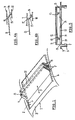
- Figure 1 shows perspectively and schematically part of a vehicle provided with an open roof assembly of the type to which the invention refers;
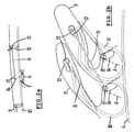
- Figure 2a shows, schematically, a longitudinal section through part of a prior art open roof assembly in a closed position;
- Figure 2b shows the same in an open position;
- Figure 3a shows, correspondingly, part of an inventive open roof assembly in the closed position;
- Figure 3b shows the same in an open position;
- Figure 4a and 4b show, schematically, different embodiments of the folding arm-extension arm assembly, and
- Figure 5 shows a view in longitudinal direction of part of an alternative embodiment.
-
- First we refer to figure 1, and a
vehicle 1 comprises aroof opening 2 defined in the roof 3 of the vehicle. A foldable closure means 4 is provided for opening and closing the roof opening 2 (as indicated schematically by arrow 5). Along the longitudinal edges of the roof opening 2guides 6 extend in which, in a driven manner, a number of spacedslides 7 are movable. Eachslide 7 carries anelongate folding arm 8 which, in a manner known per se, enables the closure means 4 to obtain a zig-zag like folded position when the closure means 4 is moved towards its open position. - It is noted, that in figure 1 only two folding
arms 8 are shown, but that, of course a larger number of foldingarms 8 may be provided. Further, it should be noted, that corresponding foldingarms 8 andslides 7 are provided at the opposite longitudinal edge of the closure means 4. Corresponding foldingarms 8 preferably will, moreover, be connected by primary supportingbeams 11 which, in a manner known per se, support the flexible closure means 4. - Although not shown in fig. 1, the closure means 4 comprises an
outer cloth 9 and aninner cloth 10 mutually spaced in the closed position of the closure means 4. The outer cloth, for example a tarpaulin, offers protection against the elements, wherein the inner cloth, for example, can be a headliner. - Now reference is made to fig. 2 which shows a prior art open roof assembly in its closed position (fig. 2a) and its open position (figure 2b).
- Referring to fig. 2a, in the closed position of the closure means 4 the
outer cloth 9 andinner cloth 10 are fully stretched. In this fully stretched position of theouter cloth 9 andinner cloth 10 the slides 7 (only one of which is shown) are positioned at some distance from each other. The foldingarms 8 extend substantially in the longitudinal direction of thevehicle 1. The end of eachfolding arm 8 remote from theslide 7 carries a primary support beam 11 (which, as mentioned before, is also carried by acorresponding folding arm 8 at the opposite longitudinal side of the closure means 4). Theprimary support beams 11 engage theupper cloth 9 and support it. Further aflexible loop 12 is positioned around thosesupport beams 11, whichflexible loop 12 is connected to theinner cloth 10. Like this the mentioned ends of the foldingarms 8 also support theinner cloth 10 via theflexible loop 12. The distance between theouter cloth 9 andinner cloth 10 basically will be determined by the length of theflexible loops 12. - The
slides 7 also are provided with supportingbeams 15 supporting theouter cloth 9 and supporting, by means of aflexible loop 16, theinner cloth 10. - When the closure means 4 is moved towards its open (or partially open) position, the
slides 7 are moved closer towards each other. As a result of the bias of thefolding arm 8 these will with their ends remote from theslides 7 move upwards (as indicated in fig. 2a), thus forming zig-zag like folds in the closure means 4. Two of such folds are illustrated in fig. 2b on a larger scale. Thefolding arms 8 now do not extend substantially in the longitudinal direction of the vehicle, but rather upwards or inclined upwards. Their ends remote from theslide 7 still support theouter cloth 9 via the primary support beams 11. Theinner cloth 10 still is connected to the folding arms 8 (or the support beams 11) via theflexible loops 12. However, because eachflexible loop 12 has a certain length (which, as shown in fig. 2a, determines the distance between theouter cloth 9 andinner cloth 10 in the closed position of the closure means 4), theinner cloth 10 will slide downwards (sag) somewhat relative to theouter cloth 9, such that the lowermost parts of theinner cloth 10 then are likely to engage neighbouring parts of the vehicle, such as a rear window, seals or alike. Such a situation is highly undesired, because it will cause stain and wear of theinner cloth 10. - Referring to fig. 3a and 3b, an open roof assembly according to the invention is illustrated in its closed position (fig. 3a) and its open position (fig. 3b). Firstly referring to fig. 3a, again a
slides 7 is visible (positioned at some distance from other slides not shown). Eachslide 7 carries abiased folding arm 8 which, with its end remote from theslide 7, supports the outer cloth 9 (in this case again by means of aprimary support beam 11 interconnecting correspondingfolding arms 8 at opposite longitudinal edges of the closure means 4). At its end remote from theslide 7 thefolding arm 8 is provided with anextension arm 13 extending in an inclined manner in a direction substantially away from thecorresponding slide 7 and towards theinner cloth 10. The end of thisextension arm 13 remote from thefolding arm 8 is connected to and substantially engages saidinner cloth 10 via a secondary supportingbeam 17. In the embodiment illustrated in fig. 3A a shortflexible loop 14 is provided which is connected to and supports theinner cloth 10 and which is positioned around the end of theextension arm 13 orsecondary support beam 17 interconnecting correspondingextension arms 13 at opposite longitudinal edges of the closure means 4. - Referring to fig. 3b, in its open (or partially open) position the closure means 4 will have a different position from what is shown in fig. 2b (prior art). Because now the rather long
flexible loop 12 according to the prior art is no longer provided, but instead theextension arm 13 connects to and substantially engages theinner cloth 10 with its end remote from the folding arm 8 (in this case, through the secondary supporting beam 17), theinner cloth 10 cannot slide downwards (sag) relative to theouter cloth 9, and therefore the lowermost parts of theinner cloth 10 will not engage neighbouring parts of the vehicle. Further, theextension arm 13 with its end (in this case the secondary supporting beam 17) also will engage the inside of the top of the fold of the outer cloth 9 (which, as shown in fig. 2b, is unsupported in the prior art solution). As a result the top of the fold of theouter cloth 9 will be wider and therefore much more tensioned. The aerodynamic flow over the folds will thus improve because the folds have a better shaped top. - Fig. 4a shows schematically a side elevational view of an embodiment of the assembly of folding
arm 8 andextension arm 13, in which theextension arm 13 has an angled configuration (firstly, theextension arm 13 extends beyond thefolding arm 8 aligned therewith and next, after a bend, inclined thereto), whereas fig. 4b shows an embodiment of the assembly of foldingarm 8 andextension arm 13, in which theextension arm 13 substantially has a straight configuration (it extends inclined directly beginning at said end of the folding arm 8). However, also other shapes are conceivable. Further it should be noted that theextension arm 13 can be a separate part attached in any appropriate manner to thefolding arm 8, but also can be an integral prolongation of thefolding arm 8. - Finally, figure 5 shows in a view in longitudinal direction the
inner cloth 10 andouter cloth 9, supported by the secondary support beam 17 (via flexible loops 14) and the primary supportingbeam 11, respectively. As can be seen, theextension arms 13 are staggered relative to thefolding arms 8, i.e. in transverse direction positioned between thefolding arms 8. The number ofextension arms 13 may vary; further the shape thereof may be different from what is shown. For example, the connection between the supportingbeams - The invention is not limited to the embodiments described before which may be varied widely within the scope of the invention as defined by the appending claims.
Claims (8)
- Open roof assembly for a vehicle, comprising a roof opening defined in the roof of the vehicle and a foldable closure means for closing and opening said roof opening, which closure means comprises an outer cloth and an inner cloth mutually spaced in the closed position of the closure means, wherein the closure means at its opposite longitudinal edges extending in the longitudinal direction of the vehicle is provided with a number of spaced slides which, in a driven manner, are movable along guides extending along corresponding longitudinal edges of the roof opening, and wherein the slides carry elongate folding arms that, with their end remote from the slides, support the outer cloth and inner cloth and that are biased towards a position for zig-zag like folding the closure means during opening the roof opening, characterized in that said end of the folding arms remote from the slides is provided with an extension arm extending in an inclined manner in a direction substantially away from the corresponding slide and towards the inner cloth, wherein the end of the extension arm remote from the folding arm is connected to and substantially engages the inner cloth.
- Open roof assembly according to claim 1, wherein the remote end of the extension arm engages a flexible loop attached to the inner cloth.
- Open roof assembly according to claim 1 or 2, wherein the extension arm is an integral prolongation of the folding arm.
- Open roof assembly according to any of the previous claims, wherein the extension arm has a straight configuration.
- Open roof assembly according to any of the claims 1-3, wherein the extension arm has an angled configuration.
- Open roof assembly according to any of the claims 1-5, wherein the said remote ends of corresponding folding arms at opposite longitudinal edges of the closure means are interconnected by outer cloth supporting beams extending transversaly to the longitudinal direction of the vehicle, and wherein the extension arms are connected to said supporting beams.
- Open roof assembly according to claim 6, wherein the said remote ends of corresponding extension arms are interconnected by inner cloth supporting beams extending transversaly to the longitudinal direction of the vehicle.
- Open roof assembly according to claim 7, wherein the extension arms are connected to said outer cloth supporting beams at transverse locations in between the folding arms.
Priority Applications (5)
| Application Number | Priority Date | Filing Date | Title |
|---|---|---|---|
| DE02080638T DE02080638T1 (en) | 2002-12-23 | 2002-12-23 | Openable roof construction for a vehicle |
| EP02080638A EP1433638B1 (en) | 2002-12-23 | 2002-12-23 | Open roof assembly for a vehicle |
| DE60218191T DE60218191T2 (en) | 2002-12-23 | 2002-12-23 | Openable roof construction for a vehicle |
| US10/744,313 US6918629B2 (en) | 2002-12-23 | 2003-12-22 | Open roof assembly for a vehicle |
| JP2003425820A JP2004203381A (en) | 2002-12-23 | 2003-12-22 | Vehicular open roof assembly |
Applications Claiming Priority (1)
| Application Number | Priority Date | Filing Date | Title |
|---|---|---|---|
| EP02080638A EP1433638B1 (en) | 2002-12-23 | 2002-12-23 | Open roof assembly for a vehicle |
Publications (2)
| Publication Number | Publication Date |
|---|---|
| EP1433638A1 true EP1433638A1 (en) | 2004-06-30 |
| EP1433638B1 EP1433638B1 (en) | 2007-02-14 |
Family
ID=32405766
Family Applications (1)
| Application Number | Title | Priority Date | Filing Date |
|---|---|---|---|
| EP02080638A Expired - Lifetime EP1433638B1 (en) | 2002-12-23 | 2002-12-23 | Open roof assembly for a vehicle |
Country Status (4)
| Country | Link |
|---|---|
| US (1) | US6918629B2 (en) |
| EP (1) | EP1433638B1 (en) |
| JP (1) | JP2004203381A (en) |
| DE (2) | DE60218191T2 (en) |
Families Citing this family (4)
| Publication number | Priority date | Publication date | Assignee | Title |
|---|---|---|---|---|
| EP1676736B1 (en) * | 2004-12-30 | 2009-09-30 | Grupo Antolin-Ingenieria, S.A. | Sunshade for vehicle roofs having a transparent element |
| US7416247B2 (en) * | 2006-12-15 | 2008-08-26 | Chrysler Llc | Retractable vehicle roof system |
| US7938483B2 (en) * | 2007-05-24 | 2011-05-10 | Specialty Vehicle Acquisition Corp. | Movable vehicular roof |
| KR20150069262A (en) * | 2013-12-13 | 2015-06-23 | 현대자동차주식회사 | Apparatus for preventing droop of blind for panorama sunroof |
Citations (5)
| Publication number | Priority date | Publication date | Assignee | Title |
|---|---|---|---|---|
| DE4319718C1 (en) * | 1993-06-15 | 1994-08-18 | Webasto Karosseriesysteme | Folding roof for vehicles |
| DE4411387A1 (en) * | 1993-03-31 | 1994-10-06 | Webasto Karosseriesysteme | Openable vehicle roof |
| DE19647730C1 (en) * | 1996-11-19 | 1998-05-20 | Webasto Karosseriesysteme | Folding sunroof for automobile |
| FR2786441A1 (en) * | 1998-12-01 | 2000-06-02 | Peugeot | Vehicle roof has series of transverse rigid panels hinged by sections of a connecting membrane with shoes on the edges of alternate hinges that slide in guide rails at the sides of the roof |
| DE19929324C1 (en) * | 1999-06-26 | 2000-06-29 | Cts Fahrzeug Dachsysteme Gmbh | Opening roof system for vehicles has two or more adjoining roof elements with folding outer skin of water-repellent material spanned over same |
Family Cites Families (3)
| Publication number | Priority date | Publication date | Assignee | Title |
|---|---|---|---|---|
| JPS63103733A (en) * | 1986-10-20 | 1988-05-09 | Mazda Motor Corp | Canvas top structure of vehicle |
| JPH0445127U (en) * | 1990-08-20 | 1992-04-16 | ||
| DE4318718C2 (en) | 1993-06-07 | 1997-07-03 | Kalloy Ind Co | Bicycle seat adjustment arrangement |
-
2002
- 2002-12-23 DE DE60218191T patent/DE60218191T2/en not_active Expired - Lifetime
- 2002-12-23 DE DE02080638T patent/DE02080638T1/en active Pending
- 2002-12-23 EP EP02080638A patent/EP1433638B1/en not_active Expired - Lifetime
-
2003
- 2003-12-22 US US10/744,313 patent/US6918629B2/en not_active Expired - Lifetime
- 2003-12-22 JP JP2003425820A patent/JP2004203381A/en active Pending
Patent Citations (5)
| Publication number | Priority date | Publication date | Assignee | Title |
|---|---|---|---|---|
| DE4411387A1 (en) * | 1993-03-31 | 1994-10-06 | Webasto Karosseriesysteme | Openable vehicle roof |
| DE4319718C1 (en) * | 1993-06-15 | 1994-08-18 | Webasto Karosseriesysteme | Folding roof for vehicles |
| DE19647730C1 (en) * | 1996-11-19 | 1998-05-20 | Webasto Karosseriesysteme | Folding sunroof for automobile |
| FR2786441A1 (en) * | 1998-12-01 | 2000-06-02 | Peugeot | Vehicle roof has series of transverse rigid panels hinged by sections of a connecting membrane with shoes on the edges of alternate hinges that slide in guide rails at the sides of the roof |
| DE19929324C1 (en) * | 1999-06-26 | 2000-06-29 | Cts Fahrzeug Dachsysteme Gmbh | Opening roof system for vehicles has two or more adjoining roof elements with folding outer skin of water-repellent material spanned over same |
Also Published As
| Publication number | Publication date |
|---|---|
| DE02080638T1 (en) | 2005-03-31 |
| JP2004203381A (en) | 2004-07-22 |
| US6918629B2 (en) | 2005-07-19 |
| US20040135404A1 (en) | 2004-07-15 |
| DE60218191D1 (en) | 2007-03-29 |
| EP1433638B1 (en) | 2007-02-14 |
| DE60218191T2 (en) | 2007-10-18 |
Similar Documents
| Publication | Publication Date | Title |
|---|---|---|
| US8292360B2 (en) | Deflector device for a sunroof device | |
| US6874845B2 (en) | Shade tarp as sun shield | |
| US20060040607A1 (en) | Adjustable pergola | |
| US5341864A (en) | Adjustable expandable and collapsible shade | |
| SE454864B (en) | INFALLABLE REAR WINDOW CONSTRUCTION FOR A VEHICLE | |
| JPH02231227A (en) | Hood cloth for folding hood of vehicle | |
| US4565230A (en) | Movable curtain systems for greenhouses and components therefor | |
| US20080067839A1 (en) | Wind Deflector | |
| US7152917B2 (en) | Wind deflector and open roof construction provided therewith | |
| EP1433638B1 (en) | Open roof assembly for a vehicle | |
| US20030155794A1 (en) | Roof device for a vehicle | |
| US20090309393A1 (en) | Wind deflector | |
| CN104428150B (en) | Sliding top skylight for motor vehicle | |
| EP0240065A1 (en) | Folding curtain screen structure for a triangular window | |
| CN102649392B (en) | Sunshade and be provided with the Open roof construction of described sunshade | |
| EP2674312B1 (en) | Openable roof system for a vehicle | |
| WO2010088955A1 (en) | Sunshade assembly | |
| US4798410A (en) | Lifting sliding roof for vehicles | |
| US5887636A (en) | Venetian blind | |
| US7156445B2 (en) | Sealing mechanism for convertible top of vehicle | |
| EP1676736B1 (en) | Sunshade for vehicle roofs having a transparent element | |
| CN114585529B (en) | Flow guiding mechanism of skylight device | |
| EP1027822A2 (en) | Retractable roof structure | |
| NL1043950B1 (en) | SCREEN EQUIPMENT AND GREENHOUSE IN WHICH IT IS APPLIED | |
| JP2892118B2 (en) | Cover type sunroof device |
Legal Events
| Date | Code | Title | Description |
|---|---|---|---|
| PUAI | Public reference made under article 153(3) epc to a published international application that has entered the european phase |
Free format text: ORIGINAL CODE: 0009012 |
|
| AK | Designated contracting states |
Kind code of ref document: A1 Designated state(s): AT BE BG CH CY CZ DE DK EE ES FI FR GB GR IE IT LI LU MC NL PT SE SI SK TR |
|
| AX | Request for extension of the european patent |
Extension state: AL LT LV MK RO |
|
| EL | Fr: translation of claims filed | ||
| 17P | Request for examination filed |
Effective date: 20041119 |
|
| AKX | Designation fees paid |
Designated state(s): DE FR GB |
|
| DET | De: translation of patent claims | ||
| RBV | Designated contracting states (corrected) |
Designated state(s): DE FR GB |
|
| GRAP | Despatch of communication of intention to grant a patent |
Free format text: ORIGINAL CODE: EPIDOSNIGR1 |
|
| GRAC | Information related to communication of intention to grant a patent modified |
Free format text: ORIGINAL CODE: EPIDOSCIGR1 |
|
| GRAS | Grant fee paid |
Free format text: ORIGINAL CODE: EPIDOSNIGR3 |
|
| GRAA | (expected) grant |
Free format text: ORIGINAL CODE: 0009210 |
|
| AK | Designated contracting states |
Kind code of ref document: B1 Designated state(s): DE FR GB |
|
| REG | Reference to a national code |
Ref country code: GB Ref legal event code: FG4D |
|
| REF | Corresponds to: |
Ref document number: 60218191 Country of ref document: DE Date of ref document: 20070329 Kind code of ref document: P |
|
| ET | Fr: translation filed | ||
| PLBE | No opposition filed within time limit |
Free format text: ORIGINAL CODE: 0009261 |
|
| STAA | Information on the status of an ep patent application or granted ep patent |
Free format text: STATUS: NO OPPOSITION FILED WITHIN TIME LIMIT |
|
| 26N | No opposition filed |
Effective date: 20071115 |
|
| PGFP | Annual fee paid to national office [announced via postgrant information from national office to epo] |
Ref country code: GB Payment date: 20071219 Year of fee payment: 6 |
|
| GBPC | Gb: european patent ceased through non-payment of renewal fee |
Effective date: 20081223 |
|
| PG25 | Lapsed in a contracting state [announced via postgrant information from national office to epo] |
Ref country code: GB Free format text: LAPSE BECAUSE OF NON-PAYMENT OF DUE FEES Effective date: 20081223 |
|
| PGFP | Annual fee paid to national office [announced via postgrant information from national office to epo] |
Ref country code: FR Payment date: 20131231 Year of fee payment: 12 |
|
| REG | Reference to a national code |
Ref country code: FR Ref legal event code: ST Effective date: 20150831 |
|
| PG25 | Lapsed in a contracting state [announced via postgrant information from national office to epo] |
Ref country code: FR Free format text: LAPSE BECAUSE OF NON-PAYMENT OF DUE FEES Effective date: 20141231 |
|
| PGFP | Annual fee paid to national office [announced via postgrant information from national office to epo] |
Ref country code: DE Payment date: 20201229 Year of fee payment: 19 |
|
| REG | Reference to a national code |
Ref country code: DE Ref legal event code: R119 Ref document number: 60218191 Country of ref document: DE |
|
| PG25 | Lapsed in a contracting state [announced via postgrant information from national office to epo] |
Ref country code: DE Free format text: LAPSE BECAUSE OF NON-PAYMENT OF DUE FEES Effective date: 20220701 |