EP1433557A2 - Method and apparatus for near net shape rapid rough machining for blisks - Google Patents
Method and apparatus for near net shape rapid rough machining for blisks Download PDFInfo
- Publication number
- EP1433557A2 EP1433557A2 EP03258106A EP03258106A EP1433557A2 EP 1433557 A2 EP1433557 A2 EP 1433557A2 EP 03258106 A EP03258106 A EP 03258106A EP 03258106 A EP03258106 A EP 03258106A EP 1433557 A2 EP1433557 A2 EP 1433557A2
- Authority
- EP
- European Patent Office
- Prior art keywords
- cutting element
- annular cutting
- arrangement
- blisk
- set forth
- Prior art date
- Legal status (The legal status is an assumption and is not a legal conclusion. Google has not performed a legal analysis and makes no representation as to the accuracy of the status listed.)
- Granted
Links
Images

Classifications
-
- B—PERFORMING OPERATIONS; TRANSPORTING
- B23—MACHINE TOOLS; METAL-WORKING NOT OTHERWISE PROVIDED FOR
- B23H—WORKING OF METAL BY THE ACTION OF A HIGH CONCENTRATION OF ELECTRIC CURRENT ON A WORKPIECE USING AN ELECTRODE WHICH TAKES THE PLACE OF A TOOL; SUCH WORKING COMBINED WITH OTHER FORMS OF WORKING OF METAL
- B23H9/00—Machining specially adapted for treating particular metal objects or for obtaining special effects or results on metal objects
- B23H9/10—Working turbine blades or nozzles
-
- B—PERFORMING OPERATIONS; TRANSPORTING
- B23—MACHINE TOOLS; METAL-WORKING NOT OTHERWISE PROVIDED FOR
- B23H—WORKING OF METAL BY THE ACTION OF A HIGH CONCENTRATION OF ELECTRIC CURRENT ON A WORKPIECE USING AN ELECTRODE WHICH TAKES THE PLACE OF A TOOL; SUCH WORKING COMBINED WITH OTHER FORMS OF WORKING OF METAL
- B23H3/00—Electrochemical machining, i.e. removing metal by passing current between an electrode and a workpiece in the presence of an electrolyte
Definitions
- the present invention relates generally to an electromachining method and more specifically to an arrangement which can be used to rough machine the airfoils on bladed disks (or so-called blisks) to a near net shape at a high metal removal rate and with a low tooling cost as compared to turning, milling, EDM (electrodischarge machining) or ECM (electrochemical machining).
- the electromachining is a technique which utilizes the rotating movement of a profile ⁇ shaped electrode to remove material from a work piece by controlled electrical erosion.
- the kinematics of the machining is analogous to milling or grinding.
- the tool-electrode is connected to the negative polarity, while the workpiece is connected to the positive polarity of a pulse generator or continuous power supply of direct current.
- a gap between the electrodes allows for the flow of an electrolyte.
- the electrical erosion can be created by electrical breakdown of the electrolyte or vapor-gas layer produced at the machining interface, as well as by instantaneous arcing or transient short-circuits between the electrodes.
- the deciding factor is the electrical current and duration of the erosion process.
- the electrical erosion of the machining surface is relatively course and a large number of craters are formed in the erosion zone. Thus, this technique cannot be used to produce finely machined work pieces.
- a first aspect of the invention resides in an arrangement for machining airfoils on a blisk, comprising: an annular cutting element supported for rotation about an axis of rotation and adapted for the electromachining.
- a second aspect of the invention resides in a method of machining airfoils on a blisk, comprising the steps of: driving an annular cutting element to rotate about its axis; supplying the annular cutting element with a supply of electricity; supplying electrolyte to the interelectrode gap between the annular cutting element and; moving the annular cutting element in multiple mutually opposed directions using a programmable control arrangement to erode material from a work piece to form the blisk.
- a third aspect of the invention resides in an arrangement for machining airfoils on a blisk, comprising: means for driving an annular cutting element to rotate about its axis; means for supplying the annular cutting element with a supply of electricity; means for supplying the interelectrode gap with a supply of fluid; and means for moving the annular cutting element in multiple mutually opposed directions using a programmable control arrangement to erode material from a work piece to form the blisk.
- the present invention is directed to obviating machining difficulties associated with the manufacture of components such as bladed discs and complex structures.
- Aircraft engines and industrial gas turbines have traditionally used bladed compressor disks with individual airfoils anchored by nuts and bolts in a slotted central retainer. To reduce aerodynamic losses, weight, and complexity in the engine, these disk assemblies have been replaced with a one-piece bladed disk, which is referred to as a "blisk”.
- blisk can replace up to 120 parts or more in an engine.
- blisks are difficult to machine.
- the workpiece typically begins as a circular disk. Material is removed in such a fashion to form a pocket between the concave and convex surfaces on two adjacent airfoils. This process is repeated until all pockets have been completed and the remaining material defines the preform airfoils and the remainder of the blisk.
- the disclosed embodiments of the invention are directed to reducing the difficulty and improving the efficiency with which blisks and the like can be manufactured.
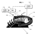
- the cutting tool generally denoted by the numeral 100 comprises a circular ring or ring tool 102 made of a suitable electrically conductive material such as mild steel.
- This ring tool 102 is rotatably supported on an essentially C-shaped support plate 104 by way of a plurality of guide roller sets 106.
- the thickness, width, and diameter of the ring tool 102 are selected such that it will machine the pockets in such a manner that the remaining material (preform airfoils) are close to net shape with some thickness allowance left over for finishing, and without gouging into the finished shape of the preform.
- the shape of the support plate is not limited to the illustrated configuration and can be adapted depending on the machining task to which the arrangement is being applied.
- the cutting tool 100 is supported and positionally controlled through the use of a support/translation arrangement 108 which may be a commercially available arrangement and which enables movement along a number of axes of motion, such as 4 axes of motion.
- This support/translation arrangement 108 preferably includes a Computer Numerical Controlled (CNC) drive and control. Control of motion along the X, Y and Z axes is achieved with this arrangement which enables the feedrate in Z-axis to be programmed and controlled.
- the X and Y translation can also be programmed, controlled and interpolated. This is to enable either the inner diameter (ID) or the outer diameter (OD) of the tool ring to be cut as close to the airfoil sectional profile as possible, leaving some finishing allowance.
- Additional axes of motion may be imparted to the workpiece, if this will assist in the machining process.
- the cutting tool is annular, and therefore has a central, circular opening, it can be maneuvered to positions with respect to the work piece which would not be possible with a flat non-perforate disc type cutting element for example.
- Rotation of the ring tool 102 in the direction indicated by W is used to provide a cutting action relative to the stationary circular slab, blank or work piece.
- translation along the Z axis of the ring is used to provide down feeding while cutting a slot on the circular slab in between two airfoils of the blisk.
- Positional adjustment along the X and Y axes is used to enable the required curvature of the airfoils to be roughed out.
- the rotation of tool ring 102 is provided from a drive source 110 which includes a source of rotational energy and which can incorporate a transmission.
- the rotary source can be an electric motor with a speed control.
- the transmission can be a gearing such as a step-down gearing, a belt or other means to transmit the rotational motion from the source to the cutting tool.
- the rotational speed of the ring tool 102 which determines the cutting surface speed, can be set and controlled to the appropriate level by using one or both of the motor speed control and transmission, which can be provided with a variable speed gearing, if preferred.
- the first embodiment further includes a power supply unit 112 which provides a supply of electricity suitable for the electromachining cutting, to the ring tool 102.
- the transfer of electricity to the rotating ring 102 can be achieved through a brush system or conductive roller arrangement 114.
- Shallow slots 102S can be cut into the cutting face of the ring tool 102 so as to avoid continuous arcing during the electromachining cutting process.
- a cutting zone is exposed so that cutting fluid can be readily fed into it from a fluid supply 116.
- This fluid supply includes a pump or the like for inducing a flow of fluid.
- This fluid can be water, de-ionized water or an aqueous electrolyte solution, dispersion, or mixture of suitable electrolytic substances/liquids or the like.
- solutions of NaNO 2 , NaOH, or mixtures of Na 2 CO 3 and NaNO 2 can be used.
- internal passages can be provided in/on the ring tool 102 (see delivery ports 102P associated with this passage structure in Fig. 3) to delivery cutting fluid in sufficient quantities to the cutting zone.
- a second embodiment of the invention uses an inverted circular cup (viz., a hollow frusto-conical configuration) 202.
- a drive arrangement having a motor and/transmission, such as disclosed above, is arranged in drive connection with an upper end of the cup.
- the open end (lip) of the cup is in effect an annular member and acts as the ring cutter disclosed above in connection with the first embodiment (Fig. 1).
Landscapes
- Engineering & Computer Science (AREA)
- Mechanical Engineering (AREA)
- Chemical & Material Sciences (AREA)
- Chemical Kinetics & Catalysis (AREA)
- Electrochemistry (AREA)
- Physics & Mathematics (AREA)
- Thermal Sciences (AREA)
- Electrical Discharge Machining, Electrochemical Machining, And Combined Machining (AREA)
- Structures Of Non-Positive Displacement Pumps (AREA)
- Milling Processes (AREA)
Abstract
Description
Claims (10)
- An arrangement for machining airfoils on a blisk, comprisingan annular cutting element (102, 202) supported for rotation about an axis of rotation and adapted for the electromachining process.
- An arrangement as set forth in claim 1, wherein the annular cutting element comprises an annular lip of an inverted cup-shaped member (202).
- An arrangement as set forth in claim 1, further comprising:a support and translation device (108) for supporting the annular cutting element and for moving the annular cutting element along at least three mutually opposed axes;a drive (110) operatively connected with the annular cutting element (102, 202) to drive the annular cutting element (102) to rotate about the axis of rotation; anda power supply (112) operatively connected with the annular cutting element.
- An arrangement as set forth in claim 4, further comprising a fluid supply (116) providing fluid to the annular cutting element.
- An arrangement as set forth in claim 4, wherein the fluid supply comprises a passage structure in the annular cutting element which passage structure is adapted to direct fluid into a cutting zone.
- An arrangement as set forth in claim 1, wherein the annular cutting element is supported on a shaped support plate (104) and supported so as to be rotatable with respect thereto by a plurality of rollers (106)
- An arrangement as set forth in claim 1, wherein the annular cutting element is formed with shallow slots (102S) adapted to prevent continuous arcing between the annular cutting element and a work piece being cut by the annular cutting element.
- A method of machining airfoils on a blisk, comprising the steps of:driving an annular cutting element (102) to rotate about its axis;supplying the annular cutting element (102) with a supply of electricity;supplying the annular cutting element (102) with a supply of fluid;moving the annular cutting element (102) in three mutually opposed directions using a programmable control arrangement to erode material from a work piece to form the blisk.
- An arrangement for machining airfoils on a blisk, comprising:means (110, 106) for driving an annular cutting element to rotate about its axis;means (112, 114) for supplying the annular cutting element with a supply of electricity;means (116) for supplying the annular cutting element with a supply of fluid; andmeans (108) for moving the annular cutting element in three mutually opposed directions using a programmable control arrangement to erode material from a work piece to form the blisk.
- An arrangement as set forth in claim 9, further comprising shallow slots (102S) formed in the annular cutting element to prevent continuous arcing between the annular cutting element and the work piece.
Applications Claiming Priority (2)
| Application Number | Priority Date | Filing Date | Title |
|---|---|---|---|
| US10/248,215 US6787728B2 (en) | 2002-12-27 | 2002-12-27 | Method and apparatus for near net shape rapid rough electromachining for blisks |
| US248215 | 2002-12-27 |
Publications (3)
| Publication Number | Publication Date |
|---|---|
| EP1433557A2 true EP1433557A2 (en) | 2004-06-30 |
| EP1433557A3 EP1433557A3 (en) | 2005-02-02 |
| EP1433557B1 EP1433557B1 (en) | 2008-06-11 |
Family
ID=32467676
Family Applications (1)
| Application Number | Title | Priority Date | Filing Date |
|---|---|---|---|
| EP03258106A Expired - Lifetime EP1433557B1 (en) | 2002-12-27 | 2003-12-22 | Apparatus for near net shape rapid rough machining for blisks |
Country Status (5)
| Country | Link |
|---|---|
| US (1) | US6787728B2 (en) |
| EP (1) | EP1433557B1 (en) |
| JP (1) | JP4906229B2 (en) |
| CN (1) | CN100448583C (en) |
| DE (1) | DE60321532D1 (en) |
Cited By (10)
| Publication number | Priority date | Publication date | Assignee | Title |
|---|---|---|---|---|
| WO2006027608A1 (en) | 2004-09-09 | 2006-03-16 | Bladon Jets Limited | Fans and turbines |
| DE102005014642A1 (en) * | 2005-03-31 | 2006-10-05 | Leybold Vacuum Gmbh | Electrodischarge machining device in particular for creation of rotor disk for turbomolecular pump comprising tool designed as triangular loop |
| DE102007022467A1 (en) * | 2007-05-08 | 2008-11-13 | Rolls-Royce Deutschland Ltd & Co Kg | Method and device for blade tip grinding of a trained in BLISK design impeller |
| FR2929152A1 (en) * | 2008-03-31 | 2009-10-02 | Snecma Sa | IMPROVED METHOD FOR MANUFACTURING A MONOBLOC AUBING DISK, WITH PROVISIONAL RING FOR MAINTAINING AUBES REMOVED AFTER A MILLING FINISHING STEP |
| FR2929151A1 (en) * | 2008-03-31 | 2009-10-02 | Snecma Sa | IMPROVED PROCESS FOR MANUFACTURING A MONOBLOC AUBING DISC, WITH PROVISIONAL RING FOR MAINTAINING THE BLADES REMOVED BEFORE A MILLING STEP |
| FR2929150A1 (en) * | 2008-03-31 | 2009-10-02 | Snecma Sa | IMPROVED PROCESS FOR MANUFACTURING A MONOBLOC AUBING DISC, WITH PROVISIONAL RING FOR MAINTAINING AUBES |
| FR2929154A1 (en) * | 2008-03-31 | 2009-10-02 | Snecma Sa | IMPROVED METHOD FOR MANUFACTURING A MONOBLOC AUBING DISK, WITH PROVISIONAL RETAINING RING FOR REMOVED BLADES BEFORE A MILLING FINISHING STEP |
| FR2929155A1 (en) * | 2008-03-31 | 2009-10-02 | Snecma Sa | IMPROVED PROCESS FOR MANUFACTURING A MONOBLOC AUBING DISC, WITH PROVISIONAL RING FOR MAINTAINING AUBES REMOTE AGENCY FROM THEIR HEAD |
| GB2467523A (en) * | 2009-01-30 | 2010-08-04 | Cummins Turbo Tech Ltd | Method for manufacturing turbine wheels |
| US8127444B2 (en) | 2003-02-26 | 2012-03-06 | Christopher George Bladon | Fans and turbines |
Families Citing this family (22)
| Publication number | Priority date | Publication date | Assignee | Title |
|---|---|---|---|---|
| US20050247569A1 (en) * | 2004-05-07 | 2005-11-10 | Lamphere Michael S | Distributed arc electroerosion |
| CN100362225C (en) * | 2005-06-30 | 2008-01-16 | 北京航空航天大学 | Miniature single impeller turbofan engine |
| US7394040B2 (en) * | 2006-03-31 | 2008-07-01 | General Electric Company | Electromachining process and apparatus |
| US8161641B2 (en) * | 2006-07-19 | 2012-04-24 | General Electric Company | Compound electromachining |
| CN100450686C (en) * | 2006-10-19 | 2009-01-14 | 杨龙兴 | Wire electrode cutting process of steam turbine blade |
| US7741576B2 (en) * | 2007-05-11 | 2010-06-22 | General Electric Company | Apparatus and method for hybrid machining a workpiece |
| US7976694B2 (en) * | 2007-07-17 | 2011-07-12 | General Electric Company | Apparatus and method for hybrid machining a contoured, thin-walled workpiece |
| JP5301125B2 (en) * | 2007-08-03 | 2013-09-25 | ゼネラル・エレクトリック・カンパニイ | Combined electromachining method |
| DE102008017494A1 (en) * | 2008-04-04 | 2009-10-08 | Rolls-Royce Deutschland Ltd & Co Kg | Method for manufacturing integrally bladed rotors |
| US9333577B2 (en) * | 2008-08-29 | 2016-05-10 | General Electric Company | Electro discharge machining apparatus and method |
| US20100163427A1 (en) * | 2008-12-31 | 2010-07-01 | Yimin Zhan | Methods and systems for electromachining of a workpiece |
| IT1396512B1 (en) | 2009-10-21 | 2012-12-14 | Nuovo Pignone Spa | METHOD AND DEVICE FOR TOOL COMPENSATION |
| CN102728915B (en) * | 2012-07-03 | 2014-05-07 | 北京航空航天大学 | Synchronous numerical control machining method and device applicable to curved surface structure uniformly distributed along peripheral direction |
| CN103521861B (en) * | 2013-09-29 | 2015-10-28 | 南京航空航天大学 | Based on blisk profile electrolytic machining device and the method for three-dimensional complex wake |
| CN103624350B (en) * | 2013-11-21 | 2017-01-04 | 南京航空航天大学 | A kind of integrated impeller blade electrolysis polish forming device and integrated impeller blade thereof shape method |
| FR3015554B1 (en) * | 2013-12-19 | 2016-01-29 | Snecma | TURBINE RING SECTOR FOR AIRCRAFT TURBOMACHINE HAVING IMPROVED GRIPPING PORTS |
| JP6633344B2 (en) | 2015-10-21 | 2020-01-22 | 株式会社Ihi | Blisk manufacturing method |
| JP6747946B2 (en) * | 2016-11-25 | 2020-08-26 | 三菱日立パワーシステムズ株式会社 | Electric discharge machining method and electric discharge machine |
| CN111037014B (en) * | 2019-11-22 | 2021-02-26 | 南京航空航天大学 | Nesting electrochemical machining device and method for inward blades of multistage rectifying stator |
| CN113618176B (en) * | 2021-08-13 | 2022-08-30 | 合肥工业大学 | Electromagnetic control type blisk electrolytic machining device and method |
| CN113814492B (en) * | 2021-10-26 | 2022-07-29 | 南京航浦机械科技有限公司 | Closed blisk runner electrolytic machining device and method |
| CN117020959B (en) * | 2023-10-09 | 2025-10-10 | 中国航发沈阳黎明航空发动机有限责任公司 | An integrated forming method for processing an integral blade disk |
Family Cites Families (13)
| Publication number | Priority date | Publication date | Assignee | Title |
|---|---|---|---|---|
| US3642601A (en) * | 1968-12-03 | 1972-02-15 | Iwao Kondo | Machine for processing a piece of work by electric current |
| JPS58171221A (en) * | 1982-04-02 | 1983-10-07 | Hitachi Seiko Ltd | Electrode contour machining by numerically controlled electric discharge machine |
| DE3507274A1 (en) * | 1985-03-01 | 1986-09-04 | Arthur Pfeiffer Vakuumtechnik Wetzlar Gmbh, 6334 Asslar | DISC WITH SHOVELS HIGH STABILITY FOR TURBOMOLECULAR PUMPS |
| JPH0392268A (en) * | 1989-08-31 | 1991-04-17 | Olympus Optical Co Ltd | Electro-chemical machining for optical element and its equipment |
| CN2088917U (en) * | 1991-01-29 | 1991-11-20 | 机电部北京机电研究所 | Electrode with complex structure for gear shaped element |
| US5313038A (en) * | 1992-12-22 | 1994-05-17 | United Technologies Corporation | EDM drilling of low angle holes |
| US5893984A (en) * | 1995-10-27 | 1999-04-13 | General Electric Company | High aspect ratio EDM electrode assembly |
| US5861608A (en) * | 1996-11-07 | 1999-01-19 | Ico, Inc. | EDM cutting machine for precision notching tubulars |
| US6162347A (en) * | 1998-09-28 | 2000-12-19 | General Electric Company | Co-machined bonded airfoil |
| US6156188A (en) * | 1999-06-21 | 2000-12-05 | Industrial Technology Research Institute | Method for making a probe device having detective function |
| TW424029B (en) * | 1999-08-06 | 2001-03-01 | Nat Science Council | An electropolishing method using a tool electrode with hollow appearance and its apparatus thereof |
| JP2001062633A (en) * | 1999-08-26 | 2001-03-13 | Minebea Co Ltd | Curved surface machining method and device |
| US6562227B2 (en) * | 2001-07-31 | 2003-05-13 | General Electric Company | Plunge electromachining |
-
2002
- 2002-12-27 US US10/248,215 patent/US6787728B2/en not_active Expired - Lifetime
-
2003
- 2003-12-22 DE DE60321532T patent/DE60321532D1/en not_active Expired - Lifetime
- 2003-12-22 EP EP03258106A patent/EP1433557B1/en not_active Expired - Lifetime
- 2003-12-26 JP JP2003432090A patent/JP4906229B2/en not_active Expired - Lifetime
- 2003-12-27 CN CNB2003101147202A patent/CN100448583C/en not_active Expired - Lifetime
Cited By (23)
| Publication number | Priority date | Publication date | Assignee | Title |
|---|---|---|---|---|
| US8127444B2 (en) | 2003-02-26 | 2012-03-06 | Christopher George Bladon | Fans and turbines |
| US8091230B2 (en) | 2004-09-09 | 2012-01-10 | Bladon Jets Limited | Method and apparatus for the manufacture of fans, turbines and guide vanes |
| WO2006027608A1 (en) | 2004-09-09 | 2006-03-16 | Bladon Jets Limited | Fans and turbines |
| CN101052490B (en) * | 2004-09-09 | 2011-12-28 | 布莱德捷斯有限公司 | Processing method, process, equipment of blade, and product containing the blades |
| DE102005014642A1 (en) * | 2005-03-31 | 2006-10-05 | Leybold Vacuum Gmbh | Electrodischarge machining device in particular for creation of rotor disk for turbomolecular pump comprising tool designed as triangular loop |
| US7833086B2 (en) | 2007-05-08 | 2010-11-16 | Rolls-Royce Deutschland Ltd & Co Kg | Method and apparatus for grinding the blade tips of a rotor wheel in BLISK design |
| DE102007022467A1 (en) * | 2007-05-08 | 2008-11-13 | Rolls-Royce Deutschland Ltd & Co Kg | Method and device for blade tip grinding of a trained in BLISK design impeller |
| FR2929150A1 (en) * | 2008-03-31 | 2009-10-02 | Snecma Sa | IMPROVED PROCESS FOR MANUFACTURING A MONOBLOC AUBING DISC, WITH PROVISIONAL RING FOR MAINTAINING AUBES |
| FR2929155A1 (en) * | 2008-03-31 | 2009-10-02 | Snecma Sa | IMPROVED PROCESS FOR MANUFACTURING A MONOBLOC AUBING DISC, WITH PROVISIONAL RING FOR MAINTAINING AUBES REMOTE AGENCY FROM THEIR HEAD |
| WO2009121762A1 (en) * | 2008-03-31 | 2009-10-08 | Snecma | Improved method for making a one-piece bladed disk, with temporary retaining ring for bladed disks removed before a milling step |
| WO2009121768A1 (en) * | 2008-03-31 | 2009-10-08 | Snecma | Improved method for producing a one-piece bladed disc, with temporary blade-supporting ring which is removed after a finish-milling step |
| WO2009121764A1 (en) * | 2008-03-31 | 2009-10-08 | Snecma | Improved method for producing a one-piece bladed disc, with temporary blade-supporting ring |
| WO2009121766A1 (en) * | 2008-03-31 | 2009-10-08 | Snecma | Improved method for producing a one-piece bladed disc, with temporary blade-supporting ring at a distance from their tips |
| US8505202B2 (en) | 2008-03-31 | 2013-08-13 | Snecma | Process for manufacturing a single-piece blisk with a temporary blade support ring arranged at a distance from blade tips |
| WO2009121765A1 (en) * | 2008-03-31 | 2009-10-08 | Snecma | Improved method for producing a one-piece bladed disc, with temporary blade-supporting ring which is removed before a finish-milling step |
| FR2929154A1 (en) * | 2008-03-31 | 2009-10-02 | Snecma Sa | IMPROVED METHOD FOR MANUFACTURING A MONOBLOC AUBING DISK, WITH PROVISIONAL RETAINING RING FOR REMOVED BLADES BEFORE A MILLING FINISHING STEP |
| FR2929151A1 (en) * | 2008-03-31 | 2009-10-02 | Snecma Sa | IMPROVED PROCESS FOR MANUFACTURING A MONOBLOC AUBING DISC, WITH PROVISIONAL RING FOR MAINTAINING THE BLADES REMOVED BEFORE A MILLING STEP |
| FR2929152A1 (en) * | 2008-03-31 | 2009-10-02 | Snecma Sa | IMPROVED METHOD FOR MANUFACTURING A MONOBLOC AUBING DISK, WITH PROVISIONAL RING FOR MAINTAINING AUBES REMOVED AFTER A MILLING FINISHING STEP |
| US8375583B2 (en) | 2008-03-31 | 2013-02-19 | Snecma | Process for manufacturing a single-piece blisk with a temporary blade support ring removed before a milling finishing step |
| US8429817B2 (en) | 2008-03-31 | 2013-04-30 | Snecma | Process for manufacturing a single-piece blisk with a temporary blade support ring removed after a milling finishing step |
| US8434224B2 (en) | 2008-03-31 | 2013-05-07 | Snecma | Method for manufacture of an integrally bladed rotor, with temporary blade-holding ring |
| US8464425B2 (en) | 2008-03-31 | 2013-06-18 | Snecma | Process for manufacturing a single-piece blisk with a temporary blade support ring removed before a milling step |
| GB2467523A (en) * | 2009-01-30 | 2010-08-04 | Cummins Turbo Tech Ltd | Method for manufacturing turbine wheels |
Also Published As
| Publication number | Publication date |
|---|---|
| CN100448583C (en) | 2009-01-07 |
| DE60321532D1 (en) | 2008-07-24 |
| US20040124181A1 (en) | 2004-07-01 |
| CN1511667A (en) | 2004-07-14 |
| EP1433557B1 (en) | 2008-06-11 |
| JP2004209639A (en) | 2004-07-29 |
| JP4906229B2 (en) | 2012-03-28 |
| US6787728B2 (en) | 2004-09-07 |
| EP1433557A3 (en) | 2005-02-02 |
Similar Documents
| Publication | Publication Date | Title |
|---|---|---|
| EP1433557B1 (en) | Apparatus for near net shape rapid rough machining for blisks | |
| EP2170546B1 (en) | Apparatus and method for hybrid machining a contoured, thin-walled workpiece | |
| JP5789070B2 (en) | Distributed arc electric corrosion | |
| US6562227B2 (en) | Plunge electromachining | |
| US7741576B2 (en) | Apparatus and method for hybrid machining a workpiece | |
| US6858125B2 (en) | Multi-axis numerical control electromachining of bladed disks | |
| US8161641B2 (en) | Compound electromachining | |
| RU2535820C2 (en) | Device for electric pulse machining | |
| CN114985854B (en) | Electrolytic-micro milling composite ball cathode for titanium alloy processing and processing method | |
| CA2810862C (en) | Machining systems and methods | |
| JPS62130125A (en) | Electrochemical processing equipment | |
| EP2022587B1 (en) | Compound electromachining of turbine blades | |
| JPS62130298A (en) | Electrochemical processing method | |
| JPH01222820A (en) | Method and device for electro-chemical machining of integral type impeller | |
| CN119501212B (en) | High-efficiency precise electrolysis-turning composite machining device and method |
Legal Events
| Date | Code | Title | Description |
|---|---|---|---|
| PUAI | Public reference made under article 153(3) epc to a published international application that has entered the european phase |
Free format text: ORIGINAL CODE: 0009012 |
|
| AK | Designated contracting states |
Kind code of ref document: A2 Designated state(s): AT BE BG CH CY CZ DE DK EE ES FI FR GB GR HU IE IT LI LU MC NL PT RO SE SI SK TR |
|
| AX | Request for extension of the european patent |
Extension state: AL LT LV MK |
|
| PUAL | Search report despatched |
Free format text: ORIGINAL CODE: 0009013 |
|
| AK | Designated contracting states |
Kind code of ref document: A3 Designated state(s): AT BE BG CH CY CZ DE DK EE ES FI FR GB GR HU IE IT LI LU MC NL PT RO SE SI SK TR |
|
| AX | Request for extension of the european patent |
Extension state: AL LT LV MK |
|
| 17P | Request for examination filed |
Effective date: 20050802 |
|
| AKX | Designation fees paid |
Designated state(s): DE FR GB IT |
|
| 17Q | First examination report despatched |
Effective date: 20070214 |
|
| RTI1 | Title (correction) |
Free format text: APPARATUS FOR NEAR NET SHAPE RAPID ROUGH MACHINING FOR BLISKS |
|
| GRAP | Despatch of communication of intention to grant a patent |
Free format text: ORIGINAL CODE: EPIDOSNIGR1 |
|
| GRAS | Grant fee paid |
Free format text: ORIGINAL CODE: EPIDOSNIGR3 |
|
| GRAA | (expected) grant |
Free format text: ORIGINAL CODE: 0009210 |
|
| AK | Designated contracting states |
Kind code of ref document: B1 Designated state(s): DE FR GB IT |
|
| REG | Reference to a national code |
Ref country code: GB Ref legal event code: FG4D |
|
| REF | Corresponds to: |
Ref document number: 60321532 Country of ref document: DE Date of ref document: 20080724 Kind code of ref document: P |
|
| PLBE | No opposition filed within time limit |
Free format text: ORIGINAL CODE: 0009261 |
|
| STAA | Information on the status of an ep patent application or granted ep patent |
Free format text: STATUS: NO OPPOSITION FILED WITHIN TIME LIMIT |
|
| 26N | No opposition filed |
Effective date: 20090312 |
|
| REG | Reference to a national code |
Ref country code: FR Ref legal event code: PLFP Year of fee payment: 13 |
|
| REG | Reference to a national code |
Ref country code: FR Ref legal event code: PLFP Year of fee payment: 14 |
|
| PG25 | Lapsed in a contracting state [announced via postgrant information from national office to epo] |
Ref country code: IT Free format text: LAPSE BECAUSE OF NON-PAYMENT OF DUE FEES Effective date: 20151222 |
|
| PG25 | Lapsed in a contracting state [announced via postgrant information from national office to epo] |
Ref country code: IT Free format text: LAPSE BECAUSE OF NON-PAYMENT OF DUE FEES Effective date: 20151222 |
|
| PGRI | Patent reinstated in contracting state [announced from national office to epo] |
Ref country code: IT Effective date: 20170710 |
|
| REG | Reference to a national code |
Ref country code: FR Ref legal event code: PLFP Year of fee payment: 15 |
|
| PGFP | Annual fee paid to national office [announced via postgrant information from national office to epo] |
Ref country code: IT Payment date: 20191121 Year of fee payment: 17 Ref country code: FR Payment date: 20191120 Year of fee payment: 17 |
|
| PG25 | Lapsed in a contracting state [announced via postgrant information from national office to epo] |
Ref country code: FR Free format text: LAPSE BECAUSE OF NON-PAYMENT OF DUE FEES Effective date: 20201231 |
|
| PGFP | Annual fee paid to national office [announced via postgrant information from national office to epo] |
Ref country code: GB Payment date: 20221116 Year of fee payment: 20 Ref country code: DE Payment date: 20221122 Year of fee payment: 20 |
|
| PG25 | Lapsed in a contracting state [announced via postgrant information from national office to epo] |
Ref country code: IT Free format text: LAPSE BECAUSE OF NON-PAYMENT OF DUE FEES Effective date: 20201222 |
|
| REG | Reference to a national code |
Ref country code: DE Ref legal event code: R071 Ref document number: 60321532 Country of ref document: DE |
|
| REG | Reference to a national code |
Ref country code: GB Ref legal event code: PE20 Expiry date: 20231221 |
|
| PG25 | Lapsed in a contracting state [announced via postgrant information from national office to epo] |
Ref country code: GB Free format text: LAPSE BECAUSE OF EXPIRATION OF PROTECTION Effective date: 20231221 |
|
| PG25 | Lapsed in a contracting state [announced via postgrant information from national office to epo] |
Ref country code: GB Free format text: LAPSE BECAUSE OF EXPIRATION OF PROTECTION Effective date: 20231221 |