EP1433362B1 - Ventilated sealing head for induction sealer - Google Patents
Ventilated sealing head for induction sealer Download PDFInfo
- Publication number
- EP1433362B1 EP1433362B1 EP02763820A EP02763820A EP1433362B1 EP 1433362 B1 EP1433362 B1 EP 1433362B1 EP 02763820 A EP02763820 A EP 02763820A EP 02763820 A EP02763820 A EP 02763820A EP 1433362 B1 EP1433362 B1 EP 1433362B1
- Authority
- EP
- European Patent Office
- Prior art keywords
- coil
- sealing head
- sealing
- housing
- focusing elements
- Prior art date
- Legal status (The legal status is an assumption and is not a legal conclusion. Google has not performed a legal analysis and makes no representation as to the accuracy of the status listed.)
- Expired - Lifetime
Links
Images


Classifications
-
- H—ELECTRICITY
- H05—ELECTRIC TECHNIQUES NOT OTHERWISE PROVIDED FOR
- H05B—ELECTRIC HEATING; ELECTRIC LIGHT SOURCES NOT OTHERWISE PROVIDED FOR; CIRCUIT ARRANGEMENTS FOR ELECTRIC LIGHT SOURCES, IN GENERAL
- H05B6/00—Heating by electric, magnetic or electromagnetic fields
- H05B6/02—Induction heating
- H05B6/10—Induction heating apparatus, other than furnaces, for specific applications
- H05B6/101—Induction heating apparatus, other than furnaces, for specific applications for local heating of metal pieces
- H05B6/103—Induction heating apparatus, other than furnaces, for specific applications for local heating of metal pieces multiple metal pieces successively being moved close to the inductor
-
- Y—GENERAL TAGGING OF NEW TECHNOLOGICAL DEVELOPMENTS; GENERAL TAGGING OF CROSS-SECTIONAL TECHNOLOGIES SPANNING OVER SEVERAL SECTIONS OF THE IPC; TECHNICAL SUBJECTS COVERED BY FORMER USPC CROSS-REFERENCE ART COLLECTIONS [XRACs] AND DIGESTS
- Y10—TECHNICAL SUBJECTS COVERED BY FORMER USPC
- Y10S—TECHNICAL SUBJECTS COVERED BY FORMER USPC CROSS-REFERENCE ART COLLECTIONS [XRACs] AND DIGESTS
- Y10S53/00—Package making
- Y10S53/02—High frequency electric sealing
Definitions
- the invention relates to the field of heat sealing caps to containers.
- the invention relates to air cooled sealing heads.
- Inductive sealing requires an electromagnetic-field-producing apparatus and a foil-polymer seal.
- the apparatus has at least one coil of wire wound to produce an electromagnetic field when electric current is supplied to the coil.
- electromagnetic fields induce eddy currents within metal which in turn heat the metal.
- the seal comprises a thin layer of aluminum foil onto which is laminated a polymer layer that is molecularly compatible with the container to be sealed. When the seal is placed onto the container and the container is placed within the electromagnetic field, the foil is heated which melts the layer of polymer. Removing the seal from the electromagnetic field allows the polymer to cool and molecularly fuse with the container to create an air-tight seal.
- the electromagnetic field strength primarily depends upon the number of turns in the wire coils and the amount of current supplied to the coils. To produce an electromagnetic field adequate for commercial inductive sealing, typically the power supply must output power in the order of a few kilowatts, which produces a great deal of heat. Thus, the power supply must be cooled in order to function properly. Similarly, the sealing head having the induction coil must be cooled.
- a ventilated sealing head comprising the features of the generic part of claim 1 and an apparatus for inductively sealing comprising the features of the generic part of claim 7 are known from document US 6,153,864.
- an air cooled cap sealer which comprises a power supply for producing alternating current and an external sealing head mounted to the power supply.
- the sealing head comprises a housing containing an induction coil for producing an electromagnetic field when energized by the power supply and field focusing elements partly surrounding the coil and directing the electromagnetic field to a sealing region beneath the sealing head.
- document EP 0 818 791 A1 discloses a high power transformer having a printed circuit board with holes for air circulation.
- the invention provides a ventilated sealing head for an inductive cap sealer.
- the sealing head includes an induction coil for producing an electromagnetic field.
- One or more field focusing elements are disposed adjacent the coil to direct the electromagnetic field of the coil toward a sealing region beneath the sealing head.
- the coil and the field focusing elements are contained in a housing having openings allowing air to flow past the coil.
- the field focusing elements are a ferromagnetic compound and there are a plurality of field focusing elements spaced apart along at least a portion of the periphery of the coil allowing air to flow between the spaced field focusing elements and past the coil.
- the housing forms a tunnel extending lengthwise from side to side of the sealing head and opening downward at the sealing region.
- the coil is wound around the tunnel and within a number of electromagnetic field focusing elements.
- the sealing head further includes a pair of plug-in shielded connectors for coupling the coil to power.
- cap sealer having an AC power supply and an external vented sealing head as described above.
- the cap sealer can further include an external fan disposed between the sealing head and the power supply for forcing cooling air through the sealing head.
- the invention thus provides a vented sealing head for an inductive cap sealer. Venting the sealing head allows cooling air to be blown passed the coil and field focusing elements to carry away heat from these components and convectively cool the sealing head.
- the sealing head can thus be cooled without a separate cooling circuit and without the costly and difficult to assemble tubing arrangements associated with liquid cooling.
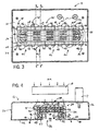
- Fig. 1 is top perspective view of a ventilated sealing head according to the present invention
- Fig. 2 is a bottom perspective view of the ventilated sealing head
- Fig. 3 is a bottom plan view of the ventilated sealing head with the bottom cover removed to show the wire coil and field focusing assembly;
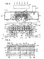
- Fig. 4 is a cross-sectional view taken along line 4-4 of Fig. 3 with a set of field focusing elements shown in cross-section;
- Fig. 5 is a cross-sectional view taken along line 5-5 of Fig. 3 at an opening between the spaced field focusing elements;
- Fig. 6 is a partial enlarged view of Fig. 5 with the housing shown in phantom;
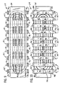
- Fig. 7 is a bottom view taken along lien 7-7 of Fig. 6 showing the field focusing assembly with the electromagnetic coil wound therein and with a center panel of the housing shown cut-away to reveal the coil;
- Fig. 7a is a cross-sectional view similar to Fig. 7 albeit taken along line 7a-7a of Fig. 6;
- Fig. 8 is a cross-sectional view similar to Fig. 7 albeit taken along line 8-8 of Fig. 6;
- Fig. 9 is a cross-sectional view similar to Fig. 7 albeit taken along line 9-9 of Fig. 6;
- Fig. 10 is a top view of the field focusing assembly and coil taken along line 10-10 of Fig. 6;
- Fig. 11 is a side cross-sectional view taken along line 11-11 of Fig. 6 and in partial cut-away to show a coil spacing element
- Fig. 12 is a front perspective view of an induction air cooled cap sealer having a vented sealing head.
- FIG. 12 An air cooled cap sealer 10 is shown in Fig. 12.
- the cap sealer 10 is preferably of the type described in U.S. patent 6,153,864 assigned to the assignee of this application and hereby incorporated by reference as through fully set forth herein.
- the cap sealer 10 has a sealing head 12 powered by and mounted to a power supply cabinet 14 supported on an adjustable mounting assembly 16.
- the sealing head 12 is electrically connected to the power supply cabinet 14 via a pair of bus wires (not shown) coupled to shielded, plug-in type socket connectors mateable with connectors 17 (see Fig. 1) on the sealing head 12.
- two cooling fans 18 are mounted between the sealing head 12 and the power supply cabinet 14, one cooling the sealing head 12 and the other the power supply cabinet 14.
- the sealing head 12 is vented to improve cooling by allowing cooling air to pass through the sealing head 12.
- the sealing head 12 has a housing 20 containing an electromagnetic coil 22 wound about a field focusing coil housing 24 formed by one or more electromagnetic field focusing elements joined together by a suitable epoxy resin.
- the housing 20 is preferably made of an ABS plastic material and comprises an inverted tray 26 and a bottom cover 28.
- the tray 26 has a rectangular top with downwardly extending walls along its periphery.
- the bottom cover has front 30, back 32 and center 34 panels defining a recessed tunnel 36 extending from side to side across the width of the bottom of the sealing head 12.
- the top of the inverted tray 26 has a generally circular grille 38 with a plurality of openings allowing air into the housing 20.
- the front 30 and back 32 panels of the bottom cover 28 each has two rows of lateral slots 40, respectively.
- One of the rows of each panel is located in short legs 41 and 43 forming the sides of the tunnel 36.
- the center panel 34 has four rows of five slots 40 aligned in parallel.
- the bottom cover 28 is fastened to the tray 26 by a suitable adhesive applied to their edges or as disclosed in the '864 patent. When assembled, air can pass into the top of the sealing head 12 through openings in the grille 38 and exit through the slots 40 in the bottom of the sealing head 12.
- the coil housing 24 and coil 22 are disposed around the tunnel 36 to surround it along its length from the top and sides.
- the coil 22 is formed of bundled wire, such as Litz wire, known to those skilled in the art. The number of windings and the gauge of the wire are selected according to the sealing requirements of the application, as known in the art.
- the coil 22 is wound within the coil housing 24 around the tunnel 36 and windings are spaced apart by four sets of four spacers 42 adhered to the center panel 34 of the bottom cover 28 and extending upwardly into the housing 20 (see Figs. 6, 7a and 11).
- the coil housing 24 is comprised of a number of rectangular blocks made of a ferromagnetic compound having ferric oxide, so that, rather than radiating omni-directionally, the electromagnetic field produced by the coil 22 is directed downward to a sealing region 44 within and/or below the tunnel 36.
- the blocks are arranged in ten inverted U-shaped segments 45 having four blocks 46 each, two aligned end to end in the front-back direction of the sealing head 12 and two bookends extending vertically. Each segment 45 is spaced apart in the side to side direction of the sealing head 12, approximately the width of a block.
- Two rows of four blocks 47 are disposed on each side of the tunnel 36 spaced laterally between the coil 22 in the side to side direction.
- Two rows of seven blocks 48 are disposed end to end with their bottom faces against the front 30 and back 32 panels of the bottom cover 28 on each side of the tunnel 36 beneath the two rows of four blocks 47. These seven blocks 48 are not spaced in the side to side direction so as to provide a rigid corner along much of the tunnel 36.
- a row of five blocks 49 are disposed end to end on their side edges along the center of the center panel 34 extending in the side to side direction of the sealing head 12 between the coil 22.
- the arrangement of the field focusing blocks forming the coil housing 24 has been empirically shown to direct the electromagnetic field toward the sealing region 44 while allowing air entering the housing 20 to pass by the blocks. Air is blown by the fans above the sealing head 12 into the grille openings in the top of the tray 26 and some air will exit the sealing head housing 20 through the centermost slots 40 in the bottom cover 28. A portion of the air flow, however, is interrupted by the blocks and/or the coil 22 such that it will circulate through the sealing head 12 from front to back and side to side allowing most, if not all, of the coil 22 and coil housing 24 to be cooled convectively. Moreover, warmer portions of the coil 22 will pass heat to cooler portions of the coil 22 so that the coil 22 will be conductively cooled as well.
- the invention thus provides a vented sealing head for an inductive cap sealer and a cap sealer having such a sealing head. Venting the sealing heat allows cooling air to be blown passed the coil and field focusing elements to carry away heat from these components and convectively cool the sealing head.
- the sealing head can thus be cooled without a separate cooling circuit and without the costly and difficult to assemble tubing arrangements associated with liquid cooling.
- the cap sealer 10 is operated by first adjusting it vertically if needed according to the height of a container 50 to be sealed.
- the mouth of the container 50 is then covered with an inner seal 52 having a polymer layer laminated to an aluminum foil layer.
- a cap 54 is snapped, screwed or otherwise fit onto the mouth of the container 50, which places a downward force on the inner seal 52.
- the container 50 is then placed upright with the cap 54 under the sealing head 12 in the sealing region 46.
- Applying power to the coil 22 produces an electromagnetic field directed downwardly from the sealing head 12 to the sealing region 46 for a prescribed period of time which heats the foil layer and melts the polymer layer.
- the container 50 is removed from beneath the sealing head 12 which allows the polymer layer to cool and fuse to the mouth of the container 50.
- the cap sealer 10 may be operated manually, placing one container 50 at a time beneath the sealing head 12, or it may be used to seal a number of containers 50 continuously or intermittently passing through the electromagnetic field under the sealing head 12 on a conveyor belt or similar assembly line.
- the sealing head can be interchangeably mounted to the power supply cabinet so that sealing heads of other configurations may be used for various sealing applications, such as a vented flat sealing head particularly suitable for wide necked containers.
- the sealing head may have more than one induction coil mounted in various orientations and the coil housing could be monolithic with openings made therein for air to flow through the coil housing and past the coil.
Abstract
Description
- Not applicable.
- The invention relates to the field of heat sealing caps to containers. In particular, the invention relates to air cooled sealing heads.
- It is known to seal the mouths of bottles and other containers using an inductive sealing process. Inductive sealing requires an electromagnetic-field-producing apparatus and a foil-polymer seal. Typically, the apparatus has at least one coil of wire wound to produce an electromagnetic field when electric current is supplied to the coil. It is well known in the art that electromagnetic fields induce eddy currents within metal which in turn heat the metal. The seal comprises a thin layer of aluminum foil onto which is laminated a polymer layer that is molecularly compatible with the container to be sealed. When the seal is placed onto the container and the container is placed within the electromagnetic field, the foil is heated which melts the layer of polymer. Removing the seal from the electromagnetic field allows the polymer to cool and molecularly fuse with the container to create an air-tight seal.
- The electromagnetic field strength primarily depends upon the number of turns in the wire coils and the amount of current supplied to the coils. To produce an electromagnetic field adequate for commercial inductive sealing, typically the power supply must output power in the order of a few kilowatts, which produces a great deal of heat. Thus, the power supply must be cooled in order to function properly. Similarly, the sealing head having the induction coil must be cooled.
- Many methods of cooling the power supply and sealing head are known in the art. In particular, it is known to circulate cool water through the power supply enclosure and the sealing head. Such water cooled cap sealers, however, require complicated piping configurations that increase size and cost. It is also known to vent the power supply and force air past the outside of the sealing head. However, such air cooled cap sealers sometimes provide inadequate cooling of the sealing head which degrades the operating efficiency of the cap sealer.
A ventilated sealing head comprising the features of the generic part ofclaim 1 and an apparatus for inductively sealing comprising the features of the generic part ofclaim 7 are known from document US 6,153,864. In particular, from this document, an air cooled cap sealer is known, which comprises a power supply for producing alternating current and an external sealing head mounted to the power supply. The sealing head comprises a housing containing an induction coil for producing an electromagnetic field when energized by the power supply and field focusing elements partly surrounding the coil and directing the electromagnetic field to a sealing region beneath the sealing head.
Further, document EP 0 818 791 A1 discloses a high power transformer having a printed circuit board with holes for air circulation. - The invention provides a ventilated sealing head for an inductive cap sealer. Specifically, the sealing head includes an induction coil for producing an electromagnetic field. One or more field focusing elements are disposed adjacent the coil to direct the electromagnetic field of the coil toward a sealing region beneath the sealing head. The coil and the field focusing elements are contained in a housing having openings allowing air to flow past the coil.
- In a preferred form, the field focusing elements are a ferromagnetic compound and there are a plurality of field focusing elements spaced apart along at least a portion of the periphery of the coil allowing air to flow between the spaced field focusing elements and past the coil.
- In other forms, the housing forms a tunnel extending lengthwise from side to side of the sealing head and opening downward at the sealing region. The coil is wound around the tunnel and within a number of electromagnetic field focusing elements. The sealing head further includes a pair of plug-in shielded connectors for coupling the coil to power.
- Another aspect of the invention is a cap sealer having an AC power supply and an external vented sealing head as described above. The cap sealer can further include an external fan disposed between the sealing head and the power supply for forcing cooling air through the sealing head.
- The invention thus provides a vented sealing head for an inductive cap sealer. Venting the sealing head allows cooling air to be blown passed the coil and field focusing elements to carry away heat from these components and convectively cool the sealing head. The sealing head can thus be cooled without a separate cooling circuit and without the costly and difficult to assemble tubing arrangements associated with liquid cooling.
- The foregoing and other advantages of the invention will appear from the following description. In that description reference is made to the accompanying drawings, which form a part hereof, and in which there is shown by way of illustration a preferred embodiment of the invention.
- Fig. 1 is top perspective view of a ventilated sealing head according to the present invention;
- Fig. 2 is a bottom perspective view of the ventilated sealing head;
- Fig. 3 is a bottom plan view of the ventilated sealing head with the bottom cover removed to show the wire coil and field focusing assembly;
- Fig. 4 is a cross-sectional view taken along line 4-4 of Fig. 3 with a set of field focusing elements shown in cross-section;
- Fig. 5 is a cross-sectional view taken along line 5-5 of Fig. 3 at an opening between the spaced field focusing elements;
- Fig. 6 is a partial enlarged view of Fig. 5 with the housing shown in phantom;
- Fig. 7 is a bottom view taken along lien 7-7 of Fig. 6 showing the field focusing assembly with the electromagnetic coil wound therein and with a center panel of the housing shown cut-away to reveal the coil;
- Fig. 7a is a cross-sectional view similar to Fig. 7 albeit taken along
line 7a-7a of Fig. 6; - Fig. 8 is a cross-sectional view similar to Fig. 7 albeit taken along line 8-8 of Fig. 6;
- Fig. 9 is a cross-sectional view similar to Fig. 7 albeit taken along line 9-9 of Fig. 6;
- Fig. 10 is a top view of the field focusing assembly and coil taken along line 10-10 of Fig. 6;
- Fig. 11 is a side cross-sectional view taken along line 11-11 of Fig. 6 and in partial cut-away to show a coil spacing element; and
- Fig. 12 is a front perspective view of an induction air cooled cap sealer having a vented sealing head.
- An air cooled
cap sealer 10 is shown in Fig. 12. Thecap sealer 10 is preferably of the type described in U.S. patent 6,153,864 assigned to the assignee of this application and hereby incorporated by reference as through fully set forth herein. Generally, thecap sealer 10 has a sealinghead 12 powered by and mounted to apower supply cabinet 14 supported on anadjustable mounting assembly 16. The sealinghead 12 is electrically connected to thepower supply cabinet 14 via a pair of bus wires (not shown) coupled to shielded, plug-in type socket connectors mateable with connectors 17 (see Fig. 1) on the sealinghead 12. Preferably, two cooling fans 18 (one shown in Figs. 4 and 5) are mounted between the sealinghead 12 and thepower supply cabinet 14, one cooling the sealinghead 12 and the other thepower supply cabinet 14. The sealinghead 12 is vented to improve cooling by allowing cooling air to pass through the sealinghead 12. - Referring to Figs. 1, 2 and 3, the sealing
head 12 has ahousing 20 containing anelectromagnetic coil 22 wound about a field focusingcoil housing 24 formed by one or more electromagnetic field focusing elements joined together by a suitable epoxy resin. Thehousing 20 is preferably made of an ABS plastic material and comprises aninverted tray 26 and abottom cover 28. Thetray 26 has a rectangular top with downwardly extending walls along its periphery. The bottom cover hasfront 30, back 32 andcenter 34 panels defining a recessedtunnel 36 extending from side to side across the width of the bottom of the sealinghead 12. The top of theinverted tray 26 has a generallycircular grille 38 with a plurality of openings allowing air into thehousing 20. The front 30 and back 32 panels of thebottom cover 28 each has two rows oflateral slots 40, respectively. One of the rows of each panel is located inshort legs tunnel 36. Thecenter panel 34 has four rows of fiveslots 40 aligned in parallel. Thebottom cover 28 is fastened to thetray 26 by a suitable adhesive applied to their edges or as disclosed in the '864 patent. When assembled, air can pass into the top of the sealinghead 12 through openings in thegrille 38 and exit through theslots 40 in the bottom of the sealinghead 12. - Referring to Figs. 4-6, the
coil housing 24 andcoil 22 are disposed around thetunnel 36 to surround it along its length from the top and sides. Thecoil 22 is formed of bundled wire, such as Litz wire, known to those skilled in the art. The number of windings and the gauge of the wire are selected according to the sealing requirements of the application, as known in the art. Thecoil 22 is wound within thecoil housing 24 around thetunnel 36 and windings are spaced apart by four sets of fourspacers 42 adhered to thecenter panel 34 of thebottom cover 28 and extending upwardly into the housing 20 (see Figs. 6, 7a and 11). - Referring still to Figs. 4-6 as well as Figs. 7-11, the
coil housing 24 is comprised of a number of rectangular blocks made of a ferromagnetic compound having ferric oxide, so that, rather than radiating omni-directionally, the electromagnetic field produced by thecoil 22 is directed downward to a sealingregion 44 within and/or below thetunnel 36. In the embodiment shown in the figures, the blocks are arranged in ten invertedU-shaped segments 45 having fourblocks 46 each, two aligned end to end in the front-back direction of the sealinghead 12 and two bookends extending vertically. Eachsegment 45 is spaced apart in the side to side direction of the sealinghead 12, approximately the width of a block. Two rows of fourblocks 47 are disposed on each side of thetunnel 36 spaced laterally between thecoil 22 in the side to side direction. Two rows of sevenblocks 48 are disposed end to end with their bottom faces against the front 30 and back 32 panels of thebottom cover 28 on each side of thetunnel 36 beneath the two rows of fourblocks 47. These sevenblocks 48 are not spaced in the side to side direction so as to provide a rigid corner along much of thetunnel 36. Finally, a row of fiveblocks 49 are disposed end to end on their side edges along the center of thecenter panel 34 extending in the side to side direction of the sealinghead 12 between thecoil 22. - The arrangement of the field focusing blocks forming the
coil housing 24 has been empirically shown to direct the electromagnetic field toward the sealingregion 44 while allowing air entering thehousing 20 to pass by the blocks. Air is blown by the fans above the sealinghead 12 into the grille openings in the top of thetray 26 and some air will exit the sealinghead housing 20 through thecentermost slots 40 in thebottom cover 28. A portion of the air flow, however, is interrupted by the blocks and/or thecoil 22 such that it will circulate through the sealinghead 12 from front to back and side to side allowing most, if not all, of thecoil 22 andcoil housing 24 to be cooled convectively. Moreover, warmer portions of thecoil 22 will pass heat to cooler portions of thecoil 22 so that thecoil 22 will be conductively cooled as well. - The invention thus provides a vented sealing head for an inductive cap sealer and a cap sealer having such a sealing head. Venting the sealing heat allows cooling air to be blown passed the coil and field focusing elements to carry away heat from these components and convectively cool the sealing head. The sealing head can thus be cooled without a separate cooling circuit and without the costly and difficult to assemble tubing arrangements associated with liquid cooling.
- With reference to Figs. 3 and 12, the
cap sealer 10 is operated by first adjusting it vertically if needed according to the height of acontainer 50 to be sealed. The mouth of thecontainer 50 is then covered with aninner seal 52 having a polymer layer laminated to an aluminum foil layer. A cap 54 is snapped, screwed or otherwise fit onto the mouth of thecontainer 50, which places a downward force on theinner seal 52. Thecontainer 50 is then placed upright with the cap 54 under the sealinghead 12 in the sealingregion 46. Applying power to thecoil 22 produces an electromagnetic field directed downwardly from the sealinghead 12 to the sealingregion 46 for a prescribed period of time which heats the foil layer and melts the polymer layer. Thecontainer 50 is removed from beneath the sealinghead 12 which allows the polymer layer to cool and fuse to the mouth of thecontainer 50. Thecap sealer 10 may be operated manually, placing onecontainer 50 at a time beneath the sealinghead 12, or it may be used to seal a number ofcontainers 50 continuously or intermittently passing through the electromagnetic field under the sealinghead 12 on a conveyor belt or similar assembly line. - Illustrative embodiments of the invention have been described in considerable detail for the purpose of disclosing practical, operative structures whereby the invention may be practiced advantageously. The designs described are intended to be illustrative only. The novel characteristics of the invention may be incorporated in other structural forms without departing from the scope of the invention. For example, the sealing head can be interchangeably mounted to the power supply cabinet so that sealing heads of other configurations may be used for various sealing applications, such as a vented flat sealing head particularly suitable for wide necked containers. Moreover, the sealing head may have more than one induction coil mounted in various orientations and the coil housing could be monolithic with openings made therein for air to flow through the coil housing and past the coil.
Claims (9)
- A ventilated sealing head for an inductive cap sealing apparatus, comprising:an induction coil (22) for producing an electromagnetic field;one or more field focusing elements (45) disposed to at least partially surround the coil (22) and direct the electromagnetic field of the coil (22) toward a sealing region (44) beneath the sealing head (12); anda housing (20) containing the coil (22) and the field focusing elements (45),characterized in that,
said housing (20) has openings (38, 40) allowing air to flow past the coil. - The sealing head of claim 1, wherein there are a plurality of field focusing elements (45) spaced apart along at least a portion of the periphery of the coil (22) allowing air to flow between the spaced field focusing elements (45).
- The sealing head of claim 1, wherein the field focusing elements (45) are a ferromagnetic compound.
- The sealing head of claim 1, wherein the housing (20) forms a lengthwise tunnel (36) opening downward at the sealing region (44).
- The sealing head of claim 4, wherein the coil (22) and the field focusing elements (45) are disposed within the housing (20) around the tunnel (36).
- The sealing head of claim 1, wherein the coil (22) is bundled wire.
- The sealing head of claim 1, further including a pair of shielded connectors (17) for coupling the coil (22) to power.
- An apparatus for inductively sealing an inner seal over an opening in a container, comprising:a power supply (14) for producing alternating current;an external sealing head (12) mounted to the power supply (14) having a housing (20) containing an induction coil (22) for producing an electromagnetic field when energized by the power supply (14) and field focusing elements (45) arranged to at least in part surround the coil (22) and direct the electromagnetic field to a sealing region (44) beneath the sealing head,characterized in that,
the housing (20) has openings (38, 40) allowing air to flow past the coil. - The apparatus of claim 8, further including an external fan disposed between the sealing head and the power supply so as to force air into the openings in the housing.
Applications Claiming Priority (3)
| Application Number | Priority Date | Filing Date | Title |
|---|---|---|---|
| US970330 | 1992-11-02 | ||
| US09/970,330 US6649022B2 (en) | 2001-10-03 | 2001-10-03 | Ventilated sealing head for induction sealer |
| PCT/US2002/031236 WO2003030590A2 (en) | 2001-10-03 | 2002-10-01 | Ventilated sealing head for induction sealer |
Publications (2)
| Publication Number | Publication Date |
|---|---|
| EP1433362A2 EP1433362A2 (en) | 2004-06-30 |
| EP1433362B1 true EP1433362B1 (en) | 2006-05-03 |
Family
ID=25516779
Family Applications (1)
| Application Number | Title | Priority Date | Filing Date |
|---|---|---|---|
| EP02763820A Expired - Lifetime EP1433362B1 (en) | 2001-10-03 | 2002-10-01 | Ventilated sealing head for induction sealer |
Country Status (4)
| Country | Link |
|---|---|
| US (1) | US6649022B2 (en) |
| EP (1) | EP1433362B1 (en) |
| AT (1) | ATE325522T1 (en) |
| DE (1) | DE60211188T2 (en) |
Families Citing this family (6)
| Publication number | Priority date | Publication date | Assignee | Title |
|---|---|---|---|---|
| ATE471650T1 (en) | 2002-04-12 | 2010-07-15 | Enercon Ind Corp | VENTILATED SEAL HEAD WITH U-FLOW |
| ATE456513T1 (en) * | 2007-03-06 | 2010-02-15 | Huettinger Elektronik Gmbh | FLEXIBLE INDUCTOR FOR INDUCTIVE SEALING OF CONTRACTS |
| US7834298B2 (en) * | 2007-11-26 | 2010-11-16 | Ultraflex International, Inc. | Adjustable electromagnetic sealing device |
| US9216542B2 (en) * | 2008-04-23 | 2015-12-22 | Illinois Tool Works Inc. | Electrical connection between sealing coil and voltage source |
| EP2695484B1 (en) * | 2011-04-05 | 2015-10-14 | Comaintel, Inc. | Induction heating workcoil |
| US10889411B2 (en) * | 2017-02-03 | 2021-01-12 | Berry Plastics Corporation | Container with lid and detachable lid collar |
Family Cites Families (7)
| Publication number | Priority date | Publication date | Assignee | Title |
|---|---|---|---|---|
| US4095390A (en) | 1976-04-01 | 1978-06-20 | Mckenna Equipment Company, Inc. | Machine and process for capping and sealing containers |
| US4707213A (en) | 1985-11-12 | 1987-11-17 | Continental Can Company, Inc. | Induction heating unit for heat bonding a lid having a metallic layer to a container |
| JPH09262211A (en) | 1996-03-29 | 1997-10-07 | Canon Inc | Ophthalmological photographing apparatus |
| DE19627585A1 (en) | 1996-07-09 | 1998-01-15 | Thomson Brandt Gmbh | High voltage transformer for a television receiver |
| USD398314S (en) | 1996-11-05 | 1998-09-15 | Auto-Mate Technologies, L.L.C. | Induction foil cap sealer |
| DE69704191T2 (en) | 1996-11-15 | 2001-08-16 | Auto Mate Technologies Llc | Device for induction sealing a film cap on a container opening |
| US6552312B2 (en) * | 2000-03-01 | 2003-04-22 | Enercon Industries Corporation | Adjustable cap sealer head |
-
2001
- 2001-10-03 US US09/970,330 patent/US6649022B2/en not_active Expired - Lifetime
-
2002
- 2002-10-01 EP EP02763820A patent/EP1433362B1/en not_active Expired - Lifetime
- 2002-10-01 AT AT02763820T patent/ATE325522T1/en not_active IP Right Cessation
- 2002-10-01 DE DE60211188T patent/DE60211188T2/en not_active Expired - Lifetime
Also Published As
| Publication number | Publication date |
|---|---|
| DE60211188T2 (en) | 2007-02-22 |
| ATE325522T1 (en) | 2006-06-15 |
| DE60211188D1 (en) | 2006-06-08 |
| US6649022B2 (en) | 2003-11-18 |
| WO2003030590A1 (en) | 2003-04-10 |
| EP1433362A2 (en) | 2004-06-30 |
| WO2003030590A3 (en) | 2003-05-22 |
| US20030062130A1 (en) | 2003-04-03 |
Similar Documents
| Publication | Publication Date | Title |
|---|---|---|
| EP1495656B1 (en) | U-flow ventilated sealing head | |
| US20230089953A1 (en) | Stationary induction charging device for wireless energy transfer | |
| ES2554807T3 (en) | Induction heater | |
| EP3509075B1 (en) | Wireless device charger with cooling device | |
| EP1433362B1 (en) | Ventilated sealing head for induction sealer | |
| EP0842854B1 (en) | Induction sealing apparatus for sealing a foil cap to a container opening | |
| US6989518B2 (en) | Method of sealing a foil cap to a container | |
| KR102659990B1 (en) | Induction heating device having improved ferrite core shape | |
| EP1426984B1 (en) | Transformer assembly for microwave oven, method for manufacturing the same, and microwave oven having the same | |
| EP3547799A1 (en) | Induction heating device having reduced number of wire harnesses | |
| US6875965B2 (en) | Multiple head induction sealer apparatus and method | |
| US6633480B1 (en) | Air-cooled induction foil cap sealer | |
| KR102641091B1 (en) | Induction heating device having improved insulation structure | |
| JP2004171926A (en) | Induction heating device | |
| US4740663A (en) | Transverse flux induction heating unit | |
| WO2003030590A2 (en) | Ventilated sealing head for induction sealer | |
| KR102251058B1 (en) | Induction heating cooker | |
| GB2282058B (en) | Cooling air ventilation device for induction heating jar | |
| US6153864A (en) | Spray washable air cooled cap sealer | |
| US20220289047A1 (en) | Inductive Power Transfer Pad and Method for Producing an Inductive Power Transfer Pad | |
| CN1179611A (en) | High voltage transformer | |
| CN209074140U (en) | Cooking utensil | |
| CA2345198C (en) | Induction foil cap sealer | |
| JP3458678B2 (en) | Inverter power supply for high frequency heating device | |
| CN114974811A (en) | Dry-type phase-shifting transformer |
Legal Events
| Date | Code | Title | Description |
|---|---|---|---|
| PUAI | Public reference made under article 153(3) epc to a published international application that has entered the european phase |
Free format text: ORIGINAL CODE: 0009012 |
|
| 17P | Request for examination filed |
Effective date: 20040402 |
|
| AK | Designated contracting states |
Kind code of ref document: A2 Designated state(s): AT BE BG CH CY CZ DE DK EE ES FI FR GB GR IE IT LI LU MC NL PT SE SK TR |
|
| AX | Request for extension of the european patent |
Extension state: AL LT LV MK RO SI |
|
| RIN1 | Information on inventor provided before grant (corrected) |
Inventor name: MAY, RONALD, J. Inventor name: HAMMEN, RICHARD, R. |
|
| 17Q | First examination report despatched |
Effective date: 20040706 |
|
| RIN1 | Information on inventor provided before grant (corrected) |
Inventor name: HAMMEN, RICHARD, R.,ENERCON INDUSTRIES CORP. Inventor name: MAY, RONALD, J. |
|
| GRAP | Despatch of communication of intention to grant a patent |
Free format text: ORIGINAL CODE: EPIDOSNIGR1 |
|
| GRAS | Grant fee paid |
Free format text: ORIGINAL CODE: EPIDOSNIGR3 |
|
| GRAA | (expected) grant |
Free format text: ORIGINAL CODE: 0009210 |
|
| AK | Designated contracting states |
Kind code of ref document: B1 Designated state(s): AT BE BG CH CY CZ DE DK EE ES FI FR GB GR IE IT LI LU MC NL PT SE SK TR |
|
| PG25 | Lapsed in a contracting state [announced via postgrant information from national office to epo] |
Ref country code: IT Free format text: LAPSE BECAUSE OF FAILURE TO SUBMIT A TRANSLATION OF THE DESCRIPTION OR TO PAY THE FEE WITHIN THE PRESCRIBED TIME-LIMIT;WARNING: LAPSES OF ITALIAN PATENTS WITH EFFECTIVE DATE BEFORE 2007 MAY HAVE OCCURRED AT ANY TIME BEFORE 2007. THE CORRECT EFFECTIVE DATE MAY BE DIFFERENT FROM THE ONE RECORDED. Effective date: 20060503 Ref country code: AT Free format text: LAPSE BECAUSE OF FAILURE TO SUBMIT A TRANSLATION OF THE DESCRIPTION OR TO PAY THE FEE WITHIN THE PRESCRIBED TIME-LIMIT Effective date: 20060503 Ref country code: CZ Free format text: LAPSE BECAUSE OF FAILURE TO SUBMIT A TRANSLATION OF THE DESCRIPTION OR TO PAY THE FEE WITHIN THE PRESCRIBED TIME-LIMIT Effective date: 20060503 Ref country code: LI Free format text: LAPSE BECAUSE OF FAILURE TO SUBMIT A TRANSLATION OF THE DESCRIPTION OR TO PAY THE FEE WITHIN THE PRESCRIBED TIME-LIMIT Effective date: 20060503 Ref country code: CH Free format text: LAPSE BECAUSE OF FAILURE TO SUBMIT A TRANSLATION OF THE DESCRIPTION OR TO PAY THE FEE WITHIN THE PRESCRIBED TIME-LIMIT Effective date: 20060503 Ref country code: NL Free format text: LAPSE BECAUSE OF FAILURE TO SUBMIT A TRANSLATION OF THE DESCRIPTION OR TO PAY THE FEE WITHIN THE PRESCRIBED TIME-LIMIT Effective date: 20060503 Ref country code: SK Free format text: LAPSE BECAUSE OF FAILURE TO SUBMIT A TRANSLATION OF THE DESCRIPTION OR TO PAY THE FEE WITHIN THE PRESCRIBED TIME-LIMIT Effective date: 20060503 Ref country code: FI Free format text: LAPSE BECAUSE OF FAILURE TO SUBMIT A TRANSLATION OF THE DESCRIPTION OR TO PAY THE FEE WITHIN THE PRESCRIBED TIME-LIMIT Effective date: 20060503 Ref country code: BE Free format text: LAPSE BECAUSE OF FAILURE TO SUBMIT A TRANSLATION OF THE DESCRIPTION OR TO PAY THE FEE WITHIN THE PRESCRIBED TIME-LIMIT Effective date: 20060503 |
|
| REG | Reference to a national code |
Ref country code: GB Ref legal event code: FG4D |
|
| REG | Reference to a national code |
Ref country code: CH Ref legal event code: EP |
|
| REF | Corresponds to: |
Ref document number: 60211188 Country of ref document: DE Date of ref document: 20060608 Kind code of ref document: P |
|
| REG | Reference to a national code |
Ref country code: IE Ref legal event code: FG4D |
|
| PG25 | Lapsed in a contracting state [announced via postgrant information from national office to epo] |
Ref country code: DK Free format text: LAPSE BECAUSE OF FAILURE TO SUBMIT A TRANSLATION OF THE DESCRIPTION OR TO PAY THE FEE WITHIN THE PRESCRIBED TIME-LIMIT Effective date: 20060803 Ref country code: SE Free format text: LAPSE BECAUSE OF FAILURE TO SUBMIT A TRANSLATION OF THE DESCRIPTION OR TO PAY THE FEE WITHIN THE PRESCRIBED TIME-LIMIT Effective date: 20060803 |
|
| PG25 | Lapsed in a contracting state [announced via postgrant information from national office to epo] |
Ref country code: ES Free format text: LAPSE BECAUSE OF FAILURE TO SUBMIT A TRANSLATION OF THE DESCRIPTION OR TO PAY THE FEE WITHIN THE PRESCRIBED TIME-LIMIT Effective date: 20060814 |
|
| PG25 | Lapsed in a contracting state [announced via postgrant information from national office to epo] |
Ref country code: IE Free format text: LAPSE BECAUSE OF NON-PAYMENT OF DUE FEES Effective date: 20061002 |
|
| PG25 | Lapsed in a contracting state [announced via postgrant information from national office to epo] |
Ref country code: PT Free format text: LAPSE BECAUSE OF FAILURE TO SUBMIT A TRANSLATION OF THE DESCRIPTION OR TO PAY THE FEE WITHIN THE PRESCRIBED TIME-LIMIT Effective date: 20061003 |
|
| PG25 | Lapsed in a contracting state [announced via postgrant information from national office to epo] |
Ref country code: MC Free format text: LAPSE BECAUSE OF NON-PAYMENT OF DUE FEES Effective date: 20061031 |
|
| NLV1 | Nl: lapsed or annulled due to failure to fulfill the requirements of art. 29p and 29m of the patents act | ||
| REG | Reference to a national code |
Ref country code: CH Ref legal event code: PL |
|
| PLBE | No opposition filed within time limit |
Free format text: ORIGINAL CODE: 0009261 |
|
| STAA | Information on the status of an ep patent application or granted ep patent |
Free format text: STATUS: NO OPPOSITION FILED WITHIN TIME LIMIT |
|
| 26N | No opposition filed |
Effective date: 20070206 |
|
| EN | Fr: translation not filed | ||
| PG25 | Lapsed in a contracting state [announced via postgrant information from national office to epo] |
Ref country code: FR Free format text: LAPSE BECAUSE OF FAILURE TO SUBMIT A TRANSLATION OF THE DESCRIPTION OR TO PAY THE FEE WITHIN THE PRESCRIBED TIME-LIMIT Effective date: 20070309 Ref country code: GR Free format text: LAPSE BECAUSE OF FAILURE TO SUBMIT A TRANSLATION OF THE DESCRIPTION OR TO PAY THE FEE WITHIN THE PRESCRIBED TIME-LIMIT Effective date: 20060804 |
|
| PG25 | Lapsed in a contracting state [announced via postgrant information from national office to epo] |
Ref country code: EE Free format text: LAPSE BECAUSE OF FAILURE TO SUBMIT A TRANSLATION OF THE DESCRIPTION OR TO PAY THE FEE WITHIN THE PRESCRIBED TIME-LIMIT Effective date: 20060503 Ref country code: BG Free format text: LAPSE BECAUSE OF FAILURE TO SUBMIT A TRANSLATION OF THE DESCRIPTION OR TO PAY THE FEE WITHIN THE PRESCRIBED TIME-LIMIT Effective date: 20060803 |
|
| PG25 | Lapsed in a contracting state [announced via postgrant information from national office to epo] |
Ref country code: TR Free format text: LAPSE BECAUSE OF FAILURE TO SUBMIT A TRANSLATION OF THE DESCRIPTION OR TO PAY THE FEE WITHIN THE PRESCRIBED TIME-LIMIT Effective date: 20060503 Ref country code: LU Free format text: LAPSE BECAUSE OF NON-PAYMENT OF DUE FEES Effective date: 20061001 |
|
| PG25 | Lapsed in a contracting state [announced via postgrant information from national office to epo] |
Ref country code: FR Free format text: LAPSE BECAUSE OF FAILURE TO SUBMIT A TRANSLATION OF THE DESCRIPTION OR TO PAY THE FEE WITHIN THE PRESCRIBED TIME-LIMIT Effective date: 20060503 Ref country code: CY Free format text: LAPSE BECAUSE OF FAILURE TO SUBMIT A TRANSLATION OF THE DESCRIPTION OR TO PAY THE FEE WITHIN THE PRESCRIBED TIME-LIMIT Effective date: 20060503 |
|
| PGFP | Annual fee paid to national office [announced via postgrant information from national office to epo] |
Ref country code: DE Payment date: 20151002 Year of fee payment: 14 |
|
| REG | Reference to a national code |
Ref country code: DE Ref legal event code: R119 Ref document number: 60211188 Country of ref document: DE |
|
| PG25 | Lapsed in a contracting state [announced via postgrant information from national office to epo] |
Ref country code: DE Free format text: LAPSE BECAUSE OF NON-PAYMENT OF DUE FEES Effective date: 20170503 |
|
| PGFP | Annual fee paid to national office [announced via postgrant information from national office to epo] |
Ref country code: GB Payment date: 20211027 Year of fee payment: 20 |
|
| PGFP | Annual fee paid to national office [announced via postgrant information from national office to epo] |
Ref country code: IT Payment date: 20211021 Year of fee payment: 20 |
|
| REG | Reference to a national code |
Ref country code: GB Ref legal event code: PE20 Expiry date: 20220930 |
|
| PG25 | Lapsed in a contracting state [announced via postgrant information from national office to epo] |
Ref country code: GB Free format text: LAPSE BECAUSE OF EXPIRATION OF PROTECTION Effective date: 20220930 |