EP1432935B1 - Shifting arm - Google Patents
Shifting arm Download PDFInfo
- Publication number
- EP1432935B1 EP1432935B1 EP02800581A EP02800581A EP1432935B1 EP 1432935 B1 EP1432935 B1 EP 1432935B1 EP 02800581 A EP02800581 A EP 02800581A EP 02800581 A EP02800581 A EP 02800581A EP 1432935 B1 EP1432935 B1 EP 1432935B1
- Authority
- EP
- European Patent Office
- Prior art keywords
- gearshift
- gearshift arm
- edge
- recess
- arm according
- Prior art date
- Legal status (The legal status is an assumption and is not a legal conclusion. Google has not performed a legal analysis and makes no representation as to the accuracy of the status listed.)
- Expired - Fee Related
Links
- 239000002184 metal Substances 0.000 claims description 32
- 239000000463 material Substances 0.000 claims description 11
- 238000000034 method Methods 0.000 claims description 8
- 229910000831 Steel Inorganic materials 0.000 claims description 7
- 239000010959 steel Substances 0.000 claims description 7
- 238000003466 welding Methods 0.000 claims description 7
- 238000007493 shaping process Methods 0.000 claims description 2
- 230000002035 prolonged effect Effects 0.000 claims 2
- 239000000956 alloy Substances 0.000 claims 1
- 229910045601 alloy Inorganic materials 0.000 claims 1
- 238000005520 cutting process Methods 0.000 description 21
- 238000004519 manufacturing process Methods 0.000 description 8
- 238000003754 machining Methods 0.000 description 7
- 230000015572 biosynthetic process Effects 0.000 description 5
- 238000004049 embossing Methods 0.000 description 4
- 238000004080 punching Methods 0.000 description 4
- 239000011324 bead Substances 0.000 description 3
- 230000005540 biological transmission Effects 0.000 description 3
- 239000007858 starting material Substances 0.000 description 3
- 230000000903 blocking effect Effects 0.000 description 2
- 240000006240 Linum usitatissimum Species 0.000 description 1
- 238000004873 anchoring Methods 0.000 description 1
- 238000005452 bending Methods 0.000 description 1
- 238000010276 construction Methods 0.000 description 1
- 238000009499 grossing Methods 0.000 description 1
- 230000006698 induction Effects 0.000 description 1
- 238000009434 installation Methods 0.000 description 1
- 230000002093 peripheral effect Effects 0.000 description 1
- 238000005096 rolling process Methods 0.000 description 1
Images

Classifications
-
- F—MECHANICAL ENGINEERING; LIGHTING; HEATING; WEAPONS; BLASTING
- F16—ENGINEERING ELEMENTS AND UNITS; GENERAL MEASURES FOR PRODUCING AND MAINTAINING EFFECTIVE FUNCTIONING OF MACHINES OR INSTALLATIONS; THERMAL INSULATION IN GENERAL
- F16H—GEARING
- F16H63/00—Control outputs from the control unit to change-speed- or reversing-gearings for conveying rotary motion or to other devices than the final output mechanism
- F16H63/02—Final output mechanisms therefor; Actuating means for the final output mechanisms
- F16H63/30—Constructional features of the final output mechanisms
- F16H63/32—Gear shift yokes, e.g. shift forks
- F16H2063/322—Gear shift yokes, e.g. shift forks characterised by catches or notches for moving the fork
-
- F—MECHANICAL ENGINEERING; LIGHTING; HEATING; WEAPONS; BLASTING
- F16—ENGINEERING ELEMENTS AND UNITS; GENERAL MEASURES FOR PRODUCING AND MAINTAINING EFFECTIVE FUNCTIONING OF MACHINES OR INSTALLATIONS; THERMAL INSULATION IN GENERAL
- F16H—GEARING
- F16H63/00—Control outputs from the control unit to change-speed- or reversing-gearings for conveying rotary motion or to other devices than the final output mechanism
- F16H63/02—Final output mechanisms therefor; Actuating means for the final output mechanisms
- F16H63/30—Constructional features of the final output mechanisms
- F16H63/32—Gear shift yokes, e.g. shift forks
- F16H2063/327—Gear shift yokes, e.g. shift forks essentially made of sheet metal
-
- Y—GENERAL TAGGING OF NEW TECHNOLOGICAL DEVELOPMENTS; GENERAL TAGGING OF CROSS-SECTIONAL TECHNOLOGIES SPANNING OVER SEVERAL SECTIONS OF THE IPC; TECHNICAL SUBJECTS COVERED BY FORMER USPC CROSS-REFERENCE ART COLLECTIONS [XRACs] AND DIGESTS
- Y10—TECHNICAL SUBJECTS COVERED BY FORMER USPC
- Y10T—TECHNICAL SUBJECTS COVERED BY FORMER US CLASSIFICATION
- Y10T74/00—Machine element or mechanism
- Y10T74/20—Control lever and linkage systems
- Y10T74/20576—Elements
- Y10T74/20582—Levers
Definitions
- the invention relates to a switching arm made of sheet metal for the transmission of switching movements.
- Such switching arms are fixedly arranged on switching elements such as shift shafts or shift forks.
- the shift shafts are slidably and / or pivotally mounted in the transmission.
- the shift forks sit z.
- the switching elements are moved and / or pivoted by means of a shift finger or a similarly designed actuating element.
- the actuating element engages in a switching jaw or a similarly formed recess on the switching arm and transmits switching movements to the switching element.
- Locking cylinders or the like which prevent a misoperation of gears, also often engage in the shifting mouth.
- the switching arms are usually stamped parts.
- the contact surfaces for the shift finger are in the switching mouth of a switching arm usually opposite each other. Their distance and their alignment must be carried out with a very high accuracy. Likewise, the requirements for the dimensional accuracy of other other functional surfaces in the switching mouth, such. B. functional surfaces for the engagement of a locking cylinder, very high.
- the required accuracies for the functional dimensions, such as the distance of the opposing contact surfaces in the shift mouth, and functional surfaces, as for the switching jaw limiting and required for the gentle tracking of the shift finger in the shift jaw chamfers and rounded edges on body edges are in the rules only to achieve by machining rework. Functional surfaces are partly due to the punching tear after punching at the cutting edge of the parts for a frictional contact with the shift finger too rough and must therefore be machined by machining.
- the material used for producing the switching arms is relatively high.
- the switching arms are relatively heavy due to their massive construction and their shape design is limited due to the material thickness of the starting material.
- the production of the switching arms is very costly for the above reasons, especially in mass production and mass production.
- a switching arm of the generic type shows FR 27 62 659.
- a switch arm made of thick sheet metal is attached to a shift fork. This switching arm has a switching mouth.
- the wall of the switching arm is reinforced in the field of Wegmaules to create contact surfaces of sufficient width.
- DE 199 19 271 A1 discloses a switching rocker made of sheet metal, which is pre-punched from a blank made of sheet steel before it is formed by a bending operation to the finished component.
- the object of the invention is therefore to provide a switching arm which does not have the aforementioned disadvantages.
- the switching arm is a formed from thin sheet metal forming part.
- the advantages of a switching arm according to the invention in comparison with the prior art are the low costs for its production, especially in mass production and mass production.
- the consumption of material for the production of such a switching arm is low.
- the weight of this switching arm is reduced by up to 50% compared to the switching arms initially described.
- the thin material allows almost unlimited designs.
- the required accuracies for functional dimensions such as the distance of the opposing contact surfaces in the shift jaw, and functional surfaces, as for the location and dimensioning of chamfers and curves for the gentle engagement of the shift finger in the shift jaw, is usually only by the or Form processes achievable. Machining is usually unnecessary.
- the switching arms are preferably used.
- the materials used are sheets made from St35, Ck45, C35 and low-alloyed deep-drawing steels such as 16MnCr5, all weldable and other malleable steels and deep-drawing steels.
- the switching arms are preferably fixed by welding to switching elements, such as shift rails and shift forks.
- a hard surface has in particular the contact surfaces.
- the switching arms according to the invention are surface hardened in the area of the muzzle by induction hardening process. It is also conceivable for reasons of cost to harden the entire switching arm or the switching arm welded to the switching element as a unit. Depending on the type of steel used, case hardening or hardening methods can be used.
- the switching arm is a formed from thin sheet metal formed forming part with a mouth open to an edge of the switching arm recess for the engagement of a shift finger.
- the switching jaw for the engagement of the shift finger is created on the switching arm.
- the switching mouth is z. B. created by a step of excising in a multi-stage forming process or by punching with subsequent embossing or passing through the edges of the muzzle.
- contact surfaces for the shift finger By passing through the edges of the recess or by their embossing are created in a further embodiment of the invention contact surfaces for the shift finger.
- the sheet metal at the edges of the recess is preferably placed through so that the sheet is angled from the actual flat body of the switching arm, usually at right angles but also at any other angle, and possibly forms an edge bordering the entire recess.
- the width of the edge is determined by the required width of the contact surfaces embossed on the edge or produced by means of calibrating and / or depending on the rigidity requirements of the switching arm.
- the contact surfaces for the shift finger lie in the shift mouth usually opposite each other. Their distance and their alignment must be carried out with a very high accuracy. Likewise, the requirements for the dimensional accuracy of other functional surfaces in the switching mouth, such. B. of functional surfaces for the installation of a locking cylinder, very high. These accuracies for the functional dimensions, such as the distance of the opposing contact surfaces in the shift jaw and their orientation to each other, are generally allowable without machining rework.
- the recess is delimited at least by two plane-parallel opposed and mutually facing non-cutting contact surfaces on angled portions of the sheet, wherein the distance between the opposing contact surfaces by non-cutting machining with a Accuracy is performed, which allows a deviation from the target value of the distance of a maximum of 1/10 mm.
- Functional surfaces such as the contact surfaces and as the switching mouth or the contact surfaces delimiting and required for the smooth meshing of the shift finger in the shift mouth chamfers and curves on body edges are introduced without cutting.
- the surface of these functional surfaces is smooth and solidified due to embossing or calibration. The wear resistance of the surfaces is increased. Machining smoothing is eliminated.
- a further embodiment of the invention provides that the recess is bounded at least by two oppositely facing and mutually facing non-cutting shaped contact surfaces on angled portions of the sheet.
- the switching arm has at least one body edge bordering the contact surface, at least on one side to a further lateral surface of the switching arm, with a chamfer formed without a chip.
- a distance describing the bevel in the cross-section of the switching arm between an edge bordering the chamfer surface and an imaginary cutting edge has an accuracy which permits a deviation from the maximum value of the distance of 1/10 mm.
- the imaginary cutting edge is a common cutting edge parallel to the edge of the starting surface extended beyond the chamfer with the further lateral surface of the switching arm extended beyond the chamfer. The distance of the edge separating the abutment surface from the surface created by the chamfer is thus very precisely and more precisely than the distance by machining possible to the vertex of an imaginary unbroken body edge.
- the switching arm is a flat formed of thin sheet metal forming shaped part, wherein the forming part is fork-shaped at one end and is provided at the end with two prong-shaped projections.
- the switching arm also has at least one edge formed by an angled sheet on its outer contour.
- Each of the projections is provided at one of the plate of the switching arm angled portion at least with a stop surface, the one another, opposite to the other of the projections opposite stop surface, opposite.
- the switching arm has at least one tab bent from the switching arm and that the switching arm is connected to a switching element by means of at least one weld on the tab.
- the tab is attached to the switching element by suitable welding methods, such as laser welding, resistance welding or gas shielded arc welding.
- the switching arm is provided with at least one bead-like shape.
- the switching arm Against buckling of the switching arm and to increase the torsional rigidity of the switching arm on the various wall sections is appropriately provided with one or more beads, non-cutting produced duplications, embossing, the sheet or bends of the sheet metal at the edges.
- a possibly circumferentially reinforced edge on the substantially flat trained switching arm is produced by a bead or by angled at the edge of the flat body sheet.
- the invention provides, in particular for higher loads, before that the switching arm is a console-shaped from thin sheet metal formed without forming part.
- the switching arm in this case has a first wall portion with a mouth-shaped open to an edge of the switching arm recess for the engagement of a shift finger.
- the recess is bounded at least by two mutually opposite and facing each other chipless shaped contact surfaces on angled portions of the sheet.
- the first wall section merges in one piece into three further wall sections angled away from the first wall section and pointing in the same direction.
- An embodiment of the invention further provides that the other three Wall sections of the switching arm are also integrally formed with each other.
- the switching arm is thus formed by a cup-shaped drawn part.
- it is provided that the wall sections of the switching arm suspended from one another in a flat circuit board are folded out of the flat blank, brought together and welded at the contact points, so that the sheet metal part receives a cup-shaped or console-like shape.
- the switching arm has at least one of the wall sections at least one bead-like shape. Against buckling of the switching arm and to increase the torsional stiffness of the switching arm is provided at least one or each or all of the different wall sections appropriately with one or more beads, non-cutting generated doublings, embossments, throats of the sheet or folds of the sheet at the edges.
- a switching arm 1 is shown.
- the switching arm 1 is a flat made of 2mm thin sheet metal forming shaped part.
- the forming part is fork-shaped, formed and has two prong-shaped projections 2 and 3.
- the projections 2 and 3 define a recess 4.
- the recess 4 is partially bounded by four opposing thrust surfaces 2a, 2b, 3a, 3b.
- an unillustrated shift finger starts.
- the mutually oppositely formed stop surfaces 2b and 3b are in a blocking position a stop for a locking cylinder or locking pin, not shown.
- Each of the contact surfaces 2 a, 2 b, 3 a, 3 b is formed on a section lapping the recess 4 and being angled away from the sheet metal of the switching arm 1 or the projections 2 and 3.
- the contact surfaces 2a and 3a face each other and are aligned plane-parallel to each other.
- the clear distance D between the contact surfaces 2a and 3a is performed by non-cutting forming with an accuracy that allows a deviation from the target value of the distance of a maximum of 1/10 mm.
- the body edge 5 is rounded at the level of the contact surfaces 2a and 3a by forming. The rounding has a radius which is smaller than the wall thickness of the switching arm 1 in the region of the stop surfaces 2a and 3a.
- the rear lateral surface 6 and thus the body edge 5, opposite flat side of the switching arm 1 with the front lateral surface 7, the contact surfaces 2a and 3a are delimited by a further body edge 8.
- This body edge 8 has a chamfer 8a at least at the level of the contact surface 2a and a chamfer 8b at the level of the contact surface 3a.
- the chamfer 8a in cross-section (FIG. 4) together with the angle ⁇ 1 describing distance d 1 from the edge 8c to an aligned parallel to the edge 8c imaginary common cutting edge 9 is executed with an accuracy that a deviation of the setpoint of maximum 1/10 mm allows.
- the edge 8c delimits the contact surface 2a to the chamfer 8a.
- the cutting edge 9 is a cutting edge, which would form an imaginary and non-chamfered body edge between the contact surface 2a and the front lateral surface 7.
- cutting edge 9a is, as the distance d 1, with a Accuracy executed, which allows a deviation of the setpoint of a maximum of 1/10 mm.
- the edge 8d is an edge bordering the contact surface 3a to the chamfer 8b.
- the cutting edge 9a is a parallel to the edge 8d aligned cutting edge, which would form an imaginary and non-chamfered body edge between the abutment surface 3a and the front lateral surface 7.
- the switching arm 1 is reinforced on its outline with a formed from angled sheet metal of the switching arm 1 edge 1a against improper deformation under load. Furthermore, the switching arm 1 has a bead-like shape 10, which also leads to a high rigidity of the sheet metal part.
- FIG. 13 shows, for example, how the switching arm 1 is fastened to the guide eye 12a of a shift fork 12 by means of the lug 11.
- the tab 11 is bent to the shape of the guide eye 12 a rounded rounded and is welded to the guide eye 12 a fitting with the guide eye 12 a.
- a switching arm 13 is a forming part of thin sheet metal with a console-like shape.
- the switching arm 13 is formed from a first wall section 14 and three further wall sections 15, 16 and 17.
- the three wall sections 15, 16 and 17 go, formed integrally with the first wall section 14, pointing at right angles and pointing in the same direction from the first wall section 14 and are also connected to one another at the corners 18 and 19 in one piece.
- the wall portion 15 functions as a support plate of the switching arm 13, on which the first wall portion 14 under load, by z. B. shift finger, not shown, on the functioning as a node plates wall sections 16 and 17 is supported.
- the first wall section 14 has a sickle-shaped formation 20, which leads like the wall sections 16 and 17 to a high rigidity of the sheet metal part.
- the first wall section 14 is provided with a mouth-shaped recess 14a which is open to the free edge of the wall section 14.
- the recess 14a is lined at its peripheral edge 14b with angled from the flat wall portion 14 plate.
- each non-cutting contact surfaces 14c and 14d are formed in the sheet metal of the edge 14a.
- the contact surfaces 14c and 14d are located opposite each other at the recess 14a and are aligned parallel to each other.
- the distance D between the abutment surfaces 14c and 14d is carried out by cold forming of sheet metal with an accuracy that allows a deviation of the distance D from its nominal value of a maximum of 1/10 mm.
- FIGs 9 and 10 show an alternative embodiment of a switching arm 21 to the switching arm of Figure 5.
- the switching arm 21 is formed of a first wall portion 22 and three further wall portions 23, 24 and 25.
- Figure 8 shows the unfinished switching arm 21 in the form of a partially formed on the switching mouth blank 28.
- the flat on this blank 28 in the plane of the wall portion 22 present wall portions 23, 24 and 25 are integrally connected to the wall portion 22.
- the wall sections 23, 24 and 25 are bent at right angles and the same direction points away from the first wall section 22.
- the wall sections 23 and 24 or 23 and 25 are brought together and welded together.
- FIGS 11 and 12 show a switching arm 29.
- the switching arm 29 is a substantially flat formed forming part of thin sheet metal.
- the switching arm 29 is angled in its main plane running in two legs 30 and 31 running.
- the leg 30 is fork-shaped at its free end and has two prong-shaped projections 32 and 33.
- the projections 32 and 33 define a recess 34.
- the recess 34 is partially formed by four opposing abutment surfaces 32a, 32b, 33a, 33b limited for a shift finger, not shown.
- the opposing abutment surfaces 32b and 33b are in a blocking position a stop for a locking cylinder or locking pin, not shown.
- Each of the abutment surfaces 32a, 32b, 33a, 33b is formed on a portion 29a which lends the recess 34 and is angled away from the sheet metal of the switching arm 29.
- the abutment surfaces 32a and 33a face each other and their surface is slightly bulged from the body edges 35 and 36 to the center of the respective abutment surface 32a and 33a outwardly into the recess 34.
- the switching arm 29 is reinforced on its outline with an edge 29b formed from bent sheet metal of the switching arm 29 against impermissible deformation under load. Furthermore, the switching arm 29 has a bead-like shape 31a on the leg 31 and a bead-like shape 30a on the leg 30, which also lead to a high rigidity of the sheet metal part. From the switching arm 29 is a tab 31b, which is provided for the attachment of the switching arm 29 at a movable to its longitudinal central axis switching element.
- FIG. 12 shows how the switching arm 29 is fastened to a switching rod 37, for example by means of the tab 31b.
- the tab 31b is the shape of the cylindrical outer shell of the shift rod 37 adapted curved rounded and welded to the shift rod 37 fitting with the shift rod 37.
- a shift fork 40 is attached on the shift rod 37.
- the shift rod 37 is displaceable by means of bearings 38 and 39 along its longitudinal central axis and pivotally mounted about its longitudinal central axis in a transmission, not shown.
Description
Die Erfindung betrifft einen Schaltarm aus Blech für das Übertragen von Schaltbewegungen.The invention relates to a switching arm made of sheet metal for the transmission of switching movements.
Derartige Schaltarme sind fest an Schaltelementen wie Schaltwellen oder Schaltgabeln angeordnet. Die Schaltwellen sitzen verschiebbar und/oder schwenkbar in dem Getriebe. Die Schaltgabeln sitzen z. B. verschiebbar und/der schwenkbar auf einer Schaltschiene. Die Schaltelemente werden mittels eines Schaltfingers oder eines ähnlich ausgebildeten Betätigungselementes verschoben und/oder geschwenkt. Das Betätigungselement greift in ein Schaltmaul oder eine ähnlich ausgebildete Aussparung an dem Schaltarm ein und überträgt Schaltbewegungen auf das Schaltelement. In das Schaltmaul greifen auch nicht selten Sperrzylinder oder Ähnliches ein, die ein Fehlschalten von Gängen verhindern.Such switching arms are fixedly arranged on switching elements such as shift shafts or shift forks. The shift shafts are slidably and / or pivotally mounted in the transmission. The shift forks sit z. B. slidably and / pivotally mounted on a shift rail. The switching elements are moved and / or pivoted by means of a shift finger or a similarly designed actuating element. The actuating element engages in a switching jaw or a similarly formed recess on the switching arm and transmits switching movements to the switching element. Locking cylinders or the like, which prevent a misoperation of gears, also often engage in the shifting mouth.
Die durch die Schaltbewegungen auf den Schaltarm wirkenden Kräfte sind, insbesondere bei Fehlschaltungen, sehr hoch. In der Vergangenheit wurden Schaltarme des Standes der Technik deshalb vorwiegend aus dickem Blech oder Bandmaterial hergestellt. Dickes Ausgangsmaterial war auch erforderlich, um die in dem Schaltmaul ausgebildeten Anlaufflächen für die Schaltfinger ausreichend groß zu gestalten.The forces acting on the switching arm by the switching movements are very high, in particular in the case of faulty circuits. In the past, therefore, prior art switching arms have been made predominantly of thick sheet or strip material. Thick starting material was also required to make the trained in the switching jaw contact surfaces for the shift finger sufficiently large.
Die Schaltarme sind in der Regel Stanzteile. Die Anlaufflächen für den Schaltfinger liegen sich in dem Schaltmaul eines Schaltarmes in der Regel einander gegenüber. Ihr Abstand und ihre Ausrichtung zueinander müssen mit einer sehr hohen Genauigkeit ausgeführt sein. Ebenso sind die Anforderungen an die Maßgenauigkeit von anderen weiteren Funktionsflächen in dem Schaltmaul, wie z. B. Funktionsflächen für den Eingriff eines Sperrzylinders, sehr hoch. Die erforderlichen Genauigkeiten für die Funktionsmaße, wie für den Abstand der einander gegenüberliegenden Anlaufflächen in dem Schaltmaul, und Funktionsflächen, wie für die das Schaltmaul begrenzenden und für das sanfte Einspuren des Schaltfingers in das Schaltmaul benötigten Fasen und Abrundungen an Körperkanten, sind in der Regeln nur durch spanabhebende Nacharbeit zu erzielen. Funktionsflächen sind teilweise aufgrund des Stanzabrisses nach dem Stanzen an der Schnittkante der Teile für einen reibenden Kontakt mit dem Schaltfinger zu rauh und müssen auch deshalb spanabhebend nachgearbeitet werden.The switching arms are usually stamped parts. The contact surfaces for the shift finger are in the switching mouth of a switching arm usually opposite each other. Their distance and their alignment must be carried out with a very high accuracy. Likewise, the requirements for the dimensional accuracy of other other functional surfaces in the switching mouth, such. B. functional surfaces for the engagement of a locking cylinder, very high. The required accuracies for the functional dimensions, such as the distance of the opposing contact surfaces in the shift mouth, and functional surfaces, as for the switching jaw limiting and required for the gentle tracking of the shift finger in the shift jaw chamfers and rounded edges on body edges are in the rules only to achieve by machining rework. Functional surfaces are partly due to the punching tear after punching at the cutting edge of the parts for a frictional contact with the shift finger too rough and must therefore be machined by machining.
Der Materialeinsatz für das Herstellen der Schaltarme ist relativ hoch. Die Schaltarme sind aufgrund ihrer massiven Bauweise relativ schwer und ihrer Formgestaltung ist aufgrund der Materialdicke des Ausgangsmaterials Grenzen gesetzt. Die Herstellung der Schaltarme ist aus den vorgenannten Gründen besonders in der Großserien- und Massenproduktion sehr kostenintensiv.The material used for producing the switching arms is relatively high. The switching arms are relatively heavy due to their massive construction and their shape design is limited due to the material thickness of the starting material. The production of the switching arms is very costly for the above reasons, especially in mass production and mass production.
Einen Schaltarm der gattungsbildenden Art zeigt FR 27 62 659. Ein aus dickem Blech hergestellter Schaltarm ist an einer Schaltgabel befestigt. Dieser Schaltarm weist ein Schaltmaul auf. Die Wand des Schaltarmes ist im Bereich des Schaltmaules verstärkt, um Anlaufflächen ausreichender Breite zu schaffen.A switching arm of the generic type shows
DE 199 19 271 A1 offenbart eine Schaltschwinge aus Blech, die aus einem Rohling aus Stahlblech vorgestanzt wird, bevor dieser durch eine Biegeoperation zu dem fertigen Bauteil umgeformt wird.DE 199 19 271 A1 discloses a switching rocker made of sheet metal, which is pre-punched from a blank made of sheet steel before it is formed by a bending operation to the finished component.
Die Aufgabe der Erfindung ist es daher, einen Schaltarm zu schaffen, der die vorgenannten Nachteile nicht aufweist.The object of the invention is therefore to provide a switching arm which does not have the aforementioned disadvantages.
Diese Aufgabe ist gemäß dem kennzeichnenden Teil des Anspruchs 1 gelöst. Der Schaltarm ist ein aus dünnem Blech spanlos geformtes Umformteil. Die Vorteile eines Schaltarmes gemäß Erfindung im Vergleich zum Stand der Technik liegen in den geringen Kosten für seine Herstellung, besonders in der Großserien- und Massenproduktion. Der Verbrauch an Material für die Herstellung eines derartigen Schaltarmes ist gering. Das Gewicht dieses Schaltarmes ist bis zu 50% im Vergleich zu den anfangs beschriebenen Schaltarmen reduziert. Das dünne Material lässt nahezu unbegrenzte Formgestaltungen zu. Es sind spanlose Umformverfahren, insbesondere Verfahren für das Kaltumformen von Blechen, wie Walzen, Ziehen, Prägen und Stanzen, eingesetzt. Die erforderlichen Genauigkeiten für Funktionsmaße, wie für den Abstand der einander gegenüberliegenden Anlaufflächen in dem Schaltmaul, und Funktionsflächen, wie für die Lage und Bemaßung von Fasen und Rundungen für das sanfte Einspuren des Schaltfingers in dem Schaltmaul, ist in der Regel nur durch den oder die Formprozesse erzielbar. Spanabhebende Bearbeitung entfällt in der Regel.This object is achieved according to the characterizing part of
Bevorzugt sind für die Herstellung der erfindungsgemäßen Schaltarme Bleche mit einer Stärke des Ausgangsmaterials bis zu 2mm, in Grenzfällen bis zu 2,5mm, eingesetzt. Als Material sind Bleche aus St35, Ck45, C35 sowie niedrig legierte Tiefziehstähle wie 16MnCr5, alle schweißbaren und weitere formbare Stähle und Tiefziehstähle einsetzbar. Bei der Auswahl des Werkstoffes ist auch, den unterschiedlichen Anwendungen angepasst, dessen Eignung zum Schweißen zusammen mit den Erfordernissen für das Härten zu berücksichtigen. Die Schaltarme sind bevorzugt durch Schweißen an Schaltelementen, wie Schaltstangen und Schaltgabeln befestigt. Eine harte Oberfläche weisen insbesondere die Anlaufflächen auf. Dazu sind die Schaltarme gemäß Erfindung in dem Bereich des Schaltmaules durch Induktionshärteverfahren randschichtgehärtet. Es ist auch denkbar aus Kostengründen den gesamten Schaltarm oder den mit dem Schaltelement verschweißten Schaltarm als Einheit zu härten. Dabei sind je nach verwendeter Stahlsorte Einsatzhärteverfahren oder Durchhärteverfahren anwendbar.For the production of the switching arms according to the invention, sheets with a thickness of the starting material of up to 2 mm, in borderline cases up to 2.5 mm, are preferably used. The materials used are sheets made from St35, Ck45, C35 and low-alloyed deep-drawing steels such as 16MnCr5, all weldable and other malleable steels and deep-drawing steels. When selecting the material, it is also appropriate for different applications to consider its suitability for welding together with the requirements for hardening. The switching arms are preferably fixed by welding to switching elements, such as shift rails and shift forks. A hard surface has in particular the contact surfaces. For this purpose, the switching arms according to the invention are surface hardened in the area of the muzzle by induction hardening process. It is also conceivable for reasons of cost to harden the entire switching arm or the switching arm welded to the switching element as a unit. Depending on the type of steel used, case hardening or hardening methods can be used.
Die Aufgabe der Erfindung ist weiterhin dadurch gelöst, dass der Schaltarm ein aus dünnem Blech spanlos geformtes Umformteil mit einer zu einem Rand des Schaltarmes maulförmig geöffneten Ausnehmung für den Eingriff eines Schaltfingers ist. Mit der Ausnehmung ist an dem Schaltarm das Schaltmaul für den Eingriff des Schaltfingers geschaffen. Das Schaltmaul ist z. B. durch einen Schritt des Ausschneidens in einem mehrstufigen Umformprozess oder durch Stanzen mit nachfolgendem Prägen oder Durchstellen der Ränder des Schaltmaules geschaffen.The object of the invention is further achieved in that the switching arm is a formed from thin sheet metal formed forming part with a mouth open to an edge of the switching arm recess for the engagement of a shift finger. With the recess, the switching jaw for the engagement of the shift finger is created on the switching arm. The switching mouth is z. B. created by a step of excising in a multi-stage forming process or by punching with subsequent embossing or passing through the edges of the muzzle.
Mit dem Durchstellen der Ränder der Ausnehmung bzw. durch deren Prägen sind in einer weiteren Ausgestaltung der Erfindung Anlaufflächen für den Schaltfinger geschaffen. Das Blech an den Rändern der Ausnehmung ist vorzugsweise so durchgestellt, dass das Blech von dem eigentlichen flachen Grundkörper des Schaltarmes, zumeist rechtwinklig aber auch in jedem beliebigen anderen Winkel, abgewinkelt ist und möglichst einen die gesamte Ausnehmung säumenden Rand bildet. Die Breite des Randes ist bestimmt von der erforderlichen Breite der anschließend an den Rand geprägten oder mittels Kalibrieren erzeugten Anlaufflächen und/oder auch abhängig von den Anforderungen an die Steifigkeit des Schaltarmes.By passing through the edges of the recess or by their embossing are created in a further embodiment of the invention contact surfaces for the shift finger. The sheet metal at the edges of the recess is preferably placed through so that the sheet is angled from the actual flat body of the switching arm, usually at right angles but also at any other angle, and possibly forms an edge bordering the entire recess. The width of the edge is determined by the required width of the contact surfaces embossed on the edge or produced by means of calibrating and / or depending on the rigidity requirements of the switching arm.
Die Anlaufflächen für den Schaltfinger liegen sich in dem Schaltmaul in der Regel einander gegenüber. Ihr Abstand und ihre Ausrichtung zueinander müssen mit einer sehr hohen Genauigkeit ausgeführt sein. Ebenso sind die Anforderungen an die Maßgenauigkeit von anderen Funktionsflächen in dem Schaltmaul, wie z. B. von Funktionsflächen für die Anlage eines Sperrzylinders, sehr hoch. Diese Genauigkeiten für die Funktionsmaße, wie für den Abstand der einander gegenüberliegenden Anlaufflächen in dem Schaltmaul und deren Ausrichtung zueinander, sind in der Regel ohne spanabhebende Nacharbeit gewährbar. So ist mit einer Ausgestaltung der Erfindung vorgesehen, dass die Ausnehmung zumindest durch zwei einander planparallel gegenüberliegende und zueinander weisende spanlos geformte Anlaufflächen an abgewinkelten Abschnitten des Bleches begrenzt ist, wobei der Abstand zwischen den einander gegenüberliegenden Anlaufflächen durch spanlose Bearbeitung mit einer Genauigkeit ausgeführt ist, die eine Abweichung vom Sollwert des Abstandes von maximal 1/10 mm zulässt. Funktionsflächen, wie die Anlaufflächen und wie die das Schaltmaul bzw. die Anlaufflächen begrenzenden und für das sanfte Einspuren des Schaltfingers in das Schaltmaul benötigten Fasen und Rundungen an Körperkanten sind spanlos eingebracht. Die Oberfläche dieser Funktionsflächen ist aufgrund der Prägungen oder des Kalibrierens glatt und verfestigt. Die Verschleißfestigkeit der Flächen ist erhöht. Spanabhebendes Glätten entfällt.The contact surfaces for the shift finger lie in the shift mouth usually opposite each other. Their distance and their alignment must be carried out with a very high accuracy. Likewise, the requirements for the dimensional accuracy of other functional surfaces in the switching mouth, such. B. of functional surfaces for the installation of a locking cylinder, very high. These accuracies for the functional dimensions, such as the distance of the opposing contact surfaces in the shift jaw and their orientation to each other, are generally allowable without machining rework. It is thus provided with an embodiment of the invention that the recess is delimited at least by two plane-parallel opposed and mutually facing non-cutting contact surfaces on angled portions of the sheet, wherein the distance between the opposing contact surfaces by non-cutting machining with a Accuracy is performed, which allows a deviation from the target value of the distance of a maximum of 1/10 mm. Functional surfaces, such as the contact surfaces and as the switching mouth or the contact surfaces delimiting and required for the smooth meshing of the shift finger in the shift mouth chamfers and curves on body edges are introduced without cutting. The surface of these functional surfaces is smooth and solidified due to embossing or calibration. The wear resistance of the surfaces is increased. Machining smoothing is eliminated.
Eine weitere Ausgestaltung der Erfindung sieht vor, dass die Ausnehmung zumindest durch zwei einander gegenüberliegende und zueinander weisende spanlos geformte Anlaufflächen an abgewinkelten Abschnitten des Bleches begrenzt ist. Der Schaltarm weist dabei zumindest eine die Anlauffläche zumindest einseitig zu einer weiteren Mantelfläche des Schaltarmes abgrenzenden Körperkante mit einer spanlos angeformten Fase auf. Ein die Fase im Querschnitt des Schaltarmes beschreibender Abstand zwischen einer die Anlauffläche zur Fase hin begrenzenden Kante sowie einer gedachten Schnittkante weist eine Genauigkeit auf, die eine Abweichung vom Sollwert des Abstandes von maximal 1/10 mm zulässt. Die gedachte Schnittkante ist eine zu der Kante parallele gemeinsame Schnittkante der über die Fase hinaus verlängerten Anlauffläche mit der über die Fase hinaus verlängerten weiteren Mantelfläche des Schaltarmes. Der Abstand der Kante, die die Anlauffläche von der mit der Fase erzeugten Fläche trennt ist somit zu dem Eckpunkt einer gedachten ungebrochenen Körperkante sehr genau und genauer als der Abstand durch spanabhebende Bearbeitung ausführbar ist.A further embodiment of the invention provides that the recess is bounded at least by two oppositely facing and mutually facing non-cutting shaped contact surfaces on angled portions of the sheet. In this case, the switching arm has at least one body edge bordering the contact surface, at least on one side to a further lateral surface of the switching arm, with a chamfer formed without a chip. A distance describing the bevel in the cross-section of the switching arm between an edge bordering the chamfer surface and an imaginary cutting edge has an accuracy which permits a deviation from the maximum value of the distance of 1/10 mm. The imaginary cutting edge is a common cutting edge parallel to the edge of the starting surface extended beyond the chamfer with the further lateral surface of the switching arm extended beyond the chamfer. The distance of the edge separating the abutment surface from the surface created by the chamfer is thus very precisely and more precisely than the distance by machining possible to the vertex of an imaginary unbroken body edge.
Die Aufgabe ist weiterhin dadurch gelöst, dass der Schaltarm ein flaches aus dünnem Blech spanlos geformtes Umformteil ist, wobei das Umformteil an einem Ende gabelförmig ausgebildet ist und dabei an dem Ende mit zwei zinkenförmigen Vorsprüngen versehen ist. Der Schaltarm weist außerdem zumindest einen durch abgewinkeltes Blech gebildeten Rand an seiner Außenkontur auf. Jeder der Vorsprünge ist an einem von dem Blech des Schaltarmes abgewinkelten Abschnitt zumindest mit einer Anschlagfläche versehen, die einer weiteren, an dem anderen der Vorsprünge gegenüberliegende Anschlagfläche, gegenüberliegt. Ein derartige Schaltarm ist äußerst materialsparend herstellbar und weist ein geringes Gewicht auf. Die Möglichkeiten der Formgestaltung sind vielfältig.The object is further achieved in that the switching arm is a flat formed of thin sheet metal forming shaped part, wherein the forming part is fork-shaped at one end and is provided at the end with two prong-shaped projections. The switching arm also has at least one edge formed by an angled sheet on its outer contour. Each of the projections is provided at one of the plate of the switching arm angled portion at least with a stop surface, the one another, opposite to the other of the projections opposite stop surface, opposite. Such a switching arm is extremely easy to produce and has a low weight. The possibilities of shaping the design are manifold.
Mit einer Ausgestaltung der Erfindung ist vorgesehen, dass der Schaltarm wenigstens eine von dem Schaltarm abgewinkelte Lasche aufweist und dass der Schaltarm mittels zumindest einer Schweißung an der Lasche mit einem Schaltelement verbunden ist. Die Lasche ist mit geeigneten Schweißverfahren, wie Laserschweißen, Widerstandsschweißen oder Schutzgasschweißen, an dem Schaltelement befestigt.With an embodiment of the invention, it is provided that the switching arm has at least one tab bent from the switching arm and that the switching arm is connected to a switching element by means of at least one weld on the tab. The tab is attached to the switching element by suitable welding methods, such as laser welding, resistance welding or gas shielded arc welding.
In einer Ausgestaltung der Erfindung ist der Schaltarm mit wenigstens einer sickenartig ausgebildeten Ausformung versehen. Gegen Ausknicken des Schaltarms und zur Erhöhung der Verwindungssteifigkeit ist der Schaltarm an den verschiedenen Wandabschnitten zweckentsprechend mit einer oder mehreren Sicken, spanlos erzeugten Doppelungen, Prägungen, Durchstellungen des Bleches oder Abkantungen des Bleches an den Rändern versehen. Sehr wirkungsvoll ist in dieser Hinsicht auch ein möglichst umlaufend verstärkter Rand an dem im Wesentlichen flach ausgebildeten Schaltarm. Dieser verstärkte Rand ist durch eine Sicke oder durch am Rand vom flachen Grundkörper abgewinkeltes Blech erzeugt.In one embodiment of the invention, the switching arm is provided with at least one bead-like shape. Against buckling of the switching arm and to increase the torsional rigidity of the switching arm on the various wall sections is appropriately provided with one or more beads, non-cutting produced duplications, embossing, the sheet or bends of the sheet metal at the edges. Very effective in this regard, a possibly circumferentially reinforced edge on the substantially flat trained switching arm. This reinforced edge is produced by a bead or by angled at the edge of the flat body sheet.
Die Erfindung sieht, insbesondere für höhere Belastungen, vor, dass der Schaltarm ein konsolenförmiges aus dünnem Blech spanlos geformtes Umformteil ist. Der Schaltarm weist dabei einen ersten Wandabschnitt mit einer zu einem Rand des Schaltarmes maulförmige geöffneten Ausnehmung für den Eingriff eines Schaltfingers auf. Die Ausnehmung ist zumindest durch zwei einander gegenüberliegende sowie zueinander weisende spanlos geformte Anlaufflächen an abgewinkelten Abschnitten des Bleches begrenzt. Der erste Wandabschnitt geht einteilig in drei weitere von dem ersten Wandabschnitt abgewinkelte und in die gleiche Richtung weisende Wandabschnitte über. Eine Ausgestaltung der Erfindung sieht dazu weiter vor, dass die weiteren drei Wandabschnitte des Schaltarmes auch einteilig miteinander ausgebildet sind. Der Schaltarm ist somit durch ein schalenförmig ausgebildetes Ziehteil gebildet. Mit einer anderen Ausgestaltung ist vorgesehen, dass die in einer flachen Platine aneinander hängenden Wandabschnitte des Schaltarms aus dem flachen Zuschnitt so abgekantet, zusammengeführt und an den Berührungsstellen verschweißt werden, dass das Blechteil eine schalen- bzw. konsolenförmige Gestalt erhält.The invention provides, in particular for higher loads, before that the switching arm is a console-shaped from thin sheet metal formed without forming part. The switching arm in this case has a first wall portion with a mouth-shaped open to an edge of the switching arm recess for the engagement of a shift finger. The recess is bounded at least by two mutually opposite and facing each other chipless shaped contact surfaces on angled portions of the sheet. The first wall section merges in one piece into three further wall sections angled away from the first wall section and pointing in the same direction. An embodiment of the invention further provides that the other three Wall sections of the switching arm are also integrally formed with each other. The switching arm is thus formed by a cup-shaped drawn part. In another embodiment, it is provided that the wall sections of the switching arm suspended from one another in a flat circuit board are folded out of the flat blank, brought together and welded at the contact points, so that the sheet metal part receives a cup-shaped or console-like shape.
Schließlich ist mit einer Ausgestaltung der Erfindung vorgesehen, dass der Schaltarm an wenigstens einem der Wandabschnitte wenigstens eine sickenartig ausgebildete Ausformung aufweist. Gegen Ausknicken des Schaltarmes und zur Erhöhung der Verwindungssteifigkeit ist der Schaltarm an mindestens einem oder einzelnen bzw. allen der verschiedenen Wandabschnitte zweckentsprechend mit einer oder mehreren Sicken, spanlos erzeugten Doppelungen, Prägungen, Durchstellungen des Bleches oder Abkantungen des Bleches an den Rändern versehen.Finally, it is provided with an embodiment of the invention that the switching arm has at least one of the wall sections at least one bead-like shape. Against buckling of the switching arm and to increase the torsional stiffness of the switching arm is provided at least one or each or all of the different wall sections appropriately with one or more beads, non-cutting generated doublings, embossments, throats of the sheet or folds of the sheet at the edges.
Die Erfindung wird nachfolgend anhand von mehreren Ausführungsbeispielen näher erläutert. Es zeigen:
Figur 1- ein Ausführungsbeispiel eines erfindungsgemäßen Schaltarms in einer 3D-Ansicht,
Figur 2- der Schaltarm aus Figur 1 in der Ansicht von vorne,
Figur 3- der Schaltarm aus Figur 1 in einer Seitenansicht geschnitten entlang der Linie III-
III nach Figur 2, Figur 4- eine Teilansicht des Schaltarmes nach Figur 1 in einer Schnittdarstellung entlang der Linie IV-
IV nach Figur 2, Figur 5- ein Ausführungsbeispiel eines erfindungsgemäßen konsolenförmig ausgebildeten Schaltarmes,
Figur 6- den
Schaltarm aus Figur 5 in der Ansicht von vorne, Figur 7- der Schaltarm aus Figur 5 in einer Seitenansicht geschnitten entlang der Linie VII-
VII nach Figur 6, Figur 8- ein weiteres Ausführungsbeispiel eines erfindungsgemäßen Schaltarms in seinem Ausgangszustand vor dem Zusammenführen der Wandabschnitte,
- Figur 9
- den fertigen Schaltarm nach Figur 8 in der Ansicht von vorne,
Figur 10- den Schaltarm nach Figur 9 in einer Seitenansicht, dargestellt im Schnitt,
Figur 11- ein weiteres Ausführungsbeispiel eines flach ausgebildeten Schaltarmes,
Figur 12- den
Schaltarm aus Figur 10, befestigt an einem Schaltelement und - Figur 13
- den
Schaltarm aus Figur 1 befestigt an einem Schaltelement.
- FIG. 1
- An embodiment of a switching arm according to the invention in a 3D view,
- FIG. 2
- the switching arm of Figure 1 in the view from the front,
- FIG. 3
- the switching arm of Figure 1 in a side view along the line III-III of Figure 2,
- FIG. 4
- 2 shows a partial view of the switching arm according to FIG. 1 in a sectional view along the line IV-IV according to FIG. 2,
- FIG. 5
- An embodiment of a console-shaped switching arm according to the invention,
- FIG. 6
- the switching arm of Figure 5 in the view from the front,
- FIG. 7
- the switching arm of Figure 5 in a side view along the line VII-VII of Figure 6,
- FIG. 8
- a further embodiment of a switching arm according to the invention in its initial state before merging the wall sections,
- FIG. 9
- the finished switching arm of Figure 8 in the view from the front,
- FIG. 10
- 9 the switching arm according to FIG. 9 in a side view, shown in section,
- FIG. 11
- Another embodiment of a flat trained switching arm,
- FIG. 12
- the switching arm of Figure 10, attached to a switching element and
- FIG. 13
- the switching arm of Figure 1 attached to a switching element.
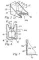
In den Figuren 1 bis 4 ist ein Schaltarm 1 dargestellt. Der Schaltarm 1 ist ein flaches aus 2mm dünnem Blech spanlos geformtes Umformteil. Das Umformteil ist gabelförmig, ausgebildet und weist zwei zinkenförmige Vorsprünge 2 und 3 auf. Die Vorsprünge 2 und 3 begrenzen eine Ausnehmung 4. Die Ausnehmung 4 ist teilweise durch vier einander gegenüberliegende Anlaufflächen 2a, 2b, 3a, 3b begrenzt. An den Anlaufflächen 2a und 3a läuft ein nicht dargestellter Schaltfinger an. Die einander gegenüberliegend ausgebildeten Anlaufflächen 2b und 3b sind in einer Sperrstellung ein Anschlag für einen nicht dargestellten Sperrzylinder bzw. Sperrbolzen. Jede der Anlaufflächen 2a, 2b, 3a, 3b ist an einem die Ausnehmung 4 säumenden und von dem Blech des Schaltarms 1 bzw. der Vorsprünge 2 und 3 abgewinkelten Abschnitt 1b ausgeformt. Die Anlaufflächen 2a und 3a weisen zueinander und sind planparallel zueinander ausgerichtet. Der lichte Abstand D zwischen den Anlaufflächen 2a und 3a ist durch spanloses Umformen mit einer Genauigkeit ausgeführt, die eine Abweichung vom Sollwert des Abstandes von maximal 1/10 mm zulässt.In the figures 1 to 4, a
Eine die Kontur der Ausnehmung 4 einseitig begrenzende Körperkante 5 grenzt die Anlaufflächen 2a, 2b, 3a, 3b (Figur 4) zu einer hinteren Mantelfläche 6 des Schaltarms ab. Die Körperkante 5 ist auf Höhe der Anlaufflächen 2a und 3a durch das Umformen abgerundet. Die Abrundung weist einen Radius auf, der kleiner als die Wandstärke des Schaltarms 1 in dem Bereich der Anschlagflächen 2a und 3a ist. Zu der anderen, der hinteren Mantelfläche 6 und damit der Körperkante 5, gegenüberliegenden flachen Seite des Schaltarms 1 mit der vorderen Mantelfläche 7 sind die Anlaufflächen 2a und 3a durch eine weitere Körperkante 8 abgegrenzt. Diese Körperkante 8 weist zumindest auf Höhe der Anlauffläche 2a eine Fase 8a und auf Höhe der Anlauffläche 3a eine Fase 8b auf. Der die Fase 8a im Querschnitt (Figur 4) zusammen mit dem Winkel α1 beschreibende Abstand d1 von der Kante 8c bis zu einer parallel zu der Kante 8c ausgerichteten gedachten gemeinsamen Schnittkante 9 ist mit einer Genauigkeit ausgeführt, die eine Abweichung des Sollwertes von maximal 1/10 mm zulässt. Die Kante 8c grenzt die Anlauffläche 2a zur Fase 8a ab. Die Schnittkante 9 ist eine Schnittkante, die eine gedachte und nicht von einer Fase gebrochene Körperkante zwischen der Anlauffläche 2a und der vorderen Mantelfläche 7 bilden würde. Der die Fase 8b im Querschnitt (Figur 4) zusammen mit dem Winkel α2 beschreibende Abstand d2 von der Kante 8d: bis zu einer parallel zu der Kante 8d ausgerichteten und gedachten gemeinsamten Schnittkante 9a ist, ebenso wie der Abstand d1, mit einer Genauigkeit ausgeführt, die eine Abweichung des Sollwertes von maximal 1/10 mm zulässt. Dabei ist die Kante 8d eine die Anlauffläche 3a zur Fase 8b begrenzende Kante. Die Schnittkante 9a ist eine parallel zu der Kante 8d ausgerichtete Schnittkante, die eine gedachte und nicht von einer Fase gebrochene Körperkante zwischen der Anschlagfläche 3a und der vorderen Mantelfläche 7 bilden würde.A
Der Schaltarm 1 ist an seinem Umriss mit einem aus abgewinkeltem Blech des Schaltarmes 1 gebildeten Rand 1a gegen unzulässige Verformungen unter Last verstärkt. Weiterhin weist der Schaltarm 1 eine sickenartig ausgebildete Ausformung 10 auf, die ebenfalls zu einer hohe Steifigkeit des Blechteils führt.The switching
Von dem Schaltarm 1 geht eine Lasche 11 ab, die für die Befestigung des Schaltarmes an einem zu seiner Längsmittelachse beweglichen Schaltelement vorgesehen ist. In Figur 13 ist beispielsweise dargestellt, wie der Schaltarm 1 mittels der Lasche 11 an dem Führungsauge 12a einer Schaltgabel 12 befestigt ist. Die Lasche 11 ist der Form des Führungsauges 12a angepasst abgerundet gebogen und ist an dem Führungsauge 12a anliegend mit dem Führungsauge 12a verschweißt.From the
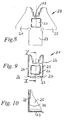
In Figur 5 bis Figur 7 ist ein weiteres Ausführungsbeispiel der Erfindung dargestellt. Ein Schaltarm 13 ist ein Umformteil aus dünnem Blech mit einer konsolenförmigen Gestalt. Der Schaltarm 13 ist aus einem ersten Wandabschnitt 14 und drei weiteren Wandabschnitten 15, 16 und 17 gebildet. Die drei Wandabschnitte 15, 16 und 17 gehen, einteilig mit dem ersten Wandabschnitt 14 ausgebildet, rechtwinklig sowie in die gleiche Richtung weisend von dem ersten Wandabschnitt 14 ab und sind auch untereinander an den Ecken 18 und 19 einstückig miteinander verbunden. Der Wandabschnitt 15 funktioniert als eine Stützplatte des Schaltarms 13, an dem sich der erste Wandabschnitt 14 bei Belastung, durch z. B. nicht dargestellte Schaltfinger, über die als Knotenbleche funktionierenden Wandabschnitte 16 und 17 abstützt. Für die Verankerung des Schaltarmes 13 an einem nicht dargestellten Schaltelement, wie z. B. einer Schaltgabel oder einer Schaltwelle, ist eine aus dem Wandabschnitt 15 hervorstehende Lasche 15a vorgesehen. Der erste Wandabschnitt 14 weist eine sickenartig ausgebildete Ausformung 20 auf, die wie die Wandabschnitte 16 und 17 zu einer hohen Steifigkeit des Blechteiles führt.In Figure 5 to Figure 7, another embodiment of the invention is shown. A switching arm 13 is a forming part of thin sheet metal with a console-like shape. The switching arm 13 is formed from a first wall section 14 and three
Der erste Wandabschnitt 14 ist mit einer zu dem freien Rand des Wandabschnittes 14 geöffneten maulförmigen Ausnehmung 14a versehen. Die Ausnehmung 14a ist an ihrem umlaufenden Rand 14b mit von dem flachen Wandabschnitt 14 abgewinkelten Blech gesäumt. In das Blech des Randes 14a sind jeweils spanlos Anlaufflächen 14c und 14d eingeformt. Die Anlaufflächen 14c und 14d liegen sich an der Ausnehmung 14a einander gegenüber und sind parallel zueinander ausgerichtet. Der Abstand D zwischen den Anlaufflächen 14c und 14d ist durch Kaltumformen von Blech mit einer Genauigkeit ausgeführt, die ein Abweichen des Abstandes D von seinem Sollwert von maximal 1/10 mm zulässt.The first wall section 14 is provided with a mouth-shaped recess 14a which is open to the free edge of the wall section 14. The recess 14a is lined at its
Die Figuren 9 und 10 zeigen eine alternative Ausbildung eines Schaltarmes 21 zu dem Schaltarm nach Figur 5. Der Schaltarm 21 ist aus einem ersten Wandabschnitt 22 und drei weiteren Wandabschnitten 23, 24 und 25 gebildet. Figur 8 zeigt den unfertigen Schaltarm 21 in Form eines teilweise am Schaltmaul umgeformten Zuschnittes 28. Die an diesem Zuschnitt 28 in der Ebene des Wandabschnittes 22 flach ausgestreckt vorliegenden Wandabschnitte 23, 24 und 25 sind einteilig mit dem Wandabschnitt 22 verbunden. Am fertigen Schaltarm 21 (Figur 9 und Figur 10) sind die Wandabschnitte 23, 24 und 25 rechtwinklig sowie die gleiche Richtung weisend von dem ersten Wandabschnitt 22 abgekantet. An den Ecken 26 und 27 sind die Wandabschnitte 23 und 24 bzw. 23 und 25 zusammengeführt und miteinander verschweißt.Figures 9 and 10 show an alternative embodiment of a switching
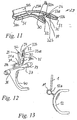
Die Figuren 11 und 12 zeigen einen Schaltarm 29. Der Schaltarm 29 ist ein im Wesentlichen flach ausgebildetes Umformteil aus dünnem Blech. Der Schaltarm 29 ist in seiner Hauptebene abgewinkelt in zwei Schenkeln 30 und 31 verlaufend ausgeführt. Der Schenkel 30 ist an seinem freien Ende gabelförmig ausgebildet und weist zwei zinkenförmige Vorsprünge 32 und 33 auf. Die Vorsprünge 32 und 33 begrenzen eine Ausnehmung 34. Die Ausnehmung 34 ist teilweise durch vier einander gegenüberliegende Anschlagflächen 32a, 32b, 33a, 33b für einen nicht dargestellten Schaltfinger begrenzt. Die einander gegenüberliegend ausgebildeten Anschlagflächen 32b und 33b sind in einer Sperrstellung ein Anschlag für einen nicht dargestellten Sperrzylinder bzw. Sperrbolzen. Jede der Anschlagflächen 32a, 32b, 33a, 33b ist an einem die Ausnehmung 34 säumenden und von dem Blech des Schaltarmes 29 abgewinkelten Abschnitt 29a ausgeformt. Die Anschlagflächen 32a und 33a weisen zueinander und ihre Oberfläche ist von den Körperkanten 35 und 36 ausgehend zur Mitte der jeweiligen Anschlagfläche 32a und 33a leicht nach außen in die Ausnehmung 34 hinein ausgewölbt geformt.Figures 11 and 12 show a switching
Der Schaltarm 29 ist an seinem Umriss mit einem aus abgewinkelten Blech des Schaltarms 29 gebildeten Rand 29b gegen unzulässige Verformung unter Last verstärkt. Weiterhin weist der Schaltarm 29 eine sickenartig ausgebildete Ausformung 31a an dem Schenkel 31 sowie eine sickenartige Ausformung 30a an dem Schenkel 30 auf, die ebenfalls zu einer hohen Steifigkeit des Blechteils führen. Von dem Schaltarm 29 geht eine Lasche 31b ab, die für die Befestigung des Schaltarms 29 an einem zu seiner Längsmittelachse beweglichen Schaltelement vorgesehen ist.The switching
In Figur 12 ist dargestellt, wie der Schaltarm 29 beispielsweise mittels der Lasche 31b an einer Schaltstange 37 befestigt ist. Die Lasche 31b ist der Form des zylindrischen Außenmantels der Schaltstange 37 angepasst abgerundet gebogen und an der Schaltstange 37 anliegend mit der Schaltstange 37 verschweißt. An der Schaltstange 37 ist eine Schaltgabel 40 befestigt. Die Schaltstange 37 ist mittels Lagern 38 und 39 entlang ihrer Längsmittelachse verschiebbar und um ihre Längsmittelachse schwenkbar in einem nicht dargestellten Getriebe gelagert.FIG. 12 shows how the switching
- 11
- Schaltarmshifting
- 1a1a
- Randedge
- 1b1b
- Abschnittsection
- 22
- Vorsprunghead Start
- 2a2a
- Anlaufflächeapproach surface
- 2b2 B
- Anlaufflächeapproach surface
- 33
- Vorsprunghead Start
- 3a3a
- Anlaufflächeapproach surface
- 3b3b
- Anlaufflächeapproach surface
- 44
- Ausnehmungrecess
- 55
- Körperkantebody edge
- 66
- hintere Mantelflächerear lateral surface
- 77
- vordere Mantelflächefront lateral surface
- 88th
- Körperkantebody edge
- 8a8a
- Fasechamfer
- 8b8b
- Fasechamfer
- 8c8c
- Kanteedge
- 8d8d
- Kanteedge
- 99
- Schnittkantecutting edge
- 9a9a
- Schnittkantecutting edge
- 1010
- Ausformungformation
- 1111
- Lascheflap
- 1212
- Schaltgabelshift fork
- 12a12a
- FührungsaugeDominant eye
- 1313
- Schaltarmshifting
- 13a13a
- Abschnittsection
- 1414
- erster Wandabschnittfirst wall section
- 14a14a
- Ausnehmung:recess:
- 14b14b
- Randedge
- 14c14c
- Anlaufflächeapproach surface
- 14d14d
- Anlaufflächeapproach surface
- 1515
- weiterer Wandabschnittanother wall section
- 15a15a
- Lascheflap
- 1616
- weiterer Wandabschnittanother wall section
- 1717
- weiterer Wandabschnittanother wall section
- 1818
- Eckecorner
- 1919
- Eckecorner
- 2020
- Ausformungformation
- 2121
- Schaltarmshifting
- 2222
- erster Wandabschnittfirst wall section
- 2323
- weiterer Wandabschnittanother wall section
- 2424
- weiterer Wandabschnittanother wall section
- 2525
- weiterer Wandabschnittanother wall section
- 2626
- Eckecorner
- 2727
- Eckecorner
- 2828
- Zuschnittcut
- 2929
- Schaltarmshifting
- 29a29a
- Abschnittsection
- 29b29b
- Randedge
- 3030
- Schenkelleg
- 30a30a
- Ausformung.Formation.
- 3131
- Schenkelleg
- 31a31a
- Ausformungformation
- 31b31b
- Lascheflap
- 3232
- Vorsprunghead Start
- 32a32a
- Anlaufflächeapproach surface
- 32b32b
- Anlaufflächeapproach surface
- 3333
- Vorsprunghead Start
- 33a33a
- Anlaufflächeapproach surface
- 33b33b
- Anlaufflächeapproach surface
- 3434
- Ausnehmungrecess
- 3535
- Körperkantebody edge
- 3636
- Körperkantebody edge
- 3737
- Schaltstangeshift rod
- 3838
- Lagercamp
- 3939
- Lagercamp
- 4040
- Schaltgabelshift fork
Claims (20)
- Gearshift arm (1, 13, 21, 29) out of sheet metal for transmitting gear shifting movements, said gearshift arm (1, 13, 21, 29) being a shaped part made without chip removal out of thin sheet metal and comprising a recess (4, 14a, 34) that is open in a mouth-shape towards an edge of the gearshift arm (1, 13, 21, 29) for engagement of a gearshift finger, characterised in that the sheet metal at the edge of the recess (4, 14a, 34) is bent at an angle.
- Gearshift arm according to claim 1, characterised in that, in its initial state prior to shaping of the gearshift arm (1, 13, 21, 29), the sheet metal has a thickness of up to 2 mm.
- Gearshift arm according to claim 1, characterised in that the material of the gearshift arm (1, 13, 21, 29) is a deep-drawing steel.
- Gearshift arm according to claim 1, characterised in that the material of the gearshift arm (1, 13, 21, 29) is a low alloy deep-drawing steel.
- Gearshift arm according to claim 1, characterised in that the gearshift arm (1, 13, 21, 29) is connected by suitable welding methods to a gearshift element that is displaceable along it central longitudinal axis.
- Gearshift rod (37) that is displaceable along its central longitudinal axis and can pivot about its central longitudinal axis, with a gearshift arm according to claim 1.
- Gearshift fork (12) with a gearshift arm according to claim 1.
- Gearshift arm according to claim 1, characterised in that the recess (4, 14a, 34) is defined at least partially by at least two stop surfaces (2a, 2b, 3a, 3b, 14c, 14d, 32a, 32b, 33a, 33b) that are situated opposite each other and are oriented towards each other.
- Gearshift arm according to claim 1, characterised in that the recess (4, 14a) is defined at least partially by at least two parallel-faced stop surfaces (2a, 2b, 14c, 14d) that are shaped without chip removal while being situated opposite each other and oriented towards each other on at least one angled section (1 b, 13a) of the sheet metal.
- Gearshift arm according to claim 1, characterised in that the recess (4, 14a) is defined at least partially by at least two parallel-faced stop surfaces (2a, 2b, 14c, 14d) that are shaped without chip removal while being situated opposite each other and oriented towards each other on angled sections (1b, 13a) of the sheet metal, the distance between the stop surfaces (2a, 2b, 14c, 14d) situated opposite each other being realised without chip removal with a precision that permits a maximum deviation of 1/10 mm from the desired value of the distance.
- Gearshift arm according to claim 1, characterised in that the recess (4) is defined at least partially by at least two stop surfaces (2a, 3a) that are shaped without chip removal while being situated opposite each other and oriented towards each other, said stop surface (2a, 3a) merging at least on one side with a body edge (5) that is rounded without chip removal.
- Gearshift arm according to claim 1, characterised in that the recess (4) is defined at least partially by at least two stop surfaces (2a, 3a) that are shaped without chip removal while being situated opposite each other and oriented towards each other on at least one angled section (1b) of the sheet metal, said gearshift arm (1) comprising at least one body edge (8) having a bevel (8a, 8b) integrally formed thereon without chip removal, which body edge (8) separates the stop surface (2a, 3a) from an outer surface (7) of the gearshift arm (1) at least on one side.
- Gearshift arm according to claim 1, characterised in that the recess (4) is defined at least partially by at least two stop surfaces (2a, 3a) that are shaped without chip removal while being situated opposite each other and oriented towards each other on at least one angled section (1b) of the sheet metal, said gearshift arm (1) comprising at least one body edge (8) having a bevel (8a, 8b) integrally formed thereon without chip removal, which body edge (8) separates the stop surface (2a, 3a) from an outer surface (7) of the gearshift arm (1) at least on one side, and a distance describing the bevel (8a, 8b) in the cross-section of the gearshift arm (1) between an edge (8c, 8d) that limits the stop surface (2a, 3a) in the direction of the bevel (8a, 8b) and, parallel to the edge (8c, 8d), an imaginary, common intersecting edge (9, 9a) of the stop surface (2a, 3a) prolonged beyond the bevel (8a, 8b) with the outer surface (7) of the gearshift arm (1) prolonged beyond the bevel (8a, 8b) possesses a precision that permits a maximum deviation of 1/10 mm from the desired value of the distance.
- Gearshift arm according to claim 1, characterised in that the shaped part has a bifurcated configuration at one end and this end comprises two projections (2, 3, 32, 33) in the form of fork arms and further comprises at least one edge (1a, 29b) formed by angled sheet metal, and each of the projections (2, 3, 32, 33) comprises on an angled section (1b, 29a) at least one stop surface (2a, 2b, 3a, 3b, 32a, 32b, 33a, 33b) that is situated opposite another stop surface (2a, 2b, 3a, 3b, 32a, 32b, 33a, 33b) on the other of the projections (2, 3, 32, 33).
- Gearshift arm according to claim 14, characterised in that the gearshift arm (1, 29) comprises at least one tab (11, 31b) that starts from the gearshift arm (1, 29), and the gearshift arm (1, 29) is connected to a gearshift element by means of at least one weld joint on the tab (11, 31b).
- Gearshift arm according to claim 14, characterised in that the gearshift arm (1, 29) is provided with at least one bead-like shaped portion (10, 31a, 30a) in the sheet material.
- Gearshift arm according to claim 1, characterised in that the gearshift arm (13, 21) is a bracket-like shaped part, the gearshift arm (13, 21) comprises a first wall section (14, 22) having a mouth-shaped recess (14a) that is open towards an edge of the gearshift arm (13, 21) for engagement of a gearshift finger, the recess (14a) is defined at least partially by at least two stop surfaces (14c, 14d) that are shaped without chip removal while being situated opposite each other and oriented towards each other on angled sections (13a) of the sheet metal, and the first wall section (14) merges integrally with three further wall sections (15, 16, 17) that are bent at an angle from the first wall section (14) and point in the same direction.
- Gearshift arm according to claim 17, characterised in that the three further wall sections (15, 16, 17) are configured in one piece with one another.
- Gearshift arm according to claim 17, characterised in that the three further wall sections (23, 24, 25) are folded from the first wall section (22) and every two of the further wall sections (23, 24, 25) are fixed to each other.
- Gearshift arm according to claim 17, characterised in that the gearshift arm (13, 21) is provided with at least one bead-like shaped part (20) in the sheet material.
Applications Claiming Priority (3)
| Application Number | Priority Date | Filing Date | Title |
|---|---|---|---|
| DE10148980A DE10148980A1 (en) | 2001-10-04 | 2001-10-04 | Switch arm, for the transmission of switching movements, is of a deep drawn plate to give material and production cost savings |
| DE10148980 | 2001-10-04 | ||
| PCT/EP2002/010915 WO2003031848A1 (en) | 2001-10-04 | 2002-09-28 | Shifting arm |
Publications (2)
| Publication Number | Publication Date |
|---|---|
| EP1432935A1 EP1432935A1 (en) | 2004-06-30 |
| EP1432935B1 true EP1432935B1 (en) | 2007-06-06 |
Family
ID=7701381
Family Applications (1)
| Application Number | Title | Priority Date | Filing Date |
|---|---|---|---|
| EP02800581A Expired - Fee Related EP1432935B1 (en) | 2001-10-04 | 2002-09-28 | Shifting arm |
Country Status (5)
| Country | Link |
|---|---|
| US (3) | US20040187623A1 (en) |
| EP (1) | EP1432935B1 (en) |
| BR (1) | BR0206095A (en) |
| DE (2) | DE10148980A1 (en) |
| WO (1) | WO2003031848A1 (en) |
Families Citing this family (7)
| Publication number | Priority date | Publication date | Assignee | Title |
|---|---|---|---|---|
| DE10202651B4 (en) * | 2002-01-23 | 2014-01-23 | Koki Technik Transmission Systems Gmbh | transmission |
| DE10326870B3 (en) * | 2003-06-14 | 2005-02-03 | Dieter Kirschdorf | Method for producing a gear shift element made of metal |
| GB2476072B (en) * | 2009-12-10 | 2017-02-01 | Gm Global Tech Operations Llc | Gearbox |
| CN206102165U (en) * | 2016-07-13 | 2017-04-19 | 革新(厦门)运动器材有限公司 | Folding bed |
| US10835048B2 (en) | 2016-08-31 | 2020-11-17 | Inno-Sports Co., Ltd. | Connection member and folding bed having same |
| US10738887B2 (en) * | 2018-02-06 | 2020-08-11 | Arvinmeritor Technology, Llc | Shift fork and method of manufacture |
| CN115157253A (en) * | 2022-07-13 | 2022-10-11 | 陕西法士特齿轮有限责任公司 | Method, system, device, equipment and storage medium for assembling outer gear shifting arm of transmission |
Family Cites Families (23)
| Publication number | Priority date | Publication date | Assignee | Title |
|---|---|---|---|---|
| DE1122385B (en) * | 1960-06-28 | 1962-01-18 | Opel Adam Ag | Shift fork made of sheet metal for speed change transmissions, especially of motor vehicles |
| DE1848789U (en) * | 1961-06-29 | 1962-03-22 | Bosch Gmbh Robert | FORK-SHAPED SWIVEL LEVER, IN PARTICULAR FOR ENGAGING THE PINION GEAR OF TURNING MOTORS FOR COMBUSTION MACHINES. |
| DE2528905C3 (en) * | 1975-06-28 | 1979-08-02 | Audi Nsu Auto Union Ag, 7107 Neckarsulm | Process for the production of metallic rings |
| US4259877A (en) * | 1979-07-16 | 1981-04-07 | Dana Corporation | Transmission shift control |
| US4793202A (en) * | 1984-10-09 | 1988-12-27 | Honda Giken Kogyo Kabushiki Kaisha | Vehicular transmission shift mechanism |
| US5189402A (en) * | 1987-05-14 | 1993-02-23 | Advanced Interaction, Inc. | Content addressable video system for image display |
| US5487318A (en) * | 1994-12-01 | 1996-01-30 | New Holland North America, Inc. | Shift fork actuated position sensor |
| GB9607194D0 (en) * | 1996-04-04 | 1996-06-12 | Eaton Corp | Improved single shaft shifting mechanism |
| FR2762659B1 (en) * | 1997-04-25 | 1999-06-25 | Peugeot | SLIDING GEARBOX FORK AND ARRANGEMENT OF THIS FORK ON A SOLIDARITY AXIS OF A SHEET FORK |
| GB2326203B (en) * | 1997-05-15 | 2001-12-19 | Sagar Richards Ltd | Improvements in or relating to selector forks |
| US5958603A (en) * | 1997-06-09 | 1999-09-28 | Atd Corporation | Shaped multilayer metal foil shield structures and method of making |
| US6038938A (en) * | 1997-10-14 | 2000-03-21 | New Venture Gear, Inc. | Shift fork/gate assembly |
| DE69841843D1 (en) * | 1997-12-09 | 2010-09-30 | Isuzu Motors Ltd | TRANSMISSION |
| DE19757184A1 (en) * | 1997-12-22 | 1999-06-24 | Schaeffler Waelzlager Ohg | Switch fork for motor vehicle gearbox |
| FR2778444B1 (en) * | 1998-05-05 | 2000-06-23 | Renault | COMPACT GEARBOX |
| FR2782768B1 (en) * | 1998-09-02 | 2000-11-03 | Coutier Moulage Gen Ind | METHOD OF MANUFACTURING A GEARBOX FORK AND FORK THUS OBTAINED |
| DE19845146A1 (en) * | 1998-10-01 | 2000-04-13 | Progress Werk Oberkirch Ag | Method for producing a cross member and such cross members |
| JP3170257B2 (en) * | 1999-02-22 | 2001-05-28 | 本田技研工業株式会社 | Transmission gearshift mechanism |
| DE19919271B4 (en) * | 1999-04-28 | 2009-04-30 | Schaeffler Kg | Rocker arm for a change-speed gearbox |
| DE10045506B4 (en) * | 1999-09-14 | 2011-07-21 | ISE Automotive GmbH, 51702 | Method for producing a shift fork for use in transmissions, esp. In car transmissions |
| DE19944323A1 (en) * | 1999-09-15 | 2000-11-02 | Daimler Chrysler Ag | Bicycle derailleur gear shifter comprizes fork with formed part central between fork ends riding sleeve groove with play before contact. |
| DE10018850A1 (en) * | 2000-04-14 | 2001-10-18 | Schaeffler Waelzlager Ohg | Gear shift fork, comprising two identical halves, reinforced by collars surrounding rims completely |
| US6615635B2 (en) * | 2000-06-20 | 2003-09-09 | Ina Walzlager Schaeffler Ohg | Method of making a lever-type cam follower, and lever-type cam follower |
-
2001
- 2001-10-04 DE DE10148980A patent/DE10148980A1/en not_active Withdrawn
-
2002
- 2002-09-28 WO PCT/EP2002/010915 patent/WO2003031848A1/en active IP Right Grant
- 2002-09-28 EP EP02800581A patent/EP1432935B1/en not_active Expired - Fee Related
- 2002-09-28 DE DE50210286T patent/DE50210286D1/en not_active Expired - Lifetime
- 2002-09-28 BR BR0206095-7A patent/BR0206095A/en not_active IP Right Cessation
-
2004
- 2004-04-05 US US10/818,247 patent/US20040187623A1/en not_active Abandoned
-
2006
- 2006-05-26 US US11/441,637 patent/US20060213312A1/en not_active Abandoned
-
2007
- 2007-12-05 US US11/951,118 patent/US20080083296A1/en not_active Abandoned
Also Published As
| Publication number | Publication date |
|---|---|
| US20080083296A1 (en) | 2008-04-10 |
| WO2003031848A1 (en) | 2003-04-17 |
| EP1432935A1 (en) | 2004-06-30 |
| US20040187623A1 (en) | 2004-09-30 |
| BR0206095A (en) | 2003-10-28 |
| DE50210286D1 (en) | 2007-07-19 |
| US20060213312A1 (en) | 2006-09-28 |
| DE10148980A1 (en) | 2003-04-10 |
Similar Documents
| Publication | Publication Date | Title |
|---|---|---|
| EP2212571B1 (en) | Thrust washer and radial/axial bearing having such a thrust washer | |
| WO2003042023A1 (en) | Force strut brace | |
| WO2005113945A1 (en) | Oil chamber sealing unit of a swing-wing adjuster of a camshaft pertaining to an internal combustion engine | |
| EP1969259B1 (en) | Shift arrangement having a shift fork | |
| EP1432935B1 (en) | Shifting arm | |
| DE10309407A1 (en) | Shifter fork with a fork-shaped body made of sheet metal | |
| EP1225375A2 (en) | Gear shift cam for transmission | |
| DE102015204087B4 (en) | bearing device | |
| EP1064467B1 (en) | Universal joint yoke | |
| DE10044732A1 (en) | Roller tappet for an internal combustion engine | |
| AT510864B1 (en) | TRANSMISSION ELEMENT FOR ACTUATING A SWITCHING ELEMENT AND SWITCHING DEVICE | |
| EP1757847B1 (en) | Shift fork and associated manufacturing method | |
| WO1999025958A1 (en) | Cam follower formed without removing any material | |
| DE102006001229B4 (en) | Shift fork assembly for automotive manual transmission | |
| EP4111074A1 (en) | Centrifugal pendulum having a roller track projecting axially outward, and torque transmission device | |
| EP1746312B1 (en) | Actuating device for an selector sleeve | |
| EP2507536B1 (en) | Shifting element for a manual transmission | |
| DE102013224848A1 (en) | Rocker arm for a valve train of an internal combustion engine and method for producing a rocker arm | |
| DE102012208788A1 (en) | Sheet metal rocking lever for valve drive of internal combustion engine, has crossbeam that connects side walls with pivotable support of axis, where side wall height is implemented at load section at through-holes in ratio to lever width | |
| AT509997B1 (en) | SWITCHING DEVICE FOR A GEAR CHANGING GEAR | |
| EP2268946B1 (en) | Gear-shifting drum having a guide-rib arrangement | |
| WO2009015964A1 (en) | Gear component and method for producing said gear component | |
| DE102004037690B3 (en) | Sheet metal rolled sleeve has caulked gap in press fitting joining two ends for e.g. automotive running gear | |
| EP3228402B1 (en) | Method for producing a component having at least one overhang | |
| DE10024552A1 (en) | Cam and bearing elements for composite camshafts |
Legal Events
| Date | Code | Title | Description |
|---|---|---|---|
| PUAI | Public reference made under article 153(3) epc to a published international application that has entered the european phase |
Free format text: ORIGINAL CODE: 0009012 |
|
| 17P | Request for examination filed |
Effective date: 20040211 |
|
| AK | Designated contracting states |
Kind code of ref document: A1 Designated state(s): AT BE BG CH CY CZ DE DK EE ES FI FR GB GR IE IT LI LU MC NL PT SE SK TR |
|
| AX | Request for extension of the european patent |
Extension state: AL LT LV MK RO SI |
|
| RAP1 | Party data changed (applicant data changed or rights of an application transferred) |
Owner name: SCHAEFFLER KG |
|
| 17Q | First examination report despatched |
Effective date: 20060828 |
|
| GRAP | Despatch of communication of intention to grant a patent |
Free format text: ORIGINAL CODE: EPIDOSNIGR1 |
|
| GRAS | Grant fee paid |
Free format text: ORIGINAL CODE: EPIDOSNIGR3 |
|
| GRAA | (expected) grant |
Free format text: ORIGINAL CODE: 0009210 |
|
| AK | Designated contracting states |
Kind code of ref document: B1 Designated state(s): CZ DE FR IT |
|
| REF | Corresponds to: |
Ref document number: 50210286 Country of ref document: DE Date of ref document: 20070719 Kind code of ref document: P |
|
| ET | Fr: translation filed | ||
| PGFP | Annual fee paid to national office [announced via postgrant information from national office to epo] |
Ref country code: CZ Payment date: 20070822 Year of fee payment: 6 |
|
| PLBE | No opposition filed within time limit |
Free format text: ORIGINAL CODE: 0009261 |
|
| STAA | Information on the status of an ep patent application or granted ep patent |
Free format text: STATUS: NO OPPOSITION FILED WITHIN TIME LIMIT |
|
| 26N | No opposition filed |
Effective date: 20080307 |
|
| PGFP | Annual fee paid to national office [announced via postgrant information from national office to epo] |
Ref country code: FR Payment date: 20080915 Year of fee payment: 7 |
|
| PGFP | Annual fee paid to national office [announced via postgrant information from national office to epo] |
Ref country code: IT Payment date: 20080927 Year of fee payment: 7 |
|
| PG25 | Lapsed in a contracting state [announced via postgrant information from national office to epo] |
Ref country code: CZ Free format text: LAPSE BECAUSE OF NON-PAYMENT OF DUE FEES Effective date: 20080928 |
|
| REG | Reference to a national code |
Ref country code: FR Ref legal event code: ST Effective date: 20100531 |
|
| PG25 | Lapsed in a contracting state [announced via postgrant information from national office to epo] |
Ref country code: FR Free format text: LAPSE BECAUSE OF NON-PAYMENT OF DUE FEES Effective date: 20090930 |
|
| PG25 | Lapsed in a contracting state [announced via postgrant information from national office to epo] |
Ref country code: IT Free format text: LAPSE BECAUSE OF NON-PAYMENT OF DUE FEES Effective date: 20090928 |
|
| REG | Reference to a national code |
Ref country code: DE Ref legal event code: R081 Ref document number: 50210286 Country of ref document: DE Owner name: SCHAEFFLER TECHNOLOGIES AG & CO. KG, DE Free format text: FORMER OWNER: SCHAEFFLER TECHNOLOGIES GMBH & CO. KG, 91074 HERZOGENAURACH, DE Effective date: 20120828 Ref country code: DE Ref legal event code: R081 Ref document number: 50210286 Country of ref document: DE Owner name: SCHAEFFLER TECHNOLOGIES GMBH & CO. KG, DE Free format text: FORMER OWNER: SCHAEFFLER TECHNOLOGIES GMBH & CO. KG, 91074 HERZOGENAURACH, DE Effective date: 20120828 |
|
| REG | Reference to a national code |
Ref country code: DE Ref legal event code: R081 Ref document number: 50210286 Country of ref document: DE Owner name: SCHAEFFLER TECHNOLOGIES GMBH & CO. KG, DE Free format text: FORMER OWNER: SCHAEFFLER TECHNOLOGIES AG & CO. KG, 91074 HERZOGENAURACH, DE Effective date: 20140218 Ref country code: DE Ref legal event code: R081 Ref document number: 50210286 Country of ref document: DE Owner name: SCHAEFFLER TECHNOLOGIES AG & CO. KG, DE Free format text: FORMER OWNER: SCHAEFFLER TECHNOLOGIES AG & CO. KG, 91074 HERZOGENAURACH, DE Effective date: 20140218 |
|
| REG | Reference to a national code |
Ref country code: DE Ref legal event code: R081 Ref document number: 50210286 Country of ref document: DE Owner name: SCHAEFFLER TECHNOLOGIES AG & CO. KG, DE Free format text: FORMER OWNER: SCHAEFFLER TECHNOLOGIES GMBH & CO. KG, 91074 HERZOGENAURACH, DE Effective date: 20150211 |
|
| PGFP | Annual fee paid to national office [announced via postgrant information from national office to epo] |
Ref country code: DE Payment date: 20171130 Year of fee payment: 16 |
|
| REG | Reference to a national code |
Ref country code: DE Ref legal event code: R119 Ref document number: 50210286 Country of ref document: DE |
|
| PG25 | Lapsed in a contracting state [announced via postgrant information from national office to epo] |
Ref country code: DE Free format text: LAPSE BECAUSE OF NON-PAYMENT OF DUE FEES Effective date: 20190402 |
|
| P01 | Opt-out of the competence of the unified patent court (upc) registered |
Effective date: 20230522 |