EP1432006A2 - Energy filter and electron microscope - Google Patents
Energy filter and electron microscope Download PDFInfo
- Publication number
- EP1432006A2 EP1432006A2 EP03257956A EP03257956A EP1432006A2 EP 1432006 A2 EP1432006 A2 EP 1432006A2 EP 03257956 A EP03257956 A EP 03257956A EP 03257956 A EP03257956 A EP 03257956A EP 1432006 A2 EP1432006 A2 EP 1432006A2
- Authority
- EP
- European Patent Office
- Prior art keywords
- filter
- energy
- energy filter
- optical axis
- filters
- Prior art date
- Legal status (The legal status is an assumption and is not a legal conclusion. Google has not performed a legal analysis and makes no representation as to the accuracy of the status listed.)
- Granted
Links
- 230000004075 alteration Effects 0.000 claims abstract description 26
- 230000003287 optical effect Effects 0.000 claims abstract description 23
- 239000002245 particle Substances 0.000 claims description 16
- 239000006185 dispersion Substances 0.000 claims description 8
- 238000010894 electron beam technology Methods 0.000 abstract description 63
- 238000010586 diagram Methods 0.000 description 11
- 238000009826 distribution Methods 0.000 description 9
- 230000001133 acceleration Effects 0.000 description 7
- 230000000694 effects Effects 0.000 description 7
- 238000000034 method Methods 0.000 description 6
- 241000220317 Rosa Species 0.000 description 5
- 230000003993 interaction Effects 0.000 description 3
- 201000009310 astigmatism Diseases 0.000 description 2
- 230000005540 biological transmission Effects 0.000 description 2
- 230000005684 electric field Effects 0.000 description 1
- 238000003384 imaging method Methods 0.000 description 1
- 239000000696 magnetic material Substances 0.000 description 1
- 238000001000 micrograph Methods 0.000 description 1
- 230000000979 retarding effect Effects 0.000 description 1
Images




Classifications
-
- H—ELECTRICITY
- H01—ELECTRIC ELEMENTS
- H01J—ELECTRIC DISCHARGE TUBES OR DISCHARGE LAMPS
- H01J37/00—Discharge tubes with provision for introducing objects or material to be exposed to the discharge, e.g. for the purpose of examination or processing thereof
- H01J37/02—Details
- H01J37/04—Arrangements of electrodes and associated parts for generating or controlling the discharge, e.g. electron-optical arrangement or ion-optical arrangement
- H01J37/05—Electron or ion-optical arrangements for separating electrons or ions according to their energy or mass
-
- H—ELECTRICITY
- H01—ELECTRIC ELEMENTS
- H01J—ELECTRIC DISCHARGE TUBES OR DISCHARGE LAMPS
- H01J37/00—Discharge tubes with provision for introducing objects or material to be exposed to the discharge, e.g. for the purpose of examination or processing thereof
- H01J37/02—Details
- H01J37/04—Arrangements of electrodes and associated parts for generating or controlling the discharge, e.g. electron-optical arrangement or ion-optical arrangement
- H01J37/153—Electron-optical or ion-optical arrangements for the correction of image defects, e.g. stigmators
Definitions
- the present invention relates to an energy filter for selectively passing charged particles having certain energies and to an electron microscope using this filter.
- the energy width of the electron beam directed at the specimen must be narrowed in order to enhance the energy resolution.
- the energy width is preferably on the order of 0.1 eV.
- the electron beam passed through the energy filter in this way is required to be achromatic, i.e., free of energy dispersion.
- the Boersch effect is a phenomenon in which the energies of electrons (generally, charged particles) traveling close to each other affect each other according to their respective speeds due to their mutual Coulomb interactions. Accordingly, where an electron beam of low energy passes through the energy filter, especially when electrons travel close to each other around the focal point within the filter, the electrons affect each other, varying their energies. This broadens their energies. Consequently, it is difficult to obtain an electron beam having a narrow energy width.
- the sole method conventionally adopted such that the energy filter placed in a position where the electron beam is not yet accelerated is free from the Boersch effect is to prevent crossover of beam electrons by astigmatic focusing.
- Fig. 8 shows the structure of a first energy filter that forms an astigmatic image. This and other figures are not drawn to scale, for convenience of illustration of the first energy filter 110.
- the first energy filter 110 has two stages of Wien filters 112 and 114 that extend in the direction of the optical axis L0, or the Z-direction.
- the filters 112 and 114 are located before and after the position of a slit 113 asymmetrically with respect to this position (see Patent Reference 1 (Japanese Patent Laid-Open No. 2001-23558), for example).
- the first energy filter 110 has a first electrostatic lens 111, the first stage of Wien filter 112, the slit 113, the second stage of Wien filter 114, and a second electrostatic lens 115 in this order as viewed along the direction of the electron beam that is emitted from an electron gun 201 and travels in the Z-direction.
- the electron beam takes an orbit (Fig. 8(b)) along the X-axis that is the dispersive direction, an orbit (Fig. 8(c)) extending in the Y-direction perpendicularly to that orbit, and a dispersive orbit (Fig. 8(d)).
- the X-direction electron beam is focused at the position of the slit 113 but the Y-direction beam is not.
- Fig. 9 shows the profile portions of the electron beam focused on the slit 113 of the first energy filter.
- the beam focused on the slit 113 assumes an elliptical form extending in the Y-direction. Because the first energy filter 110 has a dispersive direction in the X-direction, beam electrons having different energies are focused at different positions in the X-direction.
- the profile portions 117 and 118 of the beam electrons having different energies and focused at different positions in the X-direction are shown in the figure.
- the position at which the electron beam is focused can be adjusted in the Y-direction. Therefore, the ratio between the width W and height H of the profile of the electron beam on the slit 113 can be adjusted.
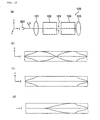
- Fig. 10 shows the structure of a second energy filter.
- the second energy filter indicated by 120, has two stages of Wien filters 122 and 124 that extend in the direction of the optical axis L0, or the Z-direction.
- the filters 122 and 124 are located before and after the position of a slit 123 symmetrically with respect to this position.
- the second energy filter 120 has a first electrostatic lens 121, the first stage of Wien filter 122, the slit 123, the second stage of Wien filter 124, and a second electrostatic lens 125 in this order as viewed along the direction of the electron beam that is emitted from an electron gun 201 and travels in the Z-direction.
- the filters 122 and 124 are symmetrical in shape with respect to the slit 123.
- the electron beam takes an orbit ((b) of Fig. 10) in the X-direction that is the dispersive direction and an orbit ((c) of Fig. 10)) extending in the Y-direction perpendicularly to that orbit.
- the orbits of the electron beam through the Wien filters 122 and 124 are symmetrical with respect to the position of the slit 123. Specifically, the orbit of the beam is inverted with respect to the focal position on the slit 123.
- the profile of the electron beam on the slit 123 is such that the height is greater than the width in the same way as in the case of the first energy filter 110.
- the ratio of the width to the height of the profile of the electron beam on the slit 123 is determined only by the incident angle of the electron beam. To prevent this ratio from becoming excessive, a well-collimated beam must be entered through a small aperture.
- the ratio of the width to the height becomes excessively large. Consequently, when energy selection is performed on the slit, the electron beam will produce greater loss or the energy width will not be reduced as expected.
- the purpose of elongating the profile of the electron beam is to reduce Coulomb interactions such as the Boersch effect. Therefore, the profile of the beam is not elongated too much. It is necessary to set the ratio to 1:2 or higher. However, a large ratio such as 1:10 is not necessary. The ratio may be set to intermediate values between them.
- the profile of the electron beam at the slit 113 can be set to a value within the range described above.
- the first energy filter 110 cannot cancel aberrations by the first and second stages of Wien filters 112 and 114 as mentioned previously. In consequence, the electron beam going out of the first energy filter 110 contains aberration.
- the aberration in the energy filter can be reduced by well designing the first stage of filter, as well as by canceling out the aberrations in the first and second stages of Wien filters 122 and 124 that are symmetrical with respect to the slit 123 as shown in the second energy filter 120.
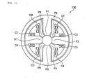
- Fig. 11 shows a Wien filter with small aberration.
- This Wien filter indicated by 130, is designed to reduce the aberration by bringing the electric field distribution in the fringing field into coincidence with the magnetic field distribution. This in turn is achieved by producing electric and magnetic fields using eight poles P1 to P8 (see, for example, Patent Reference 2 (Japanese Patent No. 3,040,245)). Also shown in the figure are coils C1 to C8. Aberration still remains, however, even if this Wien filter having the eight poles is used. Hence, there is a demand for a technique of reducing this aberration.
- the present invention is proposed in view of the foregoing circumstances. It would be desirable to provide an energy filter with smaller aberration and an electron microscope fitted with this energy filter.
- the present invention provides an energy filter having a first filter and a second filter disposed behind the first filter, the first filter using a combination of electric and magnetic fields to select charged particles having a certain energy.
- the first filter is so controlled that a beam of charged particles having a cross-sectional shape extending in a direction perpendicular to a direction in which the charged particles are dispersed in the first filter is formed between the first and second filters.
- the second filter is so controlled that aberration created by the first filter is reduced.
- Fig. 1 shows the structure of an energy filter according to an embodiment.
- the energy filter indicated by numeral 10, has a first stage of Wien filter 12, a slit 13, and a second stage of Wien filter 14 which are located in this order in the direction of travel of an electron beam along an optical axis L0.
- the electron beam is emitted from an electron gun (source of charged particles) and enters the first stage of Wien filter 12, which acts to focus the beam in one direction perpendicular to the optical axis L0.
- the Wien filters 12 and 14 are identical in shape.
- the slit 13 is located in the position where the beam is focused.
- the beam focused at the position of the slit 13 by the first stage of Wien filter 12 is made to enter the second stage of Wien filter 14.
- the second stage of Wien filter 14 is so designed that the orbit for the electron beam is inverted with respect to the focal position at the slit 13.
- the length of the second stage of Wien filter 14 as measured along the optical axis L0 is identical with that of the first stage of Wien filter 12.
- a first clamp 11 is disposed ahead of the first stage of Wien filter 12.
- a second clamp 15 is positioned behind the second stage of Wien filter 14.
- Each of the Wien filters 12 and 14 has electric and magnetic quadrupole fields along the optical axis L0, the fields being rotated through 45° about the optical axis L0. Thus, astigmatic focusing is achieved.
- the first stage of Wien filter 12 and the second stage of Wien filter 14 which are identical in shape are disposed along the optical axis L0 symmetrically with respect to the slit 13.
- the orbit of the beam is inverted with respect to the focal position on the slit 13. Accordingly, aberrations due to the Wien filters 12 and 14 are canceled out. Consequently, aberration at the focal point of the electron beam behind the energy filter 10 substantially disappears. Furthermore, astigmatic focusing is accomplished.
- Fig. 2 shows the structure of the first stage of Wien filter 12.
- the second stage of Wien filter 14 is similar in structure to the filter 12 and so its description is omitted.
- the XYZ coordinate axes are so set that the direction of the optical axis L0 along which the electron beam moves is taken as the Z-direction.
- the first stage of Wien filter 12 has first through twelfth pole pieces P1 to P12 showing 12-fold symmetry with respect to the optical axis L0.
- the pole pieces P1 to P12 are made of a magnetic material. Voltages are applied to these pole pieces. A coil is wound around each of at least four of these pole pieces.
- the pole pieces P1 to P12 are set in this order in a counterclockwise direction, for example, about the Z-axis from the X-direction.
- V2(i) be the voltage applied to the ith magnet pole piece relative to the voltage V2(1) at the first magnet pole piece P1.
- V2 (2) 2 ⁇ V2 (1)
- V2 (3) V2 (1)
- V2 (4) - V2 (1)
- V2 (5) - 2 ⁇ V2 (1)
- V2 (6) - V2 (1)
- V2 (7) V2 (1)
- V2 (8) 2 ⁇ V2 (1)
- V2 (9) V2 (1)
- V2 (10) - V2 (1)
- V2 (11) - 2 ⁇ V2 (1)
- V2 (12) - V2 (1)
- an ampere-turn (the product of the current and the number of coil turns) given by Eq. (2) is imparted to each of the pole pieces P1 to P12 to produce the magnetic quadrupole field. It is assumed here that the ampere-turn of the ith pole piece Pi is given by N I 2(i). These ampere-turns N I 2(i) are given based on the ampere-turn N I 2 (1) of the first pole piece P1.
- Fig. 3 depicts diagrams showing the potential distributions in the electric and magnetic quadrupole fields in the first stage of Wien filter 12.
- Fig. 3 (a) shows the distribution in the electric quadrupole field, and (b) shows the distribution in the magnetic quadrupole field. In these diagrams, curves indicating equipotential lines are shown.
- the twelfth pole piece P12 and the first pole piece P1 which are opposite to each other with respect to the X axis have the same polarity.
- the sixth pole piece P6 and seventh pole piece P7 are placed opposite to each other with respect to the X axis and have the same polarity.
- the third pole piece P3 and fourth pole piece P4 which are opposite to each other with respect to the Y axis have the same polarity.
- the ninth pole piece P9 and tenth pole P10 are placed opposite to each other with respect to the Y axis and have the same polarity.
- the first through third pole pieces P1 to P3 are identical in polarity with the seventh through ninth pole pieces P7 to P9, respectively.
- the fourth through sixth pole pieces P4 to P6 are identical in polarity with the tenth to twelfth pole pieces P10 to P12, respectively.
- the first and second stages of Wien filters 12 and 14 satisfy the Wien condition by electric and magnetic dipole fields.
- aberration is intentionally created on the first focus by the electric and magnetic quandrupole fields.
- E2 and B2 be the electric and magnetic quadrupole fields, respectively.
- R be the cyclotron radius.
- the electric and magnetic quadrupole fields are set to ranges given by Eqs. (5) and (6), respectively. 1 ⁇ f (E2) ⁇ 4 - 3 ⁇ g (B2) ⁇ 0
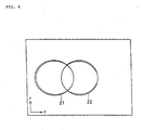
- Fig. 4 is a diagram showing examples of the profile of the electron beam focused on the slit 13 in the present embodiment.
- the left profile portion 21 is obtained by focusing of an energy-loss electron beam.
- the right profile portion 22 is obtained by focusing of an electron beam having an energy loss of 0.4 eV.
- the electron beam is shaped into substantially elliptical profile portions 21 and 22, elongated in the Y-direction.
- These elliptical profile portions 21 and 22 are produced by aberration created by electric and magnetic quadrupole fields.
- the profile portions 21 and 22 of the beam are sufficiently spaced from each other. Accordingly, the energy filter 10 according to the present embodiment achieves an energy resolution of less than 0.4 eV. Where estimated from the figure, the energy resolution is less than 0.1 eV.
- the conditions given by Eqs. (5) and (6) are added to the astigmatic focusing condition of Eq. (4).
- the conditions of Eqs. (5) and (6) induce aberration in the electron beam focused onto the slit 13, producing the profile portions 21 and 22 stretched in the Y-direction.
- the profile portions 21 and 22 stretched in the Y-direction assure high resolution.
- Fig. 5 is a diagram showing the profile portions of an electron beam focused onto the slit 13, as a reference example, in a case where the condition of Eq. (4) is satisfied but the conditions of Eqs. (5) and (6) are not.
- (a) shows a case in which only an electric quandrupole field is produced to satisfy the astigmatic focusing condition of Eq. (4).
- the method of achieving the astigmatic focusing condition of Eq. (4) using only the electric quadrupole field is implemented in an octopole Wien filter.
- the profile portions 21 and 22 of the electron beam focused on the slit 113 assume elliptical forms stretched in the X-direction, i.e., in the direction of dispersion.
- the energy resolution is less than the energy difference of 0.4 eV but does not reach 0.2 eV.
- FIG. 5 shows a case in which astigmatic focusing condition of Eq. (4) is achieved only by the quadrupole magnetic field B2.
- the method of achieving the astigmatic focusing condition of Eq. (4) only by a magnetic quadrupole field in this way is implemented by a Wien filter having tilted pole pieces.
- the profile portions 21 and 22 of the electron beam focused on the slit 13 are stretched in the X-direction, i.e., in the direction of dispersion. Since the profile portions 21 and 22 overlap, the energy resolution is lower than 0.4 eV.
- the amount of dispersion along the X-direction is almost constant irrespective of the values of the electric and magnetic quadrupole fields. Accordingly, the profile portions 21 and 22 of the electron beam on the slit 13 contribute much to the energy resolution.
- the profile portions 21 and 22 of the electron beam focused on the slit 13 are stretched in the X-direction. It can be seen, therefore, that the profile portions 21 and 22 may be stretched in the Y-direction in order to improve the energy resolution.
- Fig. 6 shows the profile portions of an electron beam focused on the slit 13 under the Rose's condition of Eq. (7) as a reference example.
- the energy filter 10 has a structure that is symmetrical with respect to the slit 13. Also, the orbit of the electron beam is symmetrical with respect to the slit 13. Consequently, aberration is suppressed. Furthermore, the profile portions 21 and 22 of the electron beam focused onto the slit 13 are stretched in the Y-direction perpendicular to the direction of dispersion, by producing electric and magnetic quadrupole fields so as to satisfy the conditions of Eqs. (5) and (6). Hence, high energy resolution is accomplished.
- Fig. 7 shows the structures of electron microscopes each incorporating the energy filter 10.
- (a) shows an example in which the energy filter is arranged between a field emission gun (FEG) and an acceleration tube.
- FEG field emission gun
- An electron beam having a relatively low energy of about 1 to several keV emitted from the FEG 51 is made to enter a decelerating energy filter 57 consisting of an entrance aperture 52, a decelerating portion 53, an energy filter portion 54, an accelerating portion 55, and an exit aperture 56.
- incident electrons are decelerated to an energy of about hundreds of eV by the decelerating portion 53 and then only electrons having a given energy are selected by the filter portion 54.
- the electrons are again accelerated to have the original energy by the accelerating portion 55, and exit from the exit aperture 56.
- the energy filter portion 54 corresponds to the energy filter 10 shown in Fig. 1.
- the electron beam exiting from the exit aperture 56 is accelerated to a desired high energy (e.g., about 200 keV) by an acceleration tube 58 and then made to hit a specimen 61 via a system of condenser lenses 59 and an objective lens 60.
- a desired high energy e.g., about 200 keV
- FIG. 7 shows an embodiment in which the energy filter according to the invention is positioned behind an acceleration tube.
- an electron beam having a relatively low energy of about 1 to several keV emitted from an FEG 51 is accelerated to a desired high energy (e.g., about 200 keV) by an acceleration tube 58 and then made to enter a decelerating energy filter 57 via a condenser lens 62.
- This decelerating energy filter 57 consists of an entrance aperture 52, a decelerating portion 53, an energy filter portion 54, an accelerating portion 55, and an exit aperture 56.
- the energy filter portion 54 corresponds to the energy filter 10 shown in Fig. 1.
- the electron beam going out of the exit aperture 56 is made to hit a specimen 61 via a system of condenser lenses 59 and an objective lens 60.
- the decelerating portion 53 and accelerating portion 55 of the decelerating energy filter 57 need to decelerate the high-energy electrons to an energy of about hundreds of eV and to accelerate the electrons to the original high energy. Therefore, the decelerating portion 53 and accelerating portion 55 are preferably of multistage configuration in the same way as the original acceleration tube 58.
- the electron beam emitted from the FEG 51 passes through the acceleration tube and is accelerated to a high energy. During this process, the beam passes through a monochromator. In spite of this passage, the beam is focused only once in the X-direction in the position of the slit. Since the number of times that the beam is focused is few, energy spread and beam diameter increase due to Coulomb interactions can be more suppressed than energy filters of similar other types.
- the energy filter 10 with smaller aberration is used as a monochromator. This permits the beam passed through the filter to be directed at the specimen such that the small beam diameter is maintained.
- the present invention can provide an energy filter with less aberration and an electron microscope fitted with such an energy filter.
Landscapes
- Chemical & Material Sciences (AREA)
- Analytical Chemistry (AREA)
- Electron Tubes For Measurement (AREA)
Abstract
Description
Claims (10)
- An energy filter having a first filter and a second filter disposed behind the first filter, the first filter using a combination of electric and magnetic fields to select charged particles having a certain energy,
wherein said first filter is so controlled that a beam of charged particles having a cross-sectional shape extending in a direction substantially perpendicular to a direction in which the charged particles are dispersed in said first filter is formed between said first and second filters, and
wherein said second filter is so controlled that aberration created by said first filter is reduced. - The energy filter set forth in claim 1, wherein said first and second filters are substantially identical in length taken in the direction of the optical axis of said beam of charged particles.
- The energy filter set forth in any one of claims 1 and 2, wherein each of said first and second filters is a Wien filter.
- The energy filter set forth in claim 3, wherein each of said first and second filters has 12 poles symmetrical with respect to said optical axis.
- The energy filter set forth in any preceding claim, wherein a slit is disposed in a position at which said charged particles are focused by said first filter along said optical axis.
- The energy filter set forth in any preceding claim,
wherein said first and second filters achieve astigmatic focusing by satisfying the following equation: - The energy filter set forth in claim 6, wherein said electric quandrupole field E2 and magnetic quadrupole field B2 satisfy the following numerical formulas:
- The energy filter set forth in any preceding claim, wherein said charged particles pass through a range in a plane perpendicular to said optical axis in the position at which the charged particles are focused by said first filter, and wherein the dimension of said range taken in a direction perpendicular to the direction of dispersion in said first filter is more than twice as long as the dimension of said range taken in said direction of dispersion.
- An electron microscope having an energy filter set forth in any one of claims 1 to 8, wherein said energy filter is disposed between a source for producing said charged particles and a specimen to be observed.
- The energy filter set forth in any preceding claim, wherein said first and second filters have electric and magnetic quadrupole fields, respectively, along said optical axis, and wherein said electric and magnetic quadrupole fields make an angle of 45 degrees to said optical axis.
Applications Claiming Priority (2)
| Application Number | Priority Date | Filing Date | Title |
|---|---|---|---|
| JP2002364935 | 2002-12-17 | ||
| JP2002364935A JP4074185B2 (en) | 2002-12-17 | 2002-12-17 | Energy filter and electron microscope |
Publications (3)
| Publication Number | Publication Date |
|---|---|
| EP1432006A2 true EP1432006A2 (en) | 2004-06-23 |
| EP1432006A3 EP1432006A3 (en) | 2005-11-16 |
| EP1432006B1 EP1432006B1 (en) | 2008-09-10 |
Family
ID=32376237
Family Applications (1)
| Application Number | Title | Priority Date | Filing Date |
|---|---|---|---|
| EP03257956A Expired - Lifetime EP1432006B1 (en) | 2002-12-17 | 2003-12-17 | Energy filter and electron microscope |
Country Status (4)
| Country | Link |
|---|---|
| US (1) | US6960763B2 (en) |
| EP (1) | EP1432006B1 (en) |
| JP (1) | JP4074185B2 (en) |
| DE (1) | DE60323451D1 (en) |
Cited By (4)
| Publication number | Priority date | Publication date | Assignee | Title |
|---|---|---|---|---|
| WO2005024890A1 (en) * | 2003-09-11 | 2005-03-17 | ICT Integrated Circuit Testing Gesellschaft für Halbleiterprüftechnik mbH | Charged particle beam energy width reduction system for charged particle beam system |
| EP1517354A3 (en) * | 2003-09-11 | 2005-04-13 | ICT Integrated Circuit Testing Gesellschaft für Halbleiterprüftechnik mbH | Double stage charged particle beam energy width reduction system for charged particle beam system |
| EP1739714A1 (en) * | 2005-03-08 | 2007-01-03 | ICT Integrated Circuit Testing Gesellschaft für Halbleiterprüftechnik mbH | Imaging apparatus for high probe currents |
| EP2722868A1 (en) * | 2012-10-16 | 2014-04-23 | ICT Integrated Circuit Testing Gesellschaft für Halbleiterprüftechnik mbH | Octopole device and method for spot size improvement |
Families Citing this family (15)
| Publication number | Priority date | Publication date | Assignee | Title |
|---|---|---|---|---|
| JP4074185B2 (en) * | 2002-12-17 | 2008-04-09 | 日本電子株式会社 | Energy filter and electron microscope |
| EP1577926A1 (en) * | 2004-03-19 | 2005-09-21 | ICT, Integrated Circuit Testing Gesellschaft für Halbleiterprüftechnik Mbh | High current density particle beam system |
| EP1610358B1 (en) * | 2004-06-21 | 2008-08-27 | ICT Integrated Circuit Testing Gesellschaft für Halbleiterprüftechnik mbH | Aberration correction device and method for operating same |
| US7238938B2 (en) * | 2005-06-16 | 2007-07-03 | Gatan, Inc. | Energy selecting slit and energy selective sample analysis systems utilizing the same |
| EP1783811A3 (en) * | 2005-11-02 | 2008-02-27 | FEI Company | Corrector for the correction of chromatic aberrations in a particle-optical apparatus |
| JP2007207688A (en) * | 2006-02-06 | 2007-08-16 | Hitachi High-Technologies Corp | Mirror electron microscope and inspection apparatus using mirror electron microscope |
| US7405402B1 (en) | 2006-02-21 | 2008-07-29 | Kla-Tencor Technologies Corporation | Method and apparatus for aberration-insensitive electron beam imaging |
| US8274046B1 (en) * | 2011-05-19 | 2012-09-25 | Hermes Microvision Inc. | Monochromator for charged particle beam apparatus |
| US8592761B2 (en) | 2011-05-19 | 2013-11-26 | Hermes Microvision Inc. | Monochromator for charged particle beam apparatus |
| JP5836171B2 (en) * | 2012-03-21 | 2015-12-24 | 日本電子株式会社 | Adjustment method of transmission electron microscope |
| JP6265643B2 (en) * | 2013-07-31 | 2018-01-24 | 株式会社日立ハイテクノロジーズ | Electron beam equipment |
| US9443696B2 (en) | 2014-05-25 | 2016-09-13 | Kla-Tencor Corporation | Electron beam imaging with dual Wien-filter monochromator |
| EP3203493B1 (en) * | 2016-02-02 | 2018-10-03 | FEI Company | Charged-particle microscope with astigmatism compensation and energy-selection |
| JP6647961B2 (en) * | 2016-05-11 | 2020-02-14 | 日本電子株式会社 | Electron microscope and control method for electron microscope |
| KR102857915B1 (en) * | 2020-07-20 | 2025-09-11 | 주식회사 히타치하이테크 | Energy filter, and energy analyzer and charged particle beam device having the same |
Family Cites Families (17)
| Publication number | Priority date | Publication date | Assignee | Title |
|---|---|---|---|---|
| JPH0340245A (en) | 1989-07-07 | 1991-02-21 | Sumitomo Metal Mining Co Ltd | magneto-optical disk |
| DE69027602T2 (en) * | 1990-08-08 | 1997-01-23 | Philips Electronics Nv | Energy filter for charge carrier device |
| KR19990028770A (en) * | 1996-05-21 | 1999-04-15 | 엠. 제이. 엠. 반캄 | Correction apparatus for correcting lens aberrations in particle-optical devices |
| US6067164A (en) * | 1996-09-12 | 2000-05-23 | Kabushiki Kaisha Toshiba | Method and apparatus for automatic adjustment of electron optics system and astigmatism correction in electron optics device |
| EP0868739B1 (en) * | 1996-09-20 | 2005-06-01 | Fei Company | Correction device for correcting chromatic aberration in particle-optical apparatus |
| JP2000228162A (en) * | 1999-02-05 | 2000-08-15 | Jeol Ltd | Electron beam equipment |
| JP3757371B2 (en) * | 1999-07-05 | 2006-03-22 | 日本電子株式会社 | Energy filter and electron microscope using the same |
| US6410924B1 (en) * | 1999-11-16 | 2002-06-25 | Schlumberger Technologies, Inc. | Energy filtered focused ion beam column |
| US6586737B2 (en) * | 2000-02-02 | 2003-07-01 | Jeol Ltd. | Transmission electron microscope equipped with energy filter |
| US6720558B2 (en) * | 2000-02-02 | 2004-04-13 | Jeol Ltd. | Transmission electron microscope equipped with energy filter |
| US6495826B2 (en) * | 2000-04-10 | 2002-12-17 | Jeol, Ltd. | Monochrometer for electron beam |
| WO2002001597A1 (en) * | 2000-06-27 | 2002-01-03 | Ebara Corporation | Charged particle beam inspection apparatus and method for fabricating device using that inspection apparatus |
| DE10061798A1 (en) * | 2000-12-12 | 2002-06-13 | Leo Elektronenmikroskopie Gmbh | Monochromator for charged particles has Wien filters arranged serially in particle propagation direction, each rotated about optical axis in azimuth by 90 degrees relative to others |
| JP2003031173A (en) * | 2001-07-11 | 2003-01-31 | Ebara Corp | Charged particle beam control device, charged particle beam optical device using the same, and charged particle beam defect inspection device |
| JP4242101B2 (en) * | 2002-02-08 | 2009-03-18 | 日本電子株式会社 | Vienna filter |
| JP4074185B2 (en) * | 2002-12-17 | 2008-04-09 | 日本電子株式会社 | Energy filter and electron microscope |
| JP3867048B2 (en) * | 2003-01-08 | 2007-01-10 | 株式会社日立ハイテクノロジーズ | Monochromator and scanning electron microscope using the same |
-
2002
- 2002-12-17 JP JP2002364935A patent/JP4074185B2/en not_active Expired - Fee Related
-
2003
- 2003-12-17 EP EP03257956A patent/EP1432006B1/en not_active Expired - Lifetime
- 2003-12-17 US US10/738,966 patent/US6960763B2/en not_active Expired - Fee Related
- 2003-12-17 DE DE60323451T patent/DE60323451D1/en not_active Expired - Lifetime
Cited By (11)
| Publication number | Priority date | Publication date | Assignee | Title |
|---|---|---|---|---|
| WO2005024890A1 (en) * | 2003-09-11 | 2005-03-17 | ICT Integrated Circuit Testing Gesellschaft für Halbleiterprüftechnik mbH | Charged particle beam energy width reduction system for charged particle beam system |
| EP1517353A3 (en) * | 2003-09-11 | 2005-03-30 | ICT Integrated Circuit Testing Gesellschaft für Halbleiterprüftechnik mbH | Charged particle beam energy width reduction system for charged particle beam system |
| EP1517354A3 (en) * | 2003-09-11 | 2005-04-13 | ICT Integrated Circuit Testing Gesellschaft für Halbleiterprüftechnik mbH | Double stage charged particle beam energy width reduction system for charged particle beam system |
| WO2005024888A3 (en) * | 2003-09-11 | 2005-04-28 | Integrated Circuit Testing | Double stage charged particle beam energy width reduction system for charged particle beam system |
| US7507956B2 (en) | 2003-09-11 | 2009-03-24 | ICT Integrated Circuit Testing Gesellschaft für Halbleiterprüftechnik mbH | Charged particle beam energy width reduction system for charged particle beam system |
| US7679054B2 (en) | 2003-09-11 | 2010-03-16 | ICT Integrated Circuit Testing Gesellschaft für Halbleiterprüftechnik mbH | Double stage charged particle beam energy width reduction system for charged particle beam system |
| EP1739714A1 (en) * | 2005-03-08 | 2007-01-03 | ICT Integrated Circuit Testing Gesellschaft für Halbleiterprüftechnik mbH | Imaging apparatus for high probe currents |
| US7361897B2 (en) | 2005-03-08 | 2008-04-22 | Ict Integrated Circuit Testing Gesellschaft Fur Halbleiterpruftechnik Mbh | Imaging apparatus for high probe currents |
| EP2722868A1 (en) * | 2012-10-16 | 2014-04-23 | ICT Integrated Circuit Testing Gesellschaft für Halbleiterprüftechnik mbH | Octopole device and method for spot size improvement |
| US8816270B2 (en) | 2012-10-16 | 2014-08-26 | ICT Integrated Circuit Testing Gesellschaft für Halbleiterprüftechnik mbH | Octopole device and method for spot size improvement |
| EP2722868B1 (en) | 2012-10-16 | 2018-02-21 | ICT Integrated Circuit Testing Gesellschaft für Halbleiterprüftechnik mbH | Octopole device and method for spot size improvement |
Also Published As
| Publication number | Publication date |
|---|---|
| EP1432006B1 (en) | 2008-09-10 |
| US20040144920A1 (en) | 2004-07-29 |
| EP1432006A3 (en) | 2005-11-16 |
| JP4074185B2 (en) | 2008-04-09 |
| JP2004199929A (en) | 2004-07-15 |
| DE60323451D1 (en) | 2008-10-23 |
| US6960763B2 (en) | 2005-11-01 |
Similar Documents
| Publication | Publication Date | Title |
|---|---|---|
| US6960763B2 (en) | Energy filter and electron microscope | |
| JP3269575B2 (en) | Imaging system for charged particle beam with mirror corrector | |
| US8178850B2 (en) | Chromatic aberration corrector for charged-particle beam system and correction method therefor | |
| US8841630B2 (en) | Corrector for axial aberrations of a particle-optical lens | |
| EP1381073A1 (en) | Aberration-corrected charged-particle optical apparatus | |
| US8274046B1 (en) | Monochromator for charged particle beam apparatus | |
| US9349565B2 (en) | Multipole lens, aberration corrector, and electron microscope | |
| US7745783B2 (en) | Monochromator and radiation source with monochromator | |
| EP1335402B1 (en) | Wien filter and electron microscope using same | |
| US8373137B2 (en) | High resolution energy-selecting electron beam apparatus | |
| US6307205B1 (en) | Omega energy filter | |
| JP4343951B2 (en) | Single stage charged particle beam energy width reduction system for charged particle beam system | |
| US6441378B1 (en) | Magnetic energy filter | |
| EP1067576B1 (en) | Energy filter and electron microscope using the same | |
| Tsuno | Simulation of a Wien filter as beam separator in a low energy electron microscope | |
| Martı́nez et al. | Design of Wien filters with high resolution | |
| EP3731255B1 (en) | Energy filter and charged particle beam apparatus | |
| Tsuno et al. | Design of omega mode imaging energy filters | |
| JP2004517456A (en) | Electrostatic straightener | |
| JP3696827B2 (en) | Energy filter | |
| Hussein et al. | Optimization of an electrostatic quadrupole doublet focusing systems | |
| US5955732A (en) | Omega-type energy filter | |
| US20250391629A1 (en) | Aberration correction in charged particle spectroscopy | |
| Egerton | Electron optics | |
| JP2007242490A (en) | Aberration correction optical device for charged particle beam optical system, and optical system |
Legal Events
| Date | Code | Title | Description |
|---|---|---|---|
| PUAI | Public reference made under article 153(3) epc to a published international application that has entered the european phase |
Free format text: ORIGINAL CODE: 0009012 |
|
| AK | Designated contracting states |
Kind code of ref document: A2 Designated state(s): AT BE BG CH CY CZ DE DK EE ES FI FR GB GR HU IE IT LI LU MC NL PT RO SE SI SK TR |
|
| AX | Request for extension of the european patent |
Extension state: AL LT LV MK |
|
| RIN1 | Information on inventor provided before grant (corrected) |
Inventor name: TSUNO, KATSUSHIGE Inventor name: LOPEZ, MARTINEZ G.,C/O COMPLUTENSE UNIVERSITY |
|
| PUAL | Search report despatched |
Free format text: ORIGINAL CODE: 0009013 |
|
| AK | Designated contracting states |
Kind code of ref document: A3 Designated state(s): AT BE BG CH CY CZ DE DK EE ES FI FR GB GR HU IE IT LI LU MC NL PT RO SE SI SK TR |
|
| AX | Request for extension of the european patent |
Extension state: AL LT LV MK |
|
| 17P | Request for examination filed |
Effective date: 20060413 |
|
| AKX | Designation fees paid |
Designated state(s): DE NL |
|
| 17Q | First examination report despatched |
Effective date: 20060523 |
|
| GRAP | Despatch of communication of intention to grant a patent |
Free format text: ORIGINAL CODE: EPIDOSNIGR1 |
|
| GRAS | Grant fee paid |
Free format text: ORIGINAL CODE: EPIDOSNIGR3 |
|
| GRAA | (expected) grant |
Free format text: ORIGINAL CODE: 0009210 |
|
| AK | Designated contracting states |
Kind code of ref document: B1 Designated state(s): DE NL |
|
| REF | Corresponds to: |
Ref document number: 60323451 Country of ref document: DE Date of ref document: 20081023 Kind code of ref document: P |
|
| PLBE | No opposition filed within time limit |
Free format text: ORIGINAL CODE: 0009261 |
|
| STAA | Information on the status of an ep patent application or granted ep patent |
Free format text: STATUS: NO OPPOSITION FILED WITHIN TIME LIMIT |
|
| 26N | No opposition filed |
Effective date: 20090611 |
|
| PGFP | Annual fee paid to national office [announced via postgrant information from national office to epo] |
Ref country code: DE Payment date: 20151208 Year of fee payment: 13 |
|
| PGFP | Annual fee paid to national office [announced via postgrant information from national office to epo] |
Ref country code: NL Payment date: 20151110 Year of fee payment: 13 |
|
| REG | Reference to a national code |
Ref country code: DE Ref legal event code: R119 Ref document number: 60323451 Country of ref document: DE |
|
| REG | Reference to a national code |
Ref country code: NL Ref legal event code: MM Effective date: 20170101 |
|
| PG25 | Lapsed in a contracting state [announced via postgrant information from national office to epo] |
Ref country code: NL Free format text: LAPSE BECAUSE OF NON-PAYMENT OF DUE FEES Effective date: 20170101 |
|
| PG25 | Lapsed in a contracting state [announced via postgrant information from national office to epo] |
Ref country code: DE Free format text: LAPSE BECAUSE OF NON-PAYMENT OF DUE FEES Effective date: 20170701 |