EP1431849A2 - Numerical control apparatus - Google Patents
Numerical control apparatus Download PDFInfo
- Publication number
- EP1431849A2 EP1431849A2 EP03257575A EP03257575A EP1431849A2 EP 1431849 A2 EP1431849 A2 EP 1431849A2 EP 03257575 A EP03257575 A EP 03257575A EP 03257575 A EP03257575 A EP 03257575A EP 1431849 A2 EP1431849 A2 EP 1431849A2
- Authority
- EP
- European Patent Office
- Prior art keywords
- axis
- controlled
- command
- program
- axes
- Prior art date
- Legal status (The legal status is an assumption and is not a legal conclusion. Google has not performed a legal analysis and makes no representation as to the accuracy of the status listed.)
- Withdrawn
Links
Images



Classifications
-
- G—PHYSICS
- G05—CONTROLLING; REGULATING
- G05B—CONTROL OR REGULATING SYSTEMS IN GENERAL; FUNCTIONAL ELEMENTS OF SUCH SYSTEMS; MONITORING OR TESTING ARRANGEMENTS FOR SUCH SYSTEMS OR ELEMENTS
- G05B19/00—Program-control systems
- G05B19/02—Program-control systems electric
- G05B19/18—Numerical control [NC], i.e. automatically operating machines, in particular machine tools, e.g. in a manufacturing environment, so as to execute positioning, movement or co-ordinated operations by means of program data in numerical form
- G05B19/19—Numerical control [NC], i.e. automatically operating machines, in particular machine tools, e.g. in a manufacturing environment, so as to execute positioning, movement or co-ordinated operations by means of program data in numerical form characterised by positioning or contouring control systems, e.g. to control position from one programmed point to another or to control movement along a programmed continuous path
-
- G—PHYSICS
- G05—CONTROLLING; REGULATING
- G05B—CONTROL OR REGULATING SYSTEMS IN GENERAL; FUNCTIONAL ELEMENTS OF SUCH SYSTEMS; MONITORING OR TESTING ARRANGEMENTS FOR SUCH SYSTEMS OR ELEMENTS
- G05B2219/00—Program-control systems
- G05B2219/30—Nc systems
- G05B2219/34—Director, elements to supervisory
- G05B2219/34317—Execute same program on different machines by differently addressing axis
-
- G—PHYSICS
- G05—CONTROLLING; REGULATING
- G05B—CONTROL OR REGULATING SYSTEMS IN GENERAL; FUNCTIONAL ELEMENTS OF SUCH SYSTEMS; MONITORING OR TESTING ARRANGEMENTS FOR SUCH SYSTEMS OR ELEMENTS
- G05B2219/00—Program-control systems
- G05B2219/30—Nc systems
- G05B2219/36—Nc in input of data, input key till input tape
- G05B2219/36507—Select program or execute command, control instructions as function of axis position
Definitions
- the present invention relates to a numerical control apparatus and particularly to a numerical control apparatus having a plurality of controlled axes besides three basic axes X, Y, and Z which are controlled axes.
- Respective axes for driving a machine tool are given axis names such as X, Y, Z, U, V, W, A, B, and C.
- a numerical control apparatus for controlling this machine tool includes axis addresses as commands for controlling the respective axes. Normally, addresses similar to the axis names are used as these axis addresses. Correspondences between actual controlled axes, i.e., motors, and controlled axis numbers or between the controlled axis numbers and the axis addresses are stored by setting parameters or the like.
- the numerical control apparatus internally brings the axis address into correspondence with the controlled axis number and then with the controlled axis by setting of the parameters or the like to determine the axis to actually be driven from a command program, only the command program using the axis addresses can be analyzed among command programs.
- an axis for moving a table or the like in a forward/backward direction when viewed from a front of the machine A is given an axis name, "X axis” and an axis address "X".
- An axis for moving it in a left/right direction is given an axis name, "Y axis” and an axis address, "Y”.
- An axis for moving it in a vertical direction is given an axis name "Z axis" and an axis address, "Z”.
- an axis for moving a table or the like in a forward/backward direction when viewed from a front of the machine B is given an axis name, "U axis” and an axis address "U”.
- An axis for moving it in a left/right direction is given an axis name, "V axis” and an axis address, "V”.
- An axis for moving it in a vertical direction is given an axis name, "W axis" and an axis address, "W”.
- a command program using the axis addresses U, V, and W has to be written for the machine B as shown in FIG. 2B.
- the command programs in FIGS. 2A and 2B are different from each other only in that the axis addresses of the axes to be designated are X, Y, and Z in FIG. 2A but are U, V, and W in FIG. 2B.
- the machines A and B operate by execution of the respective command programs, the machines A and B carry out the same operation to produce the same shapes in workpieces by machining.
- FIG. 3 shows an example of a machine having three basic axes X, Y, and Z and axes U, V, and W respectively parallel to the three basic axes.
- two command programs for the three basic axes and for the parallel axes have to be written as shown in FIGS. 4A and 4B.
- the command programs shown in FIGS. 4A and 4B are different from each other only in that the axis addresses X, Y, and Z in FIG. 4A are replaced with the axis addresses U, V, and W in FIG. 4B.
- the machines have the same configurations of the axes but the axis addresses are different. Therefore, it is impossible to use the command program (FIG. 2A) written for the machine A for controlling the machine B.
- the command program as shown in FIG. 2B has to be written by changing the axis addresses.
- a numerical control apparatus is capable of controlling a plurality of controlled axes.
- the numerical control apparatus comprises: storage means for storing a command program describing movement amounts or positional information of controlled axes commanded in association with the axis numbers of the controlled axes; and program analyzing means for analyzing the command program to decode it into the movement amounts or positional information of the axes. And the plurality of axes are controlled according to the movement amounts or positional information analyzed by the program analyzing means.
- the numerical control apparatus may further comprise variable storage means for storing controlled axis numbers to be designated and set by the command program so that the controlled axis numbers may be designated by using variables.
- the numerical control apparatus comprises: storage means for storing correspondences between axis addresses designating the controlled axes and controlled axis numbers; and controlled axis number obtaining means for obtaining the controlled axis numbers from the axis addresses written in the command program, based on the correspondences stored in the storage means. And, the plurality of controlled axes are controlled based on the controlled axis numbers obtained from the controlled axis number obtaining means.
- the controlled axis numbers are designated by using operational expressions.
- an indirect axis address command for designating the movement amount of the controlled axis by using the controlled axis number, it becomes possible to express the controlled axis numbers in terms of the variables and operational expressions.
- the command program can be changed easily. Therefore, the program can be shortened and simplified and general versatility of the command program can be fostered.
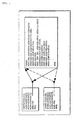
- FIG. 5 is a functional block diagram of an essential portion of a numerical control apparatus according to an embodiment of the present invention.
- program analyzing means 41 in a program analyzing section 4 of the numerical control apparatus are axis address correspondence means 41a for storing correspondences between axis addresses and controlled axis numbers set in a memory 1 by using parameters or the like, controlled axis number obtaining means 41b for obtaining controlled axis numbers from a command program 2, and variable/operation type analyzing means 41c for performing analysis based on variables'stored in the memory 3 and operational expressions designated by the command program 2.
- Axis addresses using axis names are given to an axis for moving a table or the like in a forward/backward direction, an axis for moving it in a left/right direction, an axis for moving it in a vertical direction, and the like when viewed from a front of amachine, and the axis address correspondence means 41a stores correspondences between the axis addresses and the controlled axis numbers of the respective axes.
- the correspondences between the axis addresses using the axis names given to the respective axes and the controlled axis numbers are set and stored by setting the parameters or the like.
- the variable/operation type analyzing means 41c performs the operation designated by the command program to obtain the controlled axis number and the like.
- the controlled axis number obtaining means 41b obtains the controlled axis number from the axis address designated by the command program 2 and a result obtained by the variable/operation type analyzing means 41c and outputs a movement amount (42 1 to 42 n ) corresponding to the controlled axis number.
- An interpolation control section 5 performs interpolating processing for each predetermined interpolation cycle and outputs a movement amount (61 1 to 61 n ) for each predetermined interpolation cycle to an axis control section of a designated controlled axis number.
- the axis control section 6 determines an axis to which the movement amount is actually output based on the controlled axis number by a controlled axis correspondence means 62 and drives a motor (8 1 to 8 n ) of each the axis through a servo amplifier (7 1 to 7 n ).
- the above-described numerical control apparatus is different in structure from a conventional numerical control apparatus in that the numerical control apparatus includes the controlled axis number obtaining means 41b and the variable/operation type analyzing means 41c as the program analyzing means 41, but is similar to a conventional numerical control apparatus in other respects.
- an indirect axis address designating method for designating the movement amount to the controlled axis by using the controlled axis number is used and it is possible to control the machine by designating the controlled axis number by the command program.
- commands for designating the controlled axes by using the controlled axis numbers are prepared in the present embodiment.
- the axis address correspondence means 41a brings an axis address X into correspondence with a controlled axis number 1, an axis address Y with a controlled axis number 2, and an axis address Z with a controlled axis number 3. Comparing the programs shown in FIG. 6 with the program shown in FIG. 2A, it is seen that "X", “Y” and “Z” in the program shown in FIG. 2A is replaced with "AX[1]”, “AX[2]” and "AX[3]", respectively, in the command program shown in FIG. 6.
- an axis address U is to be brought into correspondence with the controlled axis number 1, an axis address V with the controlled axis number 2, and an axis address W with the controlled axis number 3 by the axis address correspondence means 41a.
- the controlled axis numbers can be changed by using variables in the present invention.
- a command "AXNUM [axis address]" is provided.
- #100 AXNUM [X] is a command for assigning the controlled axis number of the axis address X to a variable #100.
- the two command programs as shown in FIGS. 4A and 4B has to be written as described above.
- FIG. 7 shows an example of the command program for giving commands to the three basic axes X, Y, and Z and the parallel axes U, V, and W as in FIGS. 4A and 4B but written by using this "AXNUM [axis address]" command.
- a controlled axis number of an axis address X is brought into correspondence with "1”
- a controlled axis number of an axis address U with "4" a controlled axis number of an axis address V with "5"
- a controlled axis number of an axis address W with "6".
- the command program "00090" becomes the same as the command program shown in FIG. 4A.
- a command program shown in FIG. 8 is a program for providing the same numeral to axis addresses X to C and carrying out cutting in turn.
- Such command program can be simplified by performing the operations by using the variables as shown in FIG. 9.
- controlled axis numbers 1, 2, 3, 4, 5, 6, 7, 8, and 9 are brought into correspondence with the axis addresses X, Y, Z, U, V, W, A, B, and C.
- the command program as shown in FIG. 8 has to be written to carry out the same operations in prior art, the program can be simplified in the present invention as shown in FIG. 9. Moreover, because the axes addresses are converted into numerals as the controlled axis numbers, the simple command program can be written by performing the various operations by using the numerals.
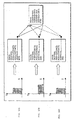
- FIG. 10A shows a rectangular shape in the X-Y plane and FIG. 10B shows a shape obtained by rotating the rectangle by 90° on the X-Y plane.
- FIG. 10C shows an example in which the same rectangular shape is applied to the Z-X plane.
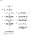
- FIG. 11 is a flowchart of an essential part of processing performed by a processor of the numerical control apparatus of the embodiment.
- one word is read from the command program (step 100) and whether it is an end-of-block character, ";" or not is judged (step 101). If it is the end-of-block character, a movement amount of each the controlled axis generated in one block is output (step 102).
- One block refers to a group of words surrounded by an end-of-block character and the next end-of-block character. After analyzing the command program by the block, the generated movement amount is output.
- step 103 determines whether the word is the end-of-block character. If it is an indirect axis address command or not is judged (step 103) . If it is not the indirect axis address command, the movement amount is obtained by prior-art processing (step 104) and the processor returns to step 100 to read the next word. From then on, if it is not the indirect axis address command, processing in steps 100 to 104 is repeatedly executed and an obtained movement amount is output when an end-of-block character is read in (step 102).
- step 105 whether a controlled axis number command is a variable or not is judged. If it is a variable, the controlled axis number is obtained from the variable (step 106) to generate a movement amount of the obtained controlled axis number (step 110) . Then, the processing returns to step 100 to read the next one word. If the word is an indirect axis address command and the controlled axis number is not the variable, whether the controlled axis number command is operation or not is judged at step 107. If it is an operation, the operation is performed (step 108), the controlled axis number is obtained from a result of the operation (step 109) , the movement amount of the obtained controlled axis number is generated (step 110) , and the processor returns to step 100.
- step 107 If the word is an indirect axis address command and the controlled axis number command is neither variable nor operation, i.e., if the indirect axis address command directly designates a controlled axis number, the processing proceeds from step 107 to step 110 to generate the movement amount of the controlled axis number.
- the axis address is designated to assign the controlled axis number to the variable in the above-described embodiment, it is also possible to directly store the controlled axis number in the variable.
- "#100 AXNUM[1]"
Landscapes
- Engineering & Computer Science (AREA)
- Human Computer Interaction (AREA)
- Manufacturing & Machinery (AREA)
- Physics & Mathematics (AREA)
- General Physics & Mathematics (AREA)
- Automation & Control Theory (AREA)
- Numerical Control (AREA)
Abstract
Description
"AX [controlled axis number] ="
is provided and the controlled axis is designated by this command. For example, to form a command for moving a controlled axis number "1" by 123.456 as a program command, the command is
AX [1] = 123.456;
#100 = AXNUM [X]
is a command for assigning the controlled axis number of the axis address X to a
AX [#100] = AX [4] = U,
AX [#101] = AX [5] = V, and
AX [#102] = AX [6] = W
in this command program and it becomes the command program for carrying out the same operation as the command program shown in FIG. 4B.
AX [#100] = AX [1] = 50.0
AX [#101] = AX [2] = 100.0
AX [#100] = AX [1] = -50.0
AX [#100] = AX [2] = -100.0
and, by executing this, after movement by "50.0" in a direction of the X axis, movement by "100.0" in a direction of the Y axis occurs and then movement by "-50.0" in the direction of the X axis and movement by "-100.0" in the direction of the Y axis occur to cause operation in the rectangular shape shown in a coordinate system in FIG. 10A.
AX [#100] = AX [2] = 50.0
AX [#101] = AX [1] = 100.0
AX [#100] = AX [2] = -50.0
AX [#100] = AX [1] = -100.0
and, by executing this, after movement by "50.0" in a direction of the Y axis, movement by "100.0" in a direction of the X axis occurs and then movement by "-50.0" in the direction of the Y axis and movement by "-100.0" in the direction of the X axis occur to cause operation in the rectangular shape shown in a coordinate system in FIG. 10B, i.e., to cause operation in the shape obtained by rotating the rectangular shape shown in FIG. 10A by 90°.
AX [#100] = AX [3] = 50.0
AX [#101] = AX [1] = 100.0
AX [#100] = AX [3] = -50.0
AX [#100] = AX [1] = -100.0
and, by executing this, after movement by "50.0" in a direction of the Z axis, movement by "100.0" in the direction of the X axis occurs and then movement by "-50.0" in the direction of the Z axis and movement by "-100.0" in the direction of the X axis occur to apply the same shape as the rectangular shape shown in FIG. 10A to the Z-X plane as shown in FIG. 10C.
Claims (4)
- A numerical control apparatus capable of controlling a plurality of controlled axes and comprising:wherein the plurality of axes are controlled according to the movement amounts or positional information analyzed by the program analyzing means.storage means for storing a command program describing movement amounts or positional information of controlled axes commanded in association with the axis numbers of the controlled axes; andprogram analyzing means for analyzing the command program to decode it into the movement amounts or positional information of the axes;
- The numerical control apparatus according to claim 1, further comprising variable storage means for storing controlled axis numbers to be designated and set by the command program, wherein the controlled axis numbers can be designatedby using variables.
- A numerical control apparatus capable of controlling a plurality of controlled axes, comprising:wherein the plurality of controlled axes are controlled based on the controlled axis numbers obtained from the controlled axis number obtaining means.storage means for storing correspondences between axis addresses designating the controlled axes and controlled axis numbers; andcontrolled axis number obtaining means for obtaining the controlled axis numbers from the axis addresses written in the command program, based on the correspondences stored in the storage means;
- The numerical control apparatus according to claim 1 or 3, wherein the controlled axis numbers are designated by using operational expressions.
Applications Claiming Priority (2)
| Application Number | Priority Date | Filing Date | Title |
|---|---|---|---|
| JP2002352552 | 2002-12-04 | ||
| JP2002352552A JP2004185397A (en) | 2002-12-04 | 2002-12-04 | Numerical control apparatus |
Publications (2)
| Publication Number | Publication Date |
|---|---|
| EP1431849A2 true EP1431849A2 (en) | 2004-06-23 |
| EP1431849A3 EP1431849A3 (en) | 2004-09-22 |
Family
ID=32376174
Family Applications (1)
| Application Number | Title | Priority Date | Filing Date |
|---|---|---|---|
| EP03257575A Withdrawn EP1431849A3 (en) | 2002-12-04 | 2003-12-02 | Numerical control apparatus |
Country Status (3)
| Country | Link |
|---|---|
| US (1) | US20040138777A1 (en) |
| EP (1) | EP1431849A3 (en) |
| JP (1) | JP2004185397A (en) |
Families Citing this family (1)
| Publication number | Priority date | Publication date | Assignee | Title |
|---|---|---|---|---|
| JP5845228B2 (en) * | 2013-10-23 | 2016-01-20 | ファナック株式会社 | Tool path curving device |
Family Cites Families (13)
| Publication number | Priority date | Publication date | Assignee | Title |
|---|---|---|---|---|
| JPS5890113A (en) * | 1981-11-25 | 1983-05-28 | Yamazaki Mazak Corp | Establishment control of coordinate system at machining center |
| JPS5981707A (en) * | 1982-10-30 | 1984-05-11 | Fanuc Ltd | Automatic producing method of nc data |
| US4918627A (en) * | 1986-08-04 | 1990-04-17 | Fmc Corporation | Computer integrated gaging system |
| EP0405302A3 (en) * | 1989-06-30 | 1993-03-03 | Siemens Aktiengesellschaft | Operation method of a numerically controlled machine |
| JP2762788B2 (en) * | 1991-08-30 | 1998-06-04 | 三菱電機株式会社 | Moving body operation display device and display method thereof |
| DE4321631B4 (en) * | 1993-06-30 | 2010-09-23 | Robert Bosch Gmbh | Method for generating NC control data |
| JP3407490B2 (en) * | 1994-08-31 | 2003-05-19 | 三菱電機株式会社 | Numerical control method and device |
| JPH09101814A (en) * | 1995-10-06 | 1997-04-15 | Fanuc Ltd | Numerical controller and automatic programming device |
| US5828574A (en) * | 1997-05-19 | 1998-10-27 | General Electric Company | Adaptive feedrates from geometry modeling for NC machining |
| JP3856531B2 (en) * | 1997-06-26 | 2006-12-13 | 山形カシオ株式会社 | Coordinate data conversion method and apparatus |
| DE19739559A1 (en) * | 1997-09-09 | 1999-03-18 | Traub Drehmaschinen Gmbh I L | Process and system for creating or visualizing control data records |
| DE19754460A1 (en) * | 1997-12-08 | 1999-06-10 | Siemens Ag | Numerical machine tool control device |
| JP4398044B2 (en) * | 2000-02-03 | 2010-01-13 | 東芝機械株式会社 | Numerical control device and control method for machine tool |
-
2002
- 2002-12-04 JP JP2002352552A patent/JP2004185397A/en active Pending
-
2003
- 2003-12-02 EP EP03257575A patent/EP1431849A3/en not_active Withdrawn
- 2003-12-03 US US10/725,936 patent/US20040138777A1/en not_active Abandoned
Also Published As
| Publication number | Publication date |
|---|---|
| US20040138777A1 (en) | 2004-07-15 |
| EP1431849A3 (en) | 2004-09-22 |
| JP2004185397A (en) | 2004-07-02 |
Similar Documents
| Publication | Publication Date | Title |
|---|---|---|
| KR100347297B1 (en) | Numerical Control Method | |
| EP1195665B1 (en) | Apparatus and method for setting control parameters of machining apparatus | |
| CN112508763B (en) | Laser processing method, laser processing apparatus, and storage medium | |
| CN103529753B (en) | Possesses the numerical control device that program restarts function | |
| JP2002189510A (en) | Processing related information generating device and numerical control device provided with the same | |
| EP0124615A1 (en) | Method of automatically preparing numerical control data | |
| KR100421789B1 (en) | Numerical Control Instruction Writing Device and Method | |
| US7058473B2 (en) | Method and device for generation of machining program | |
| US6909939B1 (en) | Numerical control method and numerical control device | |
| JP2009053823A (en) | Machining simulation device | |
| JP3207125B2 (en) | Turret tool selection command method | |
| US7139635B2 (en) | Multi-system numerical control device | |
| US20040138777A1 (en) | Numerical control apparatus | |
| US11194313B2 (en) | Numerical controller | |
| JP4343072B2 (en) | NC machining simulation equipment | |
| CN115562174A (en) | Machine tool follow-up cutting simulation method based on G codes | |
| KR100221564B1 (en) | Processing method and device to determine the optimum processing condition | |
| JPS59211105A (en) | Producing method of part program | |
| JP2002091526A (en) | Numerical controller | |
| JP2779796B2 (en) | Numerical control unit | |
| JPS6232503A (en) | Numerical controller | |
| JP2642451B2 (en) | Numerical control unit | |
| CN121635120A (en) | Multi-head CNC machine tool system and its control method supporting RTCP function | |
| JPH01228755A (en) | Plural groove machining method | |
| JP2704124B2 (en) | Wire electric discharge machining method and apparatus |
Legal Events
| Date | Code | Title | Description |
|---|---|---|---|
| PUAI | Public reference made under article 153(3) epc to a published international application that has entered the european phase |
Free format text: ORIGINAL CODE: 0009012 |
|
| AK | Designated contracting states |
Kind code of ref document: A2 Designated state(s): AT BE BG CH CY CZ DE DK EE ES FI FR GB GR HU IE IT LI LU MC NL PT RO SE SI SK TR |
|
| AX | Request for extension of the european patent |
Extension state: AL LT LV MK |
|
| PUAL | Search report despatched |
Free format text: ORIGINAL CODE: 0009013 |
|
| AK | Designated contracting states |
Kind code of ref document: A3 Designated state(s): AT BE BG CH CY CZ DE DK EE ES FI FR GB GR HU IE IT LI LU MC NL PT RO SE SI SK TR |
|
| AX | Request for extension of the european patent |
Extension state: AL LT LV MK |
|
| 17P | Request for examination filed |
Effective date: 20041201 |
|
| AKX | Designation fees paid |
Designated state(s): DE |
|
| STAA | Information on the status of an ep patent application or granted ep patent |
Free format text: STATUS: THE APPLICATION IS DEEMED TO BE WITHDRAWN |
|
| 18D | Application deemed to be withdrawn |
Effective date: 20061019 |