EP1431817A1 - Roll support member and recording material package employing same - Google Patents
Roll support member and recording material package employing same Download PDFInfo
- Publication number
- EP1431817A1 EP1431817A1 EP03028670A EP03028670A EP1431817A1 EP 1431817 A1 EP1431817 A1 EP 1431817A1 EP 03028670 A EP03028670 A EP 03028670A EP 03028670 A EP03028670 A EP 03028670A EP 1431817 A1 EP1431817 A1 EP 1431817A1
- Authority
- EP
- European Patent Office
- Prior art keywords
- support member
- roll support
- roll
- protruding portion
- cylindrical protruding
- Prior art date
- Legal status (The legal status is an assumption and is not a legal conclusion. Google has not performed a legal analysis and makes no representation as to the accuracy of the status listed.)
- Granted
Links
- 239000000463 material Substances 0.000 title claims abstract description 125
- 239000000758 substrate Substances 0.000 claims abstract description 65
- -1 polyethylene Polymers 0.000 claims description 15
- 230000002093 peripheral effect Effects 0.000 claims description 8
- 239000004698 Polyethylene Substances 0.000 claims description 7
- 239000004743 Polypropylene Substances 0.000 claims description 7
- 229920000573 polyethylene Polymers 0.000 claims description 7
- 229920001155 polypropylene Polymers 0.000 claims description 7
- 229920001400 block copolymer Polymers 0.000 claims description 6
- 239000005022 packaging material Substances 0.000 abstract description 17
- 238000004519 manufacturing process Methods 0.000 description 5
- 239000000123 paper Substances 0.000 description 5
- 230000000593 degrading effect Effects 0.000 description 4
- 238000001746 injection moulding Methods 0.000 description 4
- 229920003002 synthetic resin Polymers 0.000 description 3
- 239000000057 synthetic resin Substances 0.000 description 3
- 230000000717 retained effect Effects 0.000 description 2
- 235000011960 Brassica ruvo Nutrition 0.000 description 1
- 230000000052 comparative effect Effects 0.000 description 1
- 230000006835 compression Effects 0.000 description 1
- 238000007906 compression Methods 0.000 description 1
- 238000000034 method Methods 0.000 description 1
- 230000000149 penetrating effect Effects 0.000 description 1
- 229920001296 polysiloxane Polymers 0.000 description 1
- 230000003252 repetitive effect Effects 0.000 description 1
- 229920002050 silicone resin Polymers 0.000 description 1
- 229910052709 silver Inorganic materials 0.000 description 1
- 239000004332 silver Substances 0.000 description 1
- 229940100890 silver compound Drugs 0.000 description 1
- 150000003379 silver compounds Chemical class 0.000 description 1
- 239000000243 solution Substances 0.000 description 1
- 238000004804 winding Methods 0.000 description 1
Images



Classifications
-
- G—PHYSICS
- G03—PHOTOGRAPHY; CINEMATOGRAPHY; ANALOGOUS TECHNIQUES USING WAVES OTHER THAN OPTICAL WAVES; ELECTROGRAPHY; HOLOGRAPHY
- G03C—PHOTOSENSITIVE MATERIALS FOR PHOTOGRAPHIC PURPOSES; PHOTOGRAPHIC PROCESSES, e.g. CINE, X-RAY, COLOUR, STEREO-PHOTOGRAPHIC PROCESSES; AUXILIARY PROCESSES IN PHOTOGRAPHY
- G03C3/00—Packages of films for inserting into cameras, e.g. roll-films, film-packs; Wrapping materials for light-sensitive plates, films or papers, e.g. materials characterised by the use of special dyes, printing inks, adhesives
-
- B—PERFORMING OPERATIONS; TRANSPORTING
- B65—CONVEYING; PACKING; STORING; HANDLING THIN OR FILAMENTARY MATERIAL
- B65H—HANDLING THIN OR FILAMENTARY MATERIAL, e.g. SHEETS, WEBS, CABLES
- B65H75/00—Storing webs, tapes, or filamentary material, e.g. on reels
- B65H75/02—Cores, formers, supports, or holders for coiled, wound, or folded material, e.g. reels, spindles, bobbins, cop tubes, cans, mandrels or chucks
- B65H75/18—Constructional details
- B65H75/185—End caps, plugs or adapters
-
- B—PERFORMING OPERATIONS; TRANSPORTING
- B65—CONVEYING; PACKING; STORING; HANDLING THIN OR FILAMENTARY MATERIAL
- B65H—HANDLING THIN OR FILAMENTARY MATERIAL, e.g. SHEETS, WEBS, CABLES
- B65H2701/00—Handled material; Storage means
- B65H2701/50—Storage means for webs, tapes, or filamentary material
- B65H2701/51—Cores or reels characterised by the material
- B65H2701/512—Cores or reels characterised by the material moulded
- B65H2701/5122—Plastics
-
- B—PERFORMING OPERATIONS; TRANSPORTING
- B65—CONVEYING; PACKING; STORING; HANDLING THIN OR FILAMENTARY MATERIAL
- B65H—HANDLING THIN OR FILAMENTARY MATERIAL, e.g. SHEETS, WEBS, CABLES
- B65H2701/00—Handled material; Storage means
- B65H2701/50—Storage means for webs, tapes, or filamentary material
- B65H2701/53—Adaptations of cores or reels for special purposes
- B65H2701/534—Stackable or interlockable reels or parts of reels
Definitions
- the present invention relates to a pair of roll support members that are used when housing in a packaging material a roll-form recording material comprising a long length of recording material sheet wound around a cylindrical core, and a recording material package in which a roll-form recording material has opposite ends thereof supported by a pair of roll support members and is housed in a packaging material.
- the recording material sheet when storing and transporting a long length of recording material sheet, the recording material sheet is generally wound into roll form around a cylindrical core, then housed in a pulp-made packaging material such as a corrugated cardboard housing, and stored and transported.
- the outermost peripheral portion of such a roll-form recording material sheet (hereinafter called a roll-form recording material) is usually covered by a light-shielding sheet so that, when the recording material is a light-sensitive material, it is not exposed to light or damaged, and the opposite ends thereof in the width direction are also protected by light-shielding protecting plates so that it is not exposed to light or damaged from the opposite ends.
- a roll support member having a protruding portion formed integrally with a flat substrate (a flange having a protruding portion) has been proposed.
- the roll-form recording material is supported by the flat substrates when housing the roll-form recording material in the packaging material, and it is therefore possible to support the recording material so that it is not in contact with the packaging material.
- this roll support member is formed using a synthetic resin material as a main component, the flat substrate has the problem that its cushioning properties and mechanical strength are insufficient.
- the roll-form recording material when the roll-form recording material is stored for a long period of time, in a case in which the recording material is a light-sensitive material, a silver compound, etc. contained in the light-sensitive material reacts with moisture in air, thus degrading the light-sensitive material and causing uneven recording in some cases. Since the outer peripheral portion and the end portion of the light-sensitive material roll are covered by the light-shielding sheet and the protecting plate as described above, moisture in the air hardly penetrates it.
- a pulp material is widely employed as the core of the light-sensitive material roll, the pulp material being advantageous in terms of strength and cost but having poor moisture resistance, and the hollow portion thereof is usually in contact with the outside air.
- the light-sensitive material roll when the light-sensitive material roll is stored for a long period of time, not only is it necessary to protect the light-sensitive material roll from physical impact and prevent it from being deformed or damaged, but also it is necessary to prevent the hollow portion of the core from contacting the outside air and moisture penetrating.
- a roll support member has been proposed that is formed from a highly moisture-resistant synthetic resin, can be inserted (fitted) into a core, and is used in combination with a cushioning member formed from a low density material, that is, a recording material package (recording material) in which a roll-form recording material core and a roll support member therefor are united with a cushioning member therebetween and housed in a packaging material. Since the roll-form recording material core is thus blocked by the highly moisture-resistant roll support members inserted (fitted) thereinto, the hollow portion of the core is not in contact with the outside air. Moreover, even when the recording material package is exposed to a physical impact such as being dropped, since the cushioning member, which is formed from a low density material, alleviates the impact, the roll support member and the roll-form recording material are resistant to deformation and damage.
- the above-mentioned roll support member comprising the roll support member and the cushioning member has the problem that the cushioning member, which is a low density material, has poor resilience and is deformed by a physical impact such as being dropped.
- the cushioning member is deformed, thus degrading the cushioning properties.
- the recording material package receives an impact in this state, the impact is readily transmitted to the roll-form recording material, thus damaging or deforming the roll-form recording material. Because of this, in order to store and transport the roll-form recording material for a long period of time, it is necessary to make the cushioning member larger so that even when the cushioning member is deformed, the cushioning properties can be retained.
- the cushioning member makes the cushioning member larger requires a large packaging material for it to be housed in, it is disadvantageous in terms of resources and cost, and the space efficiency for its subsequent storage and the efficiency of transporting it are correspondingly degraded. Furthermore, since the roll support member and the cushioning member are molded using different materials, the number of production steps is large, the cost is high, and there are also disadvantages when it is recycled or disposed of after use.
- An object of the present invention is therefore to provide a roll support member that can support a roll-form recording material without damaging, deforming, or degrading the roll-form recording material even when it is housed in a packaging material and stored or transported for a long period of time, and that can reduce the production cost by making the thickness of the roll support member material thinner.
- Another object of the present invention is to provide a recording material package that enables efficient storage and transportation to be carried out.
- the other object of the present invention can be solved by the recording material package below.
- a roll support member having high resistance to drop impact can be obtained with low cost even when it is made of a thin, low strength material.
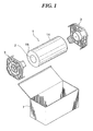
- FIG. 1 shows a schematic perspective view of each member when a roll-form recording material having the roll support member of the present invention mounted on each end thereof is housed in a case.
- a roll-form recording material 1 wound around a hollow cylindrical core 2 is wrapped with a light-shielding leader 14 and a light-shielding flange 15.
- Roll support members 3 are preferably made by injection molding.
- the roll-form recording material 1 is suspended and supported by the roll support members 3, and housed in a rectangular parallelepiped housing (case) 7.
- the roll-form recording material referred to in the present invention is a recording material in a state in which a long length of wide recording material is wound around a core in roll form.
- the long length of wide recording material referred to here is, for example, a recording material generally having a width of 152 mm, 610 mm, 864 mm, 1213 mm, etc. and a length of about 30 to 130 m. It is of course possible for the width and the length to be larger than the above.
- the roll-form recording material referred to in the present invention is not particularly limited and can include all types of image recording materials such as light-sensitive material used for photography, printing, photocopying, etc. and color copier image receiving paper.
- the light-sensitive material is not limited to a silver halide light-sensitive material (including a heat-developable light-sensitive material) and includes various types of light-sensitive material film, printing paper, etc.
- the roll support member 3 of the present invention comprises a rectangular substrate portion 4 having its mechanical strength improved by forming ribs on at least one side thereof, and preferably on both sides thereof, a cylindrical protruding portion 5 that is formed integrally with the substrate portion 4 at the center of one side of the substrate portion 4 and has the extremity thereof closed, and projecting portions 6 that are provided integrally with the substrate portion 4 so as to extend orthogonally from the four corners of the substrate portion 4.
- the substrate portion 4 has an outer peripheral portion between the outer periphery of a channel 8 and the outer edge of the substrate portion 4.
- Ribs 4a are provided on the outer peripheral portion of the substrate portion 4 on the side where the cylindrical protruding portion 5 is formed. In order to further improve the mechanical strength, it is desirable to provide ribs 4b on the opposite side.
- the ribs 4a and the ribs 4b are preferably provided in a radial manner.
- the dimensions of the substrate portion 4, that is, the distance W between two opposing sides of the square of the substrate portion 4, can be varied appropriately depending on the length of the recording material wound around the core 2, and are preferably 120 to 190 mm.
- the dimensions of the ribs 4a and the ribs 4b are preferably such that the height is in the range of 5 to 30 mm and the thickness is in the range of 1 to 2 mm, and the dimensions of each thereof may be identical to or different from each other.
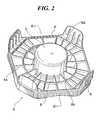
- the ribs are usually formed as shown, for example, in FIG. 2 and FIG. 3, in a radial manner with the cylindrical protruding portion 5 as the center that is formed at substantially the center of the substrate portion 4.
- the four corners of the substrate portion 4 are preferably cut off so that an impact will not be concentrated on the corners and break them.
- the rectangular shape of the substrate portion 4 is preferably a square. This is because, when the roll-form recording material supported by the roll support members is housed in a packaging material, it is possible to reduce wasted space and further reduce the dimensions of the packaging material.
- the outer diameter of the cylindrical protruding portion 5 is preferably smaller than the inner diameter of the core 2 of the roll-form recording material by an amount in the range of 0.1 to 3 mm.
- the difference between the outer diameter of the cylindrical protruding portion 5 and the inner diameter of the core 2 is in the above-mentioned range, since the cylindrical protruding portion 5 can easily be inserted into the core 2 and the hollow interior portion of the core 2 does not make contact with the outside air, it is resistant to moisture entrapment.
- the height of the cylindrical protruding portion 3 is preferably in the range of 10 to 40 mm, and more preferably in the range of 20 to 30 mm.
- the cylindrical protruding portion 5 When the height of the cylindrical protruding portion is in the above-mentioned range, since the cylindrical protruding portion 5 can easily be inserted into the core 2 and the hollow interior portion of the core 2 does not make contact with the outside air, it is resistant to moisture entrapment.
- the projecting portions 6 are preferably provided in the same direction as that of cylindrical protruding portion 5, which has its extremity closed. Moreover, it is preferable for all of the projecting portions 6 to have an identical height and for it to be the same as or higher than that of the cylindrical protruding portion 5. Adjusting the height of the projecting portions in this way enables the roll-form recording material to be supported in a stable manner.
- the cylindrical protruding portion 5 forms a hollow interior portion and has within the hollow interior portion a concentric cylindrical rib 5a disposed in a cylindrical shape that is substantially concentric (coaxial) with the cylindrical protruding portion, and radial ribs 5b that are disposed so as to provide a connection between the concentric cylindrical rib 5a and the surface on the hollow interior portion side of the cylindrical protruding portion 5.
- the cylindrical protruding portion 5 of the present invention preferably has a thickness S of 0.5 to 3 mm.
- the channel 8 which is U-shaped, is provided on the side of the rectangular substrate portion 4 on which the cylindrical protruding portion 5 is formed in a section where the cylindrical protruding portion 5 and the rectangular substrate portion 4 intersect, so as to surround the base of the cylindrical protruding portion 5.
- the channel 8 has in the interior thereof ribs 8a disposed in a radial manner with the cylindrical protruding portion 5 as the center.
- the reverse surface 8b of the bottom of the channel 8 (the side where there is no cylindrical protruding portion and there are no projecting portions) preferably has no ribs and is smooth.
- the depth of the channel is preferably such that the reverse surface of the bottom of the channel is level with the height of the ribs 4b.
- the roll-form recording material 1 can be held by the depressions, and it can therefore be used as a roll-form recording material holder.
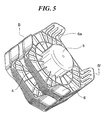
- FIG. 5 shows a schematic perspective view of the roll support members of the embodiment of the present invention when stacked.
- FIG. 6 is a schematic cross-sectional view along line B-B' of FIG. 5.
- the projecting portions 6 are preferably provided so as to extend outward relative to the outer periphery of the four corner-cut rectangular substrate portion 4.
- ribs 6a are preferably provided on the inside of the projecting portions 6. Providing the ribs 6a enables the strength of the projecting portions 6 to be increased.
- the rectangular substrate portion 4 is contained within the four projecting portions 6 and, furthermore, the rectangular substrate portion 4 can be retained by the ribs 6a, thus making the stacking properties excellent.
- the height H of the ribs 6a is preferably 15 to 25 mm from the viewpoint of supporting the substrate portion 4.
- FIG. 7 and FIG. 8 show a schematic perspective view when the roll support members of the present invention are stacked.
- the projecting portion 6 of the roll support member has step portions 6b provided at the extremity thereof. These step portions 6b retain the rectangular substrate portion 4, thus enabling the roll support members to be stored in a stacked state.
- the substrate portion 4 of the roll support member has notches 4c provided therein. By superimposing the notches 4c on the projecting portions 6, the roll support members can be stored in a stacked state.
- the roll support member of the present invention comprises a block copolymer of polyethylene and polypropylene as a main component material.
- the mixing ratio of the polyethylene relative to the polypropylene is preferably in the range of 2 to 15 wt %.
- Examples of such a block copolymer of polyethylene and polypropylene include BC1B, BC2E, BC3M, BC4, BC4ASW, BC5C, BC6, and BC8 (manufactured by Japan Polychem Corp.) and J-466HP (manufactured by Idemitsu Petrochemical).
- the roll support member of the present invention is preferably formed by injection molding.
- a silicone resin e.g., Silicone MCP manufactured by Hexa Chemical Co., Ltd.
- a silicone resin e.g., Silicone MCP manufactured by Hexa Chemical Co., Ltd.
- a paper material used for the rectangular parallelepiped case 7 is not particularly limited, but corrugated cardboard is preferable from the viewpoint of handling, ease of production, and strength.
- corrugated cardboard general A flute to E flute double-faced corrugated cardboard, and double-walled corrugated cardboard such as those described in 'Saishin Kami Kako Binran (Current Paper Processing Handbook)' Ed. by The Paper Processing Handbook Committee (K.K. Tech Times, 1988) are preferably used, but there are no particular restrictions. It is selected appropriately according to the dimensions of the roll-form recording material.
- a light-shielding moisture-resistant material of a light-shielding sheet, a light-shielding protection plate, etc. is not particularly limited as long as it does not affect the photographic performance and it has light-shielding and moisture-resistant performance and, for example, light-shielding moisture-resistant materials described in JP-A-6-95302 and JP-A-8-179473 can be used.
- the recording material package of the present invention is formed by inserting the cylindrical protruding portion 5 of the roll support member 3 of the present invention into each of opposite ends of the core 2 of the roll-form recording material 1, and housing it in the rectangular parallelepiped housing (case) 7 such as a corrugated cardboard housing.
- the roll-form recording material of the present invention in particular a roll-form light-sensitive material, is produced by winding a long length of recording material sheet around the cylindrical core 2 having a light-shielding flange 15 with light-shielding properties at opposite ends for protection so that the light-sensitive material will not be exposed to light and the light-sensitive material will not be scratched by contact with the roll support members.
- the outer periphery of the roll-form recording material 1 is protected by the light-shielding leader 14 so that the recording material will not be recorded on during storage. Furthermore, the roll-form recording material 1 is preferably protected by a moisture-resistant sheet, etc. so that the recording material will not be degraded by moisture in the air.
- the roll-form recording material housed in the packaging material in this way is supported by the roll support members so that the recording material sheet protected by the light-shielding leader will not come into contact with the packaging material.
- the mechanical strength is high and physical impacts can be absorbed, thereby preventing any damage or deformation.
- the roll support member 3 of the present invention enables the roll-form recording material 1 to be stored and transported in a packaging material for a long period of time without damaging or deforming the roll-form recording material and enables the recording material to be supported without degrading it.
- the cylindrical protruding portion 5 can be made of a thin material and, moreover, since the substrate portion 4, the cylindrical protruding portion 5, and the projecting portion 6 are formed integrally, the roll support member 3 of the present invention enables the production time to be shortened by 25% and the total weight of the roll support member 3 to be reduced by 30% compared with a conventional arrangement.
- the recording material package employing the roll support member 3 of the present invention can therefore be made with low cost and stored and transported efficiently.
- Roll support members were produced as shown in Table 1 by injection molding of a block copolymer of polyethylene and polypropylene (PE-PP).
- the substrate portion had ribs on both sides, the outer diameter of the cylindrical protruding portion was smaller by 1 mm than the inner diameter of the core of the light-sensitive material roll, and the height of the cylindrical protruding portion was 30 mm.
- the substrate portion of the roll support member thus obtained was compressed by a compression tester, and the amount of deformation of a part thus compressed was obtained.
- the amount of deformation in Table 1 is the ratio of the amount of deformation of each sample relative to the amount of deformation of a Reference Example sample. Thickness of substrate portion and cylindrical protruding portion (mm) Shape of substrate portion Ribs in hollow interior portion of cylindrical protruding portion Ribbed channel along cylindrical protruding portion Amount of deformation Comp.
- Ex. 2 1.0
- Ex. 3 1.0 Four corner-cut rectangular Present Absent 1.3
- Example 1 1.0 Four corner-cut rectangular Present Present 1.1 Reference Example 2.0 to 2.5 Rectangular Absent Absent 1.0
- the recording material package of Example 1 gave the same amount of deformation as that of Reference Example in which the thickness was 2.0 to 2.5 mm.
- a recording material package was made by inserting the cylindrical protruding portion of the above-mentioned roll support member into each of opposite ends of the core of a recording material roll and housing it in a pulp-made packaging material.
- This package was subjected to a drop test in accordance with JIS Z 0202, and the resistance of the roll support member to the drop impact was examined.
- the recording material package of Example 1 exhibited higher resistance to the drop impact than did the recording material packages of Comparative Examples 1 to 3, and had the same strength as that of Reference Example in which the thickness was 2.0 to 2.5 mm.
Landscapes
- Engineering & Computer Science (AREA)
- Microelectronics & Electronic Packaging (AREA)
- Physics & Mathematics (AREA)
- General Physics & Mathematics (AREA)
- Packaging Of Machine Parts And Wound Products (AREA)
- Packages (AREA)
- Unwinding Webs (AREA)
- Discharging, Photosensitive Material Shape In Electrophotography (AREA)
- Registering, Tensioning, Guiding Webs, And Rollers Therefor (AREA)
Abstract
Description
- The present invention relates to a pair of roll support members that are used when housing in a packaging material a roll-form recording material comprising a long length of recording material sheet wound around a cylindrical core, and a recording material package in which a roll-form recording material has opposite ends thereof supported by a pair of roll support members and is housed in a packaging material.
- Conventionally, when storing and transporting a long length of recording material sheet, the recording material sheet is generally wound into roll form around a cylindrical core, then housed in a pulp-made packaging material such as a corrugated cardboard housing, and stored and transported. The outermost peripheral portion of such a roll-form recording material sheet (hereinafter called a roll-form recording material) is usually covered by a light-shielding sheet so that, when the recording material is a light-sensitive material, it is not exposed to light or damaged, and the opposite ends thereof in the width direction are also protected by light-shielding protecting plates so that it is not exposed to light or damaged from the opposite ends. Furthermore, when such a light-sensitive material roll is housed in a packaging material, it is necessary to protect the light-sensitive material roll so that it will not be deformed or damaged by a physical impact such as being dropped and the light-sensitive material will not be recorded on due to the light-shielding sheet or protecting plate being damaged.
- With regard to a method for protecting a roll-form recording material and housing it in a packaging material, for example, a roll support member having a protruding portion formed integrally with a flat substrate (a flange having a protruding portion) has been proposed. By inserting the protruding portion of each of a pair of the roll support members into one of opposite ends of a core of the roll-form recording material, the roll-form recording material is supported by the flat substrates when housing the roll-form recording material in the packaging material, and it is therefore possible to support the recording material so that it is not in contact with the packaging material. However, when this roll support member is formed using a synthetic resin material as a main component, the flat substrate has the problem that its cushioning properties and mechanical strength are insufficient. That is, when a recording material package employing such a roll support member is exposed to a physical impact such as being dropped, the impact is transmitted directly to the roll-form recording material, thus deforming or damaging the roll-form recording material, or breaking the flat substrate thereby making it impossible to support the roll-form recording material in some cases. On the other hand, when the roll support member is formed using as a main component material a highly cushioning synthetic resin foamed material, even when the recording material package receives a physical impact such as being dropped, since the impact is absorbed by the flat substrate and is not transmitted to the roll-form recording material, the roll-form recording material will not be deformed or damaged. However, in this case, since a standard roll-form recording material is heavy (e.g., 4 kg or more), the protruding portions cannot bear the weight reliably and are damaged, thus easily becoming unable to support the roll-form recording material, which is a problem.
- On the other hand, when the roll-form recording material is stored for a long period of time, in a case in which the recording material is a light-sensitive material, a silver compound, etc. contained in the light-sensitive material reacts with moisture in air, thus degrading the light-sensitive material and causing uneven recording in some cases. Since the outer peripheral portion and the end portion of the light-sensitive material roll are covered by the light-shielding sheet and the protecting plate as described above, moisture in the air hardly penetrates it. On the other hand, a pulp material is widely employed as the core of the light-sensitive material roll, the pulp material being advantageous in terms of strength and cost but having poor moisture resistance, and the hollow portion thereof is usually in contact with the outside air. Therefore, when the light-sensitive material roll is stored for a long period of time, not only is it necessary to protect the light-sensitive material roll from physical impact and prevent it from being deformed or damaged, but also it is necessary to prevent the hollow portion of the core from contacting the outside air and moisture penetrating.
- A roll support member has been proposed that is formed from a highly moisture-resistant synthetic resin, can be inserted (fitted) into a core, and is used in combination with a cushioning member formed from a low density material, that is, a recording material package (recording material) in which a roll-form recording material core and a roll support member therefor are united with a cushioning member therebetween and housed in a packaging material. Since the roll-form recording material core is thus blocked by the highly moisture-resistant roll support members inserted (fitted) thereinto, the hollow portion of the core is not in contact with the outside air. Moreover, even when the recording material package is exposed to a physical impact such as being dropped, since the cushioning member, which is formed from a low density material, alleviates the impact, the roll support member and the roll-form recording material are resistant to deformation and damage.
- However, even the above-mentioned roll support member comprising the roll support member and the cushioning member has the problem that the cushioning member, which is a low density material, has poor resilience and is deformed by a physical impact such as being dropped. In particular, when the impact is large or repetitive, the cushioning member is deformed, thus degrading the cushioning properties. When the recording material package receives an impact in this state, the impact is readily transmitted to the roll-form recording material, thus damaging or deforming the roll-form recording material. Because of this, in order to store and transport the roll-form recording material for a long period of time, it is necessary to make the cushioning member larger so that even when the cushioning member is deformed, the cushioning properties can be retained. However, making the cushioning member larger requires a large packaging material for it to be housed in, it is disadvantageous in terms of resources and cost, and the space efficiency for its subsequent storage and the efficiency of transporting it are correspondingly degraded. Furthermore, since the roll support member and the cushioning member are molded using different materials, the number of production steps is large, the cost is high, and there are also disadvantages when it is recycled or disposed of after use.
- As a solution to these problems, a roll support member in which a flange portion and a cylindrical shaft for supporting a roll-form recording material are integrally formed has been disclosed (ref. JP-A-11-327089, JP-A-7-330032, and JP-A-2002-244249 (JP-A denotes a Japanese unexamined patent application publication)). However, this has the problem that in order to maintain sufficient strength against the impact of being dropped, the thickness of the roll support member must be increased, and there has been a desire for further improvement.
- An object of the present invention is therefore to provide a roll support member that can support a roll-form recording material without damaging, deforming, or degrading the roll-form recording material even when it is housed in a packaging material and stored or transported for a long period of time, and that can reduce the production cost by making the thickness of the roll support member material thinner. Another object of the present invention is to provide a recording material package that enables efficient storage and transportation to be carried out.
- One of the objects of the present invention can be attained by the roll support member below.
- (1) A roll support member comprising a four corner-cut rectangular substrate portion, a cylindrical protruding portion that is formed integrally with the substrate portion in the center of the surface on one side of the substrate portion and has the extremity thereof closed, and projecting portions that are formed integrally with the substrate portion so as to extend from each of four corners of the substrate portion in the direction in which the cylindrical protruding portion is formed, wherein the substrate portion has ribs formed on the surfaces of both sides thereof, the cylindrical protruding portion has a hollow interior portion formed therein, the hollow interior portion has a rib disposed in a cylindrical shape that is substantially concentric with the cylindrical protruding portion, and a radial rib disposed so as to provide a connection between the concentric cylindrical rib and the surface on the hollow interior portion side of the cylindrical protruding portion, the side of the substrate portion on which the cylindrical protruding portion is formed is provided with a U-shaped channel in a section where the cylindrical protruding portion and the substrate portion intersect, the channel surrounding the base of the cylindrical protruding portion, and the channel has a rib therewithin, the rib being disposed in a radial manner with the cylindrical protruding portion as the center.
-
- Preferred embodiments of the roll support member are listed below.
- (2) The roll support member according to (1), wherein the projecting portions are provided so as to extend outward relative to the outer periphery of the substrate portion, and the projecting portions have a rib on the inner side thereof.
- (3) The roll support member according to either (1) or (2), wherein the reverse surface of the bottom of the channel has no rib.
- (4) The roll support member according to any one of (1) to (3), wherein the substrate portion has an outer peripheral portion between the outer periphery of the channel and the outer edge of the substrate portion, and the outer peripheral portion has on both sides a plurality of radially disposed ribs.
- (5) The roll support member according to any one of (1) to (4), wherein the rectangular shape is a square having sides of 120 to 190 mm, and the cylindrical protruding portion has a height of 10 to 40 mm.
- (6) The roll support member according to any one of (1) to (5), wherein the projecting portions have an identical height and are no shorter than the height of the cylindrical protruding portion.
- (7) The roll support member according to any one of (1) to (6), wherein the side of the substrate portion opposite to the side where the cylindrical protruding portion is formed is provided with a depression for holding a roll-form recording material.
- (8) The roll support member according to any one of (1) to (7), wherein in order to stack at least two roll support members, the projecting portion has a step provided at the extremity thereof, or the substrate portion has a notch provided therein.
- (9) The roll support member according to any one of (1) to (8), wherein the roll support member is made of a block copolymer of polyethylene and polypropylene.
-
- The other object of the present invention can be solved by the recording material package below.
- (10) A recording material package in which a roll-form recording material is suspended and supported by the roll support member according to any one of (1) to (9) and housed in a rectangular parallelepiped housing.
-
- In accordance with the present invention, a roll support member having high resistance to drop impact can be obtained with low cost even when it is made of a thin, low strength material.
- FIG. 1 is a schematic perspective view of each member when a roll-form recording material having a roll support member of one embodiment of the present invention mounted on each end thereof is housed in a case.
- FIG. 2 is a schematic perspective view of the side of the roll support member of the embodiment of the present invention from which the cylindrical protruding portion projects.
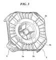
- FIG. 3 is a schematic perspective view of the side of the roll support member of the embodiment of the present invention opposite to that from which the cylindrical protruding portion projects.
- FIG. 4 is a schematic cross sectional perspective view along line A-A' of FIG. 2.
- FIG. 5 is a schematic perspective view of roll support members of the embodiment of the present invention when stacked.
- FIG. 6 is a schematic cross sectional view along line B-B' of FIG. 5.
- FIG. 7 is a schematic perspective view of roll support members of one embodiment of the present invention when stacked.
- FIG. 8 is a schematic perspective view of roll support members of one embodiment of the present invention when stacked.
-
- Modes for carrying out the present invention are explained below with reference to FIGS. 1 to 8, but the present invention is not limited thereto.
- FIG. 1 shows a schematic perspective view of each member when a roll-form recording material having the roll support member of the present invention mounted on each end thereof is housed in a case. In FIG. 1, a roll-
form recording material 1 wound around a hollowcylindrical core 2 is wrapped with a light-shielding leader 14 and a light-shielding flange 15.Roll support members 3 are preferably made by injection molding. The roll-form recording material 1 is suspended and supported by theroll support members 3, and housed in a rectangular parallelepiped housing (case) 7. - The roll-form recording material referred to in the present invention is a recording material in a state in which a long length of wide recording material is wound around a core in roll form. The long length of wide recording material referred to here is, for example, a recording material generally having a width of 152 mm, 610 mm, 864 mm, 1213 mm, etc. and a length of about 30 to 130 m. It is of course possible for the width and the length to be larger than the above. The roll-form recording material referred to in the present invention is not particularly limited and can include all types of image recording materials such as light-sensitive material used for photography, printing, photocopying, etc. and color copier image receiving paper. The light-sensitive material is not limited to a silver halide light-sensitive material (including a heat-developable light-sensitive material) and includes various types of light-sensitive material film, printing paper, etc.
- Perspective views of one example of the roll support member of the present invention are shown in FIG. 2 and FIG. 3, and a cross-sectional view thereof is shown in FIG. 4. The roll support member of the present invention is explained below with reference to FIGS. 2 to 4. The
roll support member 3 of the present invention comprises arectangular substrate portion 4 having its mechanical strength improved by forming ribs on at least one side thereof, and preferably on both sides thereof, acylindrical protruding portion 5 that is formed integrally with thesubstrate portion 4 at the center of one side of thesubstrate portion 4 and has the extremity thereof closed, and projectingportions 6 that are provided integrally with thesubstrate portion 4 so as to extend orthogonally from the four corners of thesubstrate portion 4. Thesubstrate portion 4 has an outer peripheral portion between the outer periphery of achannel 8 and the outer edge of thesubstrate portion 4.Ribs 4a are provided on the outer peripheral portion of thesubstrate portion 4 on the side where thecylindrical protruding portion 5 is formed. In order to further improve the mechanical strength, it is desirable to provideribs 4b on the opposite side. Theribs 4a and theribs 4b are preferably provided in a radial manner. - The dimensions of the
substrate portion 4, that is, the distance W between two opposing sides of the square of thesubstrate portion 4, can be varied appropriately depending on the length of the recording material wound around thecore 2, and are preferably 120 to 190 mm. - The dimensions of the
ribs 4a and theribs 4b are preferably such that the height is in the range of 5 to 30 mm and the thickness is in the range of 1 to 2 mm, and the dimensions of each thereof may be identical to or different from each other. The ribs are usually formed as shown, for example, in FIG. 2 and FIG. 3, in a radial manner with the cylindrical protrudingportion 5 as the center that is formed at substantially the center of thesubstrate portion 4. Furthermore, the four corners of thesubstrate portion 4 are preferably cut off so that an impact will not be concentrated on the corners and break them. Moreover, the rectangular shape of thesubstrate portion 4 is preferably a square. This is because, when the roll-form recording material supported by the roll support members is housed in a packaging material, it is possible to reduce wasted space and further reduce the dimensions of the packaging material. - The outer diameter of the cylindrical protruding
portion 5 is preferably smaller than the inner diameter of thecore 2 of the roll-form recording material by an amount in the range of 0.1 to 3 mm. When the difference between the outer diameter of the cylindrical protrudingportion 5 and the inner diameter of thecore 2 is in the above-mentioned range, since the cylindrical protrudingportion 5 can easily be inserted into thecore 2 and the hollow interior portion of thecore 2 does not make contact with the outside air, it is resistant to moisture entrapment. Furthermore, the height of the cylindrical protrudingportion 3 is preferably in the range of 10 to 40 mm, and more preferably in the range of 20 to 30 mm. When the height of the cylindrical protruding portion is in the above-mentioned range, since the cylindrical protrudingportion 5 can easily be inserted into thecore 2 and the hollow interior portion of thecore 2 does not make contact with the outside air, it is resistant to moisture entrapment. - The projecting
portions 6 are preferably provided in the same direction as that of cylindrical protrudingportion 5, which has its extremity closed. Moreover, it is preferable for all of the projectingportions 6 to have an identical height and for it to be the same as or higher than that of the cylindrical protrudingportion 5. Adjusting the height of the projecting portions in this way enables the roll-form recording material to be supported in a stable manner. - As shown in FIG. 3, in the
roll support member 3 of the present invention, the cylindrical protrudingportion 5 forms a hollow interior portion and has within the hollow interior portion a concentriccylindrical rib 5a disposed in a cylindrical shape that is substantially concentric (coaxial) with the cylindrical protruding portion, andradial ribs 5b that are disposed so as to provide a connection between the concentriccylindrical rib 5a and the surface on the hollow interior portion side of the cylindrical protrudingportion 5. By providing the ribs within the cylindrical protrudingportion 5 the cylindrical protrudingportion 5 of theroll support member 3 can be prevented from being damaged when the recording material package is dropped, etc. Conventionally, in order to maintain the strength of the cylindrical protrudingportion 5, it has been necessary to make the cylindrical protrudingportion 5 thick, but since the strength of theroll support member 3 of the present invention can be maintained by the ribs within the cylindrical protrudingportion 5, it is unnecessary to make the cylindrical protrudingportion 5 thick. The cylindrical protrudingportion 5 of the present invention preferably has a thickness S of 0.5 to 3 mm. - As shown in FIG. 2 and FIG. 3, in the
roll support member 3 of the present invention, thechannel 8, which is U-shaped, is provided on the side of therectangular substrate portion 4 on which the cylindrical protrudingportion 5 is formed in a section where the cylindrical protrudingportion 5 and therectangular substrate portion 4 intersect, so as to surround the base of the cylindrical protrudingportion 5. Thechannel 8 has in theinterior thereof ribs 8a disposed in a radial manner with the cylindrical protrudingportion 5 as the center. Thereverse surface 8b of the bottom of the channel 8 (the side where there is no cylindrical protruding portion and there are no projecting portions) preferably has no ribs and is smooth. The depth of the channel is preferably such that the reverse surface of the bottom of the channel is level with the height of theribs 4b. - As shown in FIG. 4, it is preferable to provide depressions on the side of the
substrate portion 4 that is opposite to the side where the cylindrical protrudingportion 5 is provided. By placing the roll-form recording material 1 on the reverse surface of thesubstrate portion 4 with the cylindrical protrudingportion 5 facing downward, the roll-form recording material 1 can be held by the depressions, and it can therefore be used as a roll-form recording material holder. - FIG. 5 shows a schematic perspective view of the roll support members of the embodiment of the present invention when stacked. FIG. 6 is a schematic cross-sectional view along line B-B' of FIG. 5.
- As shown in FIG. 5, the projecting
portions 6 are preferably provided so as to extend outward relative to the outer periphery of the four corner-cutrectangular substrate portion 4. Furthermore,ribs 6a are preferably provided on the inside of the projectingportions 6. Providing theribs 6a enables the strength of the projectingportions 6 to be increased. In addition, as shown in FIG. 5 and FIG. 6, when the roll support members are stacked for storage, therectangular substrate portion 4 is contained within the four projectingportions 6 and, furthermore, therectangular substrate portion 4 can be retained by theribs 6a, thus making the stacking properties excellent. The height H of theribs 6a is preferably 15 to 25 mm from the viewpoint of supporting thesubstrate portion 4. - As other embodiments, FIG. 7 and FIG. 8 show a schematic perspective view when the roll support members of the present invention are stacked. In FIG. 7, the projecting
portion 6 of the roll support member hasstep portions 6b provided at the extremity thereof. Thesestep portions 6b retain therectangular substrate portion 4, thus enabling the roll support members to be stored in a stacked state. In FIG. 8, thesubstrate portion 4 of the roll support member hasnotches 4c provided therein. By superimposing thenotches 4c on the projectingportions 6, the roll support members can be stored in a stacked state. - The roll support member of the present invention comprises a block copolymer of polyethylene and polypropylene as a main component material. The mixing ratio of the polyethylene relative to the polypropylene is preferably in the range of 2 to 15 wt %. Examples of such a block copolymer of polyethylene and polypropylene include BC1B, BC2E, BC3M, BC4, BC4ASW, BC5C, BC6, and BC8 (manufactured by Japan Polychem Corp.) and J-466HP (manufactured by Idemitsu Petrochemical). The roll support member of the present invention is preferably formed by injection molding. In order to improve the moldability during injection molding and reduce the friction of the contact surfaces of the roll support member and the light-sensitive material roll, it is preferable to add a silicone resin (e.g., Silicone MCP manufactured by Hexa Chemical Co., Ltd.) to the block copolymer of polyethylene and polypropylene in the range of 0.3 to 3 wt %.
- A paper material used for the
rectangular parallelepiped case 7 is not particularly limited, but corrugated cardboard is preferable from the viewpoint of handling, ease of production, and strength. With regard to the corrugated cardboard, general A flute to E flute double-faced corrugated cardboard, and double-walled corrugated cardboard such as those described in 'Saishin Kami Kako Binran (Current Paper Processing Handbook)' Ed. by The Paper Processing Handbook Committee (K.K. Tech Times, 1988) are preferably used, but there are no particular restrictions. It is selected appropriately according to the dimensions of the roll-form recording material. - A light-shielding moisture-resistant material of a light-shielding sheet, a light-shielding protection plate, etc. is not particularly limited as long as it does not affect the photographic performance and it has light-shielding and moisture-resistant performance and, for example, light-shielding moisture-resistant materials described in JP-A-6-95302 and JP-A-8-179473 can be used.
- That is, as shown in FIG. 1, the recording material package of the present invention is formed by inserting the cylindrical protruding
portion 5 of theroll support member 3 of the present invention into each of opposite ends of thecore 2 of the roll-form recording material 1, and housing it in the rectangular parallelepiped housing (case) 7 such as a corrugated cardboard housing. The roll-form recording material of the present invention, in particular a roll-form light-sensitive material, is produced by winding a long length of recording material sheet around thecylindrical core 2 having a light-shieldingflange 15 with light-shielding properties at opposite ends for protection so that the light-sensitive material will not be exposed to light and the light-sensitive material will not be scratched by contact with the roll support members. The outer periphery of the roll-form recording material 1 is protected by the light-shieldingleader 14 so that the recording material will not be recorded on during storage. Furthermore, the roll-form recording material 1 is preferably protected by a moisture-resistant sheet, etc. so that the recording material will not be degraded by moisture in the air. - The roll-form recording material housed in the packaging material in this way is supported by the roll support members so that the recording material sheet protected by the light-shielding leader will not come into contact with the packaging material.
- As hereinbefore described, in the
roll support member 3 of the present invention, since thesubstrate portion 4 of the support member has theribs portion 5 also has theribs 5a, the mechanical strength is high and physical impacts can be absorbed, thereby preventing any damage or deformation. Theroll support member 3 of the present invention enables the roll-form recording material 1 to be stored and transported in a packaging material for a long period of time without damaging or deforming the roll-form recording material and enables the recording material to be supported without degrading it. Furthermore, the cylindrical protrudingportion 5 can be made of a thin material and, moreover, since thesubstrate portion 4, the cylindrical protrudingportion 5, and the projectingportion 6 are formed integrally, theroll support member 3 of the present invention enables the production time to be shortened by 25% and the total weight of theroll support member 3 to be reduced by 30% compared with a conventional arrangement. The recording material package employing theroll support member 3 of the present invention can therefore be made with low cost and stored and transported efficiently. - Examples are explained below, but the present invention is not limited to these examples.
- Roll support members were produced as shown in Table 1 by injection molding of a block copolymer of polyethylene and polypropylene (PE-PP). In the roll support members thus obtained, the substrate portion had ribs on both sides, the outer diameter of the cylindrical protruding portion was smaller by 1 mm than the inner diameter of the core of the light-sensitive material roll, and the height of the cylindrical protruding portion was 30 mm.
- The substrate portion of the roll support member thus obtained was compressed by a compression tester, and the amount of deformation of a part thus compressed was obtained. The amount of deformation in Table 1 is the ratio of the amount of deformation of each sample relative to the amount of deformation of a Reference Example sample.
Thickness of substrate portion and cylindrical protruding portion
(mm)Shape of substrate portion Ribs in hollow interior portion of cylindrical protruding portion Ribbed channel along cylindrical protruding portion Amount of deformation Comp. Ex. 1 1.0 Rectangular Absent Absent 2.2 Comp. Ex. 2 1.0 Four corner-cut rectangular Absent Present 1.8 Comp. Ex. 3 1.0 Four corner-cut rectangular Present Absent 1.3 Example 1 1.0 Four corner-cut rectangular Present Present 1.1 Reference Example 2.0 to 2.5 Rectangular Absent Absent 1.0 - The recording material package of Example 1 gave the same amount of deformation as that of Reference Example in which the thickness was 2.0 to 2.5 mm.
- Furthermore, a recording material package was made by inserting the cylindrical protruding portion of the above-mentioned roll support member into each of opposite ends of the core of a recording material roll and housing it in a pulp-made packaging material. This package was subjected to a drop test in accordance with JIS Z 0202, and the resistance of the roll support member to the drop impact was examined. The recording material package of Example 1 exhibited higher resistance to the drop impact than did the recording material packages of Comparative Examples 1 to 3, and had the same strength as that of Reference Example in which the thickness was 2.0 to 2.5 mm.
Claims (10)
- A roll support member comprising:a four corner-cut rectangular substrate portion (4);a cylindrical protruding portion (5) that is formed integrally with the substrate portion (4) in the center of the surface on one side of the substrate portion (4) and has the extremity thereof closed; andprojecting portions (6) that are formed integrally with the substrate portion (4) so as to extend from each of four corners of the substrate portion (4) in the direction in which the cylindrical protruding portion (5) is formed; whereinthe substrate portion (4) has ribs (4a, 4b) formed on the surfaces of both sides thereof;the cylindrical protruding portion (5) has a hollow interior portion formed therein;the hollow interior portion has a rib (5a) disposed in a cylindrical shape that is substantially concentric with the cylindrical protruding portion (5), and a radial rib (5b) disposed so as to provide a connection between the concentric cylindrical rib (5a) and the surface on the hollow interior portion side of the cylindrical protruding portion (5);the side of the substrate portion (4) on which the cylindrical protruding portion (5) is formed is provided with a U-shaped channel (8) in a section where the cylindrical protruding portion (5) and the substrate portion (4) intersect, the channel (8) surrounding the base of the cylindrical protruding portion (5); andthe channel (8) has a rib (8a) therewithin, the rib (8a) being disposed in a radial manner with the cylindrical protruding portion (5) as the center.
- The roll support member according to Claim 1, wherein the projecting portions (6) are provided so as to extend outward relative to the outer periphery of the substrate portion (4), and the projecting portions (6) have a rib (6a) on the inner side thereof.
- The roll support member according to either Claim 1 or Claim 2, wherein the reverse surface (8b) of the bottom of the channel (8) has no rib.
- The roll support member according to any one of Claims 1 to 3, wherein the substrate portion (4) has an outer peripheral portion between the outer periphery of the channel (8) and the outer edge of the substrate portion (4), and the outer peripheral portion has on both sides a plurality of radially disposed ribs (4a, 4b).
- The roll support member according to any one of Claims 1 to 4, wherein the rectangular shape is a square having sides of 120 to 190 mm, and the cylindrical protruding portion (5) has a height of 10 to 40 mm.
- The roll support member according to any one of Claims 1 to 5, wherein the projecting portions (6) have an identical height and are no shorter than the height of the cylindrical protruding portion (5).
- The roll support member according to any one of Claims 1 to 6, wherein the side of the substrate portion (4) opposite to the side where the cylindrical protruding portion (5) is formed is provided with a depression for holding a roll-form recording material.
- The roll support member according to any one of Claims 1 to 7, wherein in order to stack at least two roll support members, the projecting portion (6) has a step (6b) provided at the extremity thereof, or the substrate portion (4) has a notch (4c) provided therein.
- The roll support member according to any one of Claims 1 to 8, wherein the roll support member is made of a block copolymer of polyethylene and polypropylene.
- A recording material package in which a roll-form recording material (1) is suspended and supported by the roll support member according to any one of Claims 1 to 9 and housed in a rectangular parallelepiped housing (7).
Applications Claiming Priority (2)
| Application Number | Priority Date | Filing Date | Title |
|---|---|---|---|
| JP2002364530A JP2004196319A (en) | 2002-12-17 | 2002-12-17 | Roll supporting member and recording material package using the same |
| JP2002364530 | 2002-12-17 |
Publications (2)
| Publication Number | Publication Date |
|---|---|
| EP1431817A1 true EP1431817A1 (en) | 2004-06-23 |
| EP1431817B1 EP1431817B1 (en) | 2006-05-03 |
Family
ID=32376226
Family Applications (1)
| Application Number | Title | Priority Date | Filing Date |
|---|---|---|---|
| EP03028670A Expired - Lifetime EP1431817B1 (en) | 2002-12-17 | 2003-12-16 | Roll support member and recording material package employing same |
Country Status (4)
| Country | Link |
|---|---|
| EP (1) | EP1431817B1 (en) |
| JP (1) | JP2004196319A (en) |
| AT (1) | ATE325367T1 (en) |
| DE (1) | DE60304982T2 (en) |
Families Citing this family (2)
| Publication number | Priority date | Publication date | Assignee | Title |
|---|---|---|---|---|
| JP5683078B2 (en) * | 2009-04-10 | 2015-03-11 | 村角株式会社 | Roll product protector |
| KR101987220B1 (en) * | 2018-03-26 | 2019-09-30 | 박광연 | A holder for roll-film |
Citations (3)
| Publication number | Priority date | Publication date | Assignee | Title |
|---|---|---|---|---|
| US3260362A (en) * | 1965-05-24 | 1966-07-12 | Du Pont | Suspension piece |
| US5205411A (en) * | 1991-07-08 | 1993-04-27 | Hoechst Aktiengesellschaft | End wall for a wound roll, exhibiting improved resistance to lateral breaking |
| JPH11327089A (en) * | 1998-05-13 | 1999-11-26 | Fuji Photo Film Co Ltd | Supporting body for photosensitive material roll and photosensitive material package |
-
2002
- 2002-12-17 JP JP2002364530A patent/JP2004196319A/en active Pending
-
2003
- 2003-12-16 EP EP03028670A patent/EP1431817B1/en not_active Expired - Lifetime
- 2003-12-16 AT AT03028670T patent/ATE325367T1/en not_active IP Right Cessation
- 2003-12-16 DE DE60304982T patent/DE60304982T2/en not_active Expired - Lifetime
Patent Citations (3)
| Publication number | Priority date | Publication date | Assignee | Title |
|---|---|---|---|---|
| US3260362A (en) * | 1965-05-24 | 1966-07-12 | Du Pont | Suspension piece |
| US5205411A (en) * | 1991-07-08 | 1993-04-27 | Hoechst Aktiengesellschaft | End wall for a wound roll, exhibiting improved resistance to lateral breaking |
| JPH11327089A (en) * | 1998-05-13 | 1999-11-26 | Fuji Photo Film Co Ltd | Supporting body for photosensitive material roll and photosensitive material package |
Non-Patent Citations (1)
| Title |
|---|
| PATENT ABSTRACTS OF JAPAN vol. 2000, no. 02 29 February 2000 (2000-02-29) * |
Also Published As
| Publication number | Publication date |
|---|---|
| DE60304982D1 (en) | 2006-06-08 |
| EP1431817B1 (en) | 2006-05-03 |
| JP2004196319A (en) | 2004-07-15 |
| ATE325367T1 (en) | 2006-06-15 |
| DE60304982T2 (en) | 2007-01-04 |
Similar Documents
| Publication | Publication Date | Title |
|---|---|---|
| US7341220B2 (en) | Roll support member and recording material package employing same | |
| JPH0616229U (en) | Storage container for disc-shaped objects and stacking device for the storage container | |
| US6729474B2 (en) | Electronic parts carrier tape | |
| KR100536450B1 (en) | Carrier tape containing good therein, and container using the carrier tape | |
| EP1431817B1 (en) | Roll support member and recording material package employing same | |
| US20070209952A1 (en) | Cartridge accommodation case | |
| US4842211A (en) | Footed cassette for photosensitive material | |
| CN116897130A (en) | Sealed container for battery cells | |
| JP6938076B2 (en) | Wrap film storage box | |
| JPH11327089A (en) | Supporting body for photosensitive material roll and photosensitive material package | |
| JP3913169B2 (en) | Roll support member and recording material package using the same | |
| US20070187835A1 (en) | Packaging box | |
| JP4207221B2 (en) | Roll support member and recording material package using the same | |
| KR200421000Y1 (en) | Box of printed circuit board | |
| JP2009298416A (en) | Packing container for oa roller | |
| EP1118547A2 (en) | Stackable container | |
| JP2003005390A (en) | Packing container | |
| JP7135459B2 (en) | Buffer member for electronic component storage box and package structure using the same | |
| JP4716415B2 (en) | Transport box | |
| CN110325457B (en) | Carrier tape for electronic components | |
| JPS6018388Y2 (en) | case for cassette | |
| JP2025077308A (en) | Battery packaging and cushioning pads | |
| JP2005350116A (en) | Packed body | |
| JP2006325976A (en) | Storage case | |
| JPH0872961A (en) | Tape cassette storage case |
Legal Events
| Date | Code | Title | Description |
|---|---|---|---|
| PUAI | Public reference made under article 153(3) epc to a published international application that has entered the european phase |
Free format text: ORIGINAL CODE: 0009012 |
|
| AK | Designated contracting states |
Kind code of ref document: A1 Designated state(s): AT BE BG CH CY CZ DE DK EE ES FI FR GB GR HU IE IT LI LU MC NL PT RO SE SI SK TR |
|
| AX | Request for extension of the european patent |
Extension state: AL LT LV MK |
|
| 17P | Request for examination filed |
Effective date: 20040715 |
|
| AKX | Designation fees paid |
Designated state(s): AT BE BG CH CY CZ DE DK EE ES FI FR GB GR HU IE IT LI LU MC NL PT RO SE SI SK TR |
|
| 17Q | First examination report despatched |
Effective date: 20050309 |
|
| GRAP | Despatch of communication of intention to grant a patent |
Free format text: ORIGINAL CODE: EPIDOSNIGR1 |
|
| GRAS | Grant fee paid |
Free format text: ORIGINAL CODE: EPIDOSNIGR3 |
|
| GRAA | (expected) grant |
Free format text: ORIGINAL CODE: 0009210 |
|
| AK | Designated contracting states |
Kind code of ref document: B1 Designated state(s): AT BE BG CH CY CZ DE DK EE ES FI FR GB GR HU IE IT LI LU MC NL PT RO SE SI SK TR |
|
| PG25 | Lapsed in a contracting state [announced via postgrant information from national office to epo] |
Ref country code: IT Free format text: LAPSE BECAUSE OF FAILURE TO SUBMIT A TRANSLATION OF THE DESCRIPTION OR TO PAY THE FEE WITHIN THE PRESCRIBED TIME-LIMIT;WARNING: LAPSES OF ITALIAN PATENTS WITH EFFECTIVE DATE BEFORE 2007 MAY HAVE OCCURRED AT ANY TIME BEFORE 2007. THE CORRECT EFFECTIVE DATE MAY BE DIFFERENT FROM THE ONE RECORDED. Effective date: 20060503 Ref country code: SK Free format text: LAPSE BECAUSE OF FAILURE TO SUBMIT A TRANSLATION OF THE DESCRIPTION OR TO PAY THE FEE WITHIN THE PRESCRIBED TIME-LIMIT Effective date: 20060503 Ref country code: FI Free format text: LAPSE BECAUSE OF FAILURE TO SUBMIT A TRANSLATION OF THE DESCRIPTION OR TO PAY THE FEE WITHIN THE PRESCRIBED TIME-LIMIT Effective date: 20060503 Ref country code: AT Free format text: LAPSE BECAUSE OF FAILURE TO SUBMIT A TRANSLATION OF THE DESCRIPTION OR TO PAY THE FEE WITHIN THE PRESCRIBED TIME-LIMIT Effective date: 20060503 Ref country code: CH Free format text: LAPSE BECAUSE OF FAILURE TO SUBMIT A TRANSLATION OF THE DESCRIPTION OR TO PAY THE FEE WITHIN THE PRESCRIBED TIME-LIMIT Effective date: 20060503 Ref country code: SI Free format text: LAPSE BECAUSE OF FAILURE TO SUBMIT A TRANSLATION OF THE DESCRIPTION OR TO PAY THE FEE WITHIN THE PRESCRIBED TIME-LIMIT Effective date: 20060503 Ref country code: NL Free format text: LAPSE BECAUSE OF FAILURE TO SUBMIT A TRANSLATION OF THE DESCRIPTION OR TO PAY THE FEE WITHIN THE PRESCRIBED TIME-LIMIT Effective date: 20060503 Ref country code: LI Free format text: LAPSE BECAUSE OF FAILURE TO SUBMIT A TRANSLATION OF THE DESCRIPTION OR TO PAY THE FEE WITHIN THE PRESCRIBED TIME-LIMIT Effective date: 20060503 Ref country code: CZ Free format text: LAPSE BECAUSE OF FAILURE TO SUBMIT A TRANSLATION OF THE DESCRIPTION OR TO PAY THE FEE WITHIN THE PRESCRIBED TIME-LIMIT Effective date: 20060503 Ref country code: BE Free format text: LAPSE BECAUSE OF FAILURE TO SUBMIT A TRANSLATION OF THE DESCRIPTION OR TO PAY THE FEE WITHIN THE PRESCRIBED TIME-LIMIT Effective date: 20060503 Ref country code: RO Free format text: LAPSE BECAUSE OF FAILURE TO SUBMIT A TRANSLATION OF THE DESCRIPTION OR TO PAY THE FEE WITHIN THE PRESCRIBED TIME-LIMIT Effective date: 20060503 |
|
| REG | Reference to a national code |
Ref country code: GB Ref legal event code: FG4D |
|
| REG | Reference to a national code |
Ref country code: CH Ref legal event code: EP |
|
| REF | Corresponds to: |
Ref document number: 60304982 Country of ref document: DE Date of ref document: 20060608 Kind code of ref document: P |
|
| REG | Reference to a national code |
Ref country code: IE Ref legal event code: FG4D |
|
| PG25 | Lapsed in a contracting state [announced via postgrant information from national office to epo] |
Ref country code: DK Free format text: LAPSE BECAUSE OF FAILURE TO SUBMIT A TRANSLATION OF THE DESCRIPTION OR TO PAY THE FEE WITHIN THE PRESCRIBED TIME-LIMIT Effective date: 20060803 Ref country code: SE Free format text: LAPSE BECAUSE OF FAILURE TO SUBMIT A TRANSLATION OF THE DESCRIPTION OR TO PAY THE FEE WITHIN THE PRESCRIBED TIME-LIMIT Effective date: 20060803 |
|
| PG25 | Lapsed in a contracting state [announced via postgrant information from national office to epo] |
Ref country code: ES Free format text: LAPSE BECAUSE OF FAILURE TO SUBMIT A TRANSLATION OF THE DESCRIPTION OR TO PAY THE FEE WITHIN THE PRESCRIBED TIME-LIMIT Effective date: 20060814 |
|
| PG25 | Lapsed in a contracting state [announced via postgrant information from national office to epo] |
Ref country code: PT Free format text: LAPSE BECAUSE OF FAILURE TO SUBMIT A TRANSLATION OF THE DESCRIPTION OR TO PAY THE FEE WITHIN THE PRESCRIBED TIME-LIMIT Effective date: 20061003 |
|
| NLV1 | Nl: lapsed or annulled due to failure to fulfill the requirements of art. 29p and 29m of the patents act | ||
| REG | Reference to a national code |
Ref country code: CH Ref legal event code: PL |
|
| PG25 | Lapsed in a contracting state [announced via postgrant information from national office to epo] |
Ref country code: IE Free format text: LAPSE BECAUSE OF NON-PAYMENT OF DUE FEES Effective date: 20061218 |
|
| PG25 | Lapsed in a contracting state [announced via postgrant information from national office to epo] |
Ref country code: MC Free format text: LAPSE BECAUSE OF NON-PAYMENT OF DUE FEES Effective date: 20061231 |
|
| PLBE | No opposition filed within time limit |
Free format text: ORIGINAL CODE: 0009261 |
|
| STAA | Information on the status of an ep patent application or granted ep patent |
Free format text: STATUS: NO OPPOSITION FILED WITHIN TIME LIMIT |
|
| RAP2 | Party data changed (patent owner data changed or rights of a patent transferred) |
Owner name: FUJIFILM CORPORATION |
|
| 26N | No opposition filed |
Effective date: 20070206 |
|
| EN | Fr: translation not filed | ||
| PG25 | Lapsed in a contracting state [announced via postgrant information from national office to epo] |
Ref country code: GR Free format text: LAPSE BECAUSE OF FAILURE TO SUBMIT A TRANSLATION OF THE DESCRIPTION OR TO PAY THE FEE WITHIN THE PRESCRIBED TIME-LIMIT Effective date: 20060804 Ref country code: FR Free format text: LAPSE BECAUSE OF FAILURE TO SUBMIT A TRANSLATION OF THE DESCRIPTION OR TO PAY THE FEE WITHIN THE PRESCRIBED TIME-LIMIT Effective date: 20070309 |
|
| PG25 | Lapsed in a contracting state [announced via postgrant information from national office to epo] |
Ref country code: BG Free format text: LAPSE BECAUSE OF FAILURE TO SUBMIT A TRANSLATION OF THE DESCRIPTION OR TO PAY THE FEE WITHIN THE PRESCRIBED TIME-LIMIT Effective date: 20060803 Ref country code: EE Free format text: LAPSE BECAUSE OF FAILURE TO SUBMIT A TRANSLATION OF THE DESCRIPTION OR TO PAY THE FEE WITHIN THE PRESCRIBED TIME-LIMIT Effective date: 20060503 |
|
| PG25 | Lapsed in a contracting state [announced via postgrant information from national office to epo] |
Ref country code: LU Free format text: LAPSE BECAUSE OF NON-PAYMENT OF DUE FEES Effective date: 20061216 Ref country code: TR Free format text: LAPSE BECAUSE OF FAILURE TO SUBMIT A TRANSLATION OF THE DESCRIPTION OR TO PAY THE FEE WITHIN THE PRESCRIBED TIME-LIMIT Effective date: 20060503 Ref country code: HU Free format text: LAPSE BECAUSE OF FAILURE TO SUBMIT A TRANSLATION OF THE DESCRIPTION OR TO PAY THE FEE WITHIN THE PRESCRIBED TIME-LIMIT Effective date: 20061104 |
|
| GBPC | Gb: european patent ceased through non-payment of renewal fee |
Effective date: 20071216 |
|
| PG25 | Lapsed in a contracting state [announced via postgrant information from national office to epo] |
Ref country code: FR Free format text: LAPSE BECAUSE OF FAILURE TO SUBMIT A TRANSLATION OF THE DESCRIPTION OR TO PAY THE FEE WITHIN THE PRESCRIBED TIME-LIMIT Effective date: 20060503 Ref country code: CY Free format text: LAPSE BECAUSE OF FAILURE TO SUBMIT A TRANSLATION OF THE DESCRIPTION OR TO PAY THE FEE WITHIN THE PRESCRIBED TIME-LIMIT Effective date: 20060503 |
|
| PG25 | Lapsed in a contracting state [announced via postgrant information from national office to epo] |
Ref country code: GB Free format text: LAPSE BECAUSE OF NON-PAYMENT OF DUE FEES Effective date: 20071216 |
|
| PGFP | Annual fee paid to national office [announced via postgrant information from national office to epo] |
Ref country code: DE Payment date: 20131211 Year of fee payment: 11 |
|
| REG | Reference to a national code |
Ref country code: DE Ref legal event code: R119 Ref document number: 60304982 Country of ref document: DE |
|
| PG25 | Lapsed in a contracting state [announced via postgrant information from national office to epo] |
Ref country code: DE Free format text: LAPSE BECAUSE OF NON-PAYMENT OF DUE FEES Effective date: 20150701 |