EP1431644A1 - Dispositif de raccordement étanche entre un tuyau et un corps - Google Patents
Dispositif de raccordement étanche entre un tuyau et un corps Download PDFInfo
- Publication number
- EP1431644A1 EP1431644A1 EP03293255A EP03293255A EP1431644A1 EP 1431644 A1 EP1431644 A1 EP 1431644A1 EP 03293255 A EP03293255 A EP 03293255A EP 03293255 A EP03293255 A EP 03293255A EP 1431644 A1 EP1431644 A1 EP 1431644A1
- Authority
- EP
- European Patent Office
- Prior art keywords
- bore
- end piece
- seal
- shoulder
- screw
- Prior art date
- Legal status (The legal status is an assumption and is not a legal conclusion. Google has not performed a legal analysis and makes no representation as to the accuracy of the status listed.)
- Granted
Links
- 239000012530 fluid Substances 0.000 claims abstract description 9
- 230000006835 compression Effects 0.000 claims description 6
- 238000007906 compression Methods 0.000 claims description 6
- 238000007789 sealing Methods 0.000 claims description 3
- 230000006866 deterioration Effects 0.000 description 4
- 208000031968 Cadaver Diseases 0.000 description 3
- 230000000295 complement effect Effects 0.000 description 2
- 238000003754 machining Methods 0.000 description 2
- 230000004075 alteration Effects 0.000 description 1
- 238000005219 brazing Methods 0.000 description 1
- 238000002788 crimping Methods 0.000 description 1
- 230000002427 irreversible effect Effects 0.000 description 1
- 238000004519 manufacturing process Methods 0.000 description 1
- 230000000149 penetrating effect Effects 0.000 description 1
- 230000000717 retained effect Effects 0.000 description 1
- 238000003466 welding Methods 0.000 description 1
Images

Classifications
-
- F—MECHANICAL ENGINEERING; LIGHTING; HEATING; WEAPONS; BLASTING
- F16—ENGINEERING ELEMENTS AND UNITS; GENERAL MEASURES FOR PRODUCING AND MAINTAINING EFFECTIVE FUNCTIONING OF MACHINES OR INSTALLATIONS; THERMAL INSULATION IN GENERAL
- F16L—PIPES; JOINTS OR FITTINGS FOR PIPES; SUPPORTS FOR PIPES, CABLES OR PROTECTIVE TUBING; MEANS FOR THERMAL INSULATION IN GENERAL
- F16L19/00—Joints in which sealing surfaces are pressed together by means of a member, e.g. a swivel nut, screwed on, or into, one of the joint parts
- F16L19/02—Pipe ends provided with collars or flanges, integral with the pipe or not, pressed together by a screwed member
- F16L19/0212—Pipe ends provided with collars or flanges, integral with the pipe or not, pressed together by a screwed member using specially adapted sealing means
-
- F—MECHANICAL ENGINEERING; LIGHTING; HEATING; WEAPONS; BLASTING
- F16—ENGINEERING ELEMENTS AND UNITS; GENERAL MEASURES FOR PRODUCING AND MAINTAINING EFFECTIVE FUNCTIONING OF MACHINES OR INSTALLATIONS; THERMAL INSULATION IN GENERAL
- F16L—PIPES; JOINTS OR FITTINGS FOR PIPES; SUPPORTS FOR PIPES, CABLES OR PROTECTIVE TUBING; MEANS FOR THERMAL INSULATION IN GENERAL
- F16L33/00—Arrangements for connecting hoses to rigid members; Rigid hose-connectors, i.e. single members engaging both hoses
- F16L33/22—Arrangements for connecting hoses to rigid members; Rigid hose-connectors, i.e. single members engaging both hoses with means not mentioned in the preceding groups for gripping the hose between inner and outer parts
- F16L33/223—Arrangements for connecting hoses to rigid members; Rigid hose-connectors, i.e. single members engaging both hoses with means not mentioned in the preceding groups for gripping the hose between inner and outer parts the sealing surfaces being pressed together by means of a member, e.g. a swivel nut, screwed on or into one of the joint parts
Definitions
- the invention relates to a sealed connection device between a pipe and a body, for a fluid intake member of a motor vehicle, in particular for the circulation of a fluid under pressure.
- Such fittings are for example used at the pipe supplying oil to a motor vehicle turbocharger.
- a sealed connection between a pipe and the orifice of a body which has an O-ring arranged at the end of the pipe.
- the end of the pipe has a fold forming a groove to receive the seal and a shoulder serving as stop for a nozzle surrounding the pipe.
- This tip is screwed into the hole and pushes the end of the pipe until the joint is pressed against the frustoconical bottom of the orifice.
- the end of the tip has a cylindrical part in abutment against the shoulder of the pipe and a conical part of larger diameter in abutment against the bottom frustoconical of the orifice. This part is longer by a length L as said frustoconical part.
- the invention aims to overcome these drawbacks by proposing a simple waterproof connection device, without risk of damage parts, and for which the seal crushing can be controlled.
- This device has the advantage of being able to be used under pressure and at high temperature.
- the subject of the invention relates to a device for tight connection between a pipe and an orifice of a body for a fluid intake member of a motor vehicle, said body having a threaded bore communicating with the orifice for the circulation of the fluid, said device comprising a hollow nozzle substantially cylindrical rigidly connected to the pipe, and a screw substantially cylindrical hollow support surrounding the end piece and intended to be screwed into said bore in order to maintain the end piece coaxially in the latter.
- a shoulder of the retaining screw abuts against the outer edge of the bore and the lower end of the screw directed towards the orifice is in abutment against a shoulder of the end piece, the dimensions of the screw and of the nozzle being such that a space is provided between the free end of the nozzle and said bottom of said bore to accommodate an annular seal.
- the gasket used can be an O-ring or a washer (flat).
- the thickness of the joint is such that it then bears against said free end of the end cap and the bottom of the bore and its crushing is between minimum and maximum values below and beyond which the seal is no longer waterproof, respectively.
- the tip and the bottom of the bore not being in contact in the axial direction, their surfaces no longer undergo alterations due to matting. Rooms wear less and the tip does not need to be replaced every time changing the seal.
- the compression of the joint is controlled by choosing a joint of thickness adapted to the dimensions of the space.
- the annular seal is a flat seal.
- the free end of the end piece and the bottom of the bore can by elsewhere have parallel annular surfaces on which the seal is in support.
- Such parallel surfaces make it possible to distribute the forces exerted on the joint over the entire surface of the latter, in especially when it comes to a flat joint.
- the annular flat seal is in rubber. Its crushing can then be between approximately 10 and 30% to obtain the best seal.
- the seal can have a substantially external diameter smaller than the smallest diameter of the body bore, in order to facilitate the introduction of the nozzle and the seal into the bore.
- the thickness of the joint is such that its crushing is substantially equal to half the sum of tolerance intervals for the following dimensions: distance between the outer edge and the bottom of the bore, distance between the shoulder of the screw and its lower end, distance between the shoulder of the bit and its free end.
- the free end of the third cylindrical part of the nozzle may include a radial projection directed towards the outside of the nozzle. This projection makes it possible in particular to retain the seal on the end piece. Gasket then has an internal diameter smaller than the external diameter of said projection.
- the end piece and the retaining screw are parts which are substantially cylindrical with simple shapes and easy to machine.
- the device connection can be quickly set up or changed.
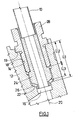
- connection device is intended for sealing between a pipe 10 and a body 12. It is by example of an oil supply pipe for a turbocharger.
- the body 12 includes in particular a bore 14 in communication with an orifice 16 for the circulation of a fluid.
- the bore 14 has a thread 18 over part of its surface.
- the bore has a substantially cylindrical shape with an axis of revolution 20 and of a diameter greater than the diameter of the orifice 16.
- a bearing surface 22 is thus formed between the bore 14 and the orifice 16 due to the reduction in diameter.
- This surface 22 forms the bottom of the bore.
- the bottom 22 of the bore has a frustoconical shape with an apex angle of about 120 °. This shape is obtained during the machining of bore 14.
- this bearing surface 22 can be perpendicular to the axis of revolution 20 of the bore.
- the device comprises a hollow end piece 24 rigidly connected to the pipe 10, a flat annular seal 26 and a hollow retaining screw 28.
- the end piece 24 is described with reference to FIG. 2. It has a symmetry of revolution and external and internal cylindrical shapes in their whole.
- the end piece 24 includes an internal bore 30 of form cylindrical allowing the circulation of the fluid.
- the end piece 24 has a first cylindrical part 32 intended to be inserted into the retaining screw and one end 33 of which is connected rigidly to pipe 10.
- the external diameter of this part is constant over its entire length.
- the internal bore 30 has a diameter slightly greater than the outer diameter of the pipe 10, so that it can be inserted there.
- the link between the pipe and end piece is made by welding, brazing, crimping or similar.
- the internal diameter of the bore 30 then has a diameter smaller than the pipe, so the difference in diameters forms a stop 35 preventing the pipe from penetrating further forward into the nozzle during its assembly.
- the tip has a second cylindrical part 34 integral of the first part 32, of diameter greater than this so that a shoulder 36 is formed by the junction surface between the first and second parts.
- This shoulder 36 extends in a plane substantially perpendicular to the axis of revolution of the parts cylindrical.
- the endpiece has a third cylindrical part 38 integral with the second part 36, of diameter smaller than this. This part 38 is intended to receive the flat seal 26 during assembly of the end piece.
- the junction surface between the second and third parts forms a annular bearing surface 40.
- the end piece is made so that this annular surface 40 is substantially parallel to the bottom 22 of the bore from the body.
- the annular surface thus has a substantially shaped frustoconical, complementary to the shape of the bottom of the bore in the example described.
- the free edge of the third cylindrical part 38 comprises a radial annular projection 42 directed towards the outside of the end piece.
- the flat seal 26, of thickness e has an external diameter less than the smallest internal diameter of the body bore. His internal diameter is substantially equal to the external diameter of the third part 38 of the end piece and less than the diameter of the projection annular 42, so that it is retained by the latter and cannot be accidentally disengage from the nozzle when mounting the device.
- This flat seal 26 is for example made of rubber.
- the retaining screw 28 is described with reference to FIG. 3. It presents a symmetry of revolution and external and internal shapes cylindrical as a whole.
- the screw 28 includes an internal bore 44 of shape cylindrical intended to receive the first cylindrical part 32 of the end piece 24.
- the length of this bore 44 is substantially equal to the length of the first cylindrical part 32 of the end piece (FIG. 1) and the bore 44 has a shape complementary to the part 32.
- the screw 28 has a first cylindrical part 46 carrying a thread 48 on its outer wall intended to cooperate with the thread internal 18 of the bore 14 of the body.
- the surface 52 of the free end 50 of this first part is substantially perpendicular to its axis of revolution. It allows the screw to bear against the shoulder 36 of the nozzle.
- the screw 28 has a second cylindrical part 54 forming a radially projecting shoulder, integral with the first part and diameter greater than this.
- This shoulder allows the screw to take support on the outer edge 19 of the bore.
- the underside 55 of the shoulder is then in abutment against this external edge 19 which is perpendicular to the axis of revolution of the bore.
- the screw 28 has a hexagonal part 56 to its other end, allowing tightening and loosening of the screw by a tool, such as a hexagon wrench for example.
- the length of the bit and the screw and more particularly, the sum of the lengths L2 and L3 is chosen to be less than the length L1 of so as to provide a space between the annular bearing surface 40 and the bottom 22 of the bore. This space allows the housing of the annular seal 26.
- the pipe 10 is introduced into the bore 14 of the retaining screw 28.
- the end of the pipe is then introduced into the end corresponding 33 from the nozzle to the stop 35 and welded to the latter.
- the retaining screw 28 is then brought around the end piece 24, until that the end surface 52 of the screw is in abutment against the shoulder 36 of the nozzle.
- the flat seal 26 is placed on the third cylindrical part 38 of the end piece.
- the assembly is then introduced into the bore 14 of the body by screwing the retaining screw 28 into this bore, until the shoulder 54 of the screw is in contact with the edge external 19 of the bore.
- the seal 26 is thus compressed progressively between the bearing surface 40 of the nozzle and the bottom 22 of the bore of the body. These two surfaces being parallel, the compression of the joint is substantially uniform and distributed over its entire surface, which contributes to increase the life of the seal.
- the retaining screw is finally tightened and locked with a key.
- the thickness e of the joint is chosen so that its crushing is between approximately 10 and 30% (in the case of a rubber seal). These values correspond respectively to the minimum value crushing of the joint necessary to obtain a good seal and the maximum crushing value beyond which a deterioration of the seal and loss of sealing.
- the thickness of the joint takes into account the tolerance intervals for the dimensions following along the axis of revolution: distance L1 between the outer edge 19 and the bottom 22 of the bore of the body, distance L2 between the shoulder 54 and the end 55 of the retaining screw, distance L3 between the shoulder 36 and the annular bearing surface 40 of the nozzle.
- the crash is then substantially equal to half the sum of the intervals of tolerance for these distances.
- this device Used for an oil supply, this device allows withstand a pressure of the order of 5 to 6 bars and a temperature up to 170 ° C.
Landscapes
- Engineering & Computer Science (AREA)
- General Engineering & Computer Science (AREA)
- Mechanical Engineering (AREA)
- Gasket Seals (AREA)
Abstract
Description
- une première partie cylindrique destinée à coopérer avec la vis de maintien et dont une extrémité est solidaire du tuyau,
- une deuxième partie cylindrique solidaire de la première partie, de diamètre supérieur à celle-ci et située à distance du tuyau, un épaulement étant formé par la surface de jonction entre les première et deuxième parties, apte à recevoir l'extrémité de la vis de maintien,
- une troisième partie cylindrique solidaire de la deuxième partie, de diamètre inférieur à celle-ci, destinée à recevoir le joint, la surface de jonction entre les deuxième et troisième parties formant une surface annulaire d'appui pour le joint.
- une première partie cylindrique portant un filetage sur sa paroi externe destiné à coopérer avec le filetage de l'alésage du corps,
- une deuxième partie cylindrique solidaire de la première partie, de diamètre supérieur à celle-ci, formant un épaulement d'appui contre le bord externe de l'alésage du corps.
- la figure 1 est une vue en coupe longitudinale d'un dispositif de raccordement étanche entre un tuyau et l'orifice d'un corps selon l'invention ;
- la figure 2 est une vue en coupe longitudinale de l'embout et du joint du dispositif de la figure 1,
- la figure 3 est une vue en coupe longitudinale de la vis de maintien du dispositif de la figure 1.
Claims (15)
- Dispositif de raccordement étanche entre un tuyau (10) et un orifice (16) d'un corps pour un organe d'admission de fluide d'un véhicule automobile, ledit corps comportant un alésage (14) fileté communiquant avec l'orifice pour la circulation du fluide, ledit dispositif comprenant un embout creux (24) sensiblement cylindrique relié rigidement au tuyau (10), et une vis de maintien creuse (28) sensiblement cylindrique entourant l'embout (24) et destinée à être vissée dans ledit alésage (14) afin de maintenir l'embout (24) coaxialement dans ce dernier, caractérisé en ce que, lorsque la vis de maintien est serrée, un épaulement (54) de la vis de maintien est en butée contre le bord externe (19) de l'alésage et l'extrémité inférieure (50) de la vis dirigée vers l'orifice est en butée contre un épaulement (36) de l'embout, les dimensions de la vis et de l'embout étant telles qu'un espace est ménagé entre l'extrémité libre de l'embout et ledit fond (22) dudit alésage pour loger un joint annulaire, et en ce que l'épaisseur du joint est telle qu'il est alors en appui contre ladite extrémité libre de l'embout et le fond (22) de l'alésage et que son écrasement est compris entre des valeurs minimale et maximale en deçà et au-delà desquelles le joint n'est plus étanche, respectivement.
- Dispositif selon la revendication 1, caractérisé en ce que ladite extrémité libre de l'embout et le fond (22) de l'alésage présentent des surfaces annulaires parallèles destinées à recevoir le joint.
- Dispositif selon l'une des revendications 1 ou 2, caractérisé en ce que le joint annulaire (26) est un joint plat.
- Dispositif selon l'une des revendications 1 à 3, caractérisé en ce que le joint annulaire est en caoutchouc.
- Dispositif selon la revendication 4, caractérisé en ce que l'écrasement du joint est compris entre environ 10 et 30 %.
- Dispositif selon l'une des revendications 1 à 5, caractérisé en ce que le joint présente un diamètre externe sensiblement inférieur au diamètre le plus faible de l'alésage du corps.
- Dispositif selon l'une des revendications 1 à 6, caractérisé en ce que l'extrémité libre de l'embout recevant le joint présente une forme tronconique.
- Dispositif selon la revendication 7 caractérisé en ce que l'angle au sommet de la forme tronconique est d'environ 120°.
- Dispositif selon l'une des revendications 1 à 8, caractérisé en ce que l'épaisseur du joint est telle que son écrasement est sensiblement égal à la moitié de la somme des intervalles de tolérance pour les dimensions suivantes : distance (L1) entre le bord externe et le fond de l'alésage, distance (L2) entre l'épaulement de la vis de maintien et son extrémité inférieure, distance (L3) entre l'épaulement de l'embout et son extrémité libre.
- Dispositif selon l'une des revendications 1 à 9, caractérisé en ce que l'embout (24) comprend notamment :une première partie cylindrique (32) destinée à coopérer avec la vis de maintien (28) et dont une extrémité (33) est solidaire du tuyau,une deuxième partie cylindrique (34), de longueur L3, solidaire de la première partie (32), de diamètre supérieur à celle-ci et située à distance du tuyau, un épaulement (36) étant formé par la surface de jonction entre lesdites première et deuxième parties, apte à recevoir l'extrémité (50) de la vis de maintien,une troisième partie cylindrique (38) solidaire de la deuxième partie (34), de diamètre inférieur à celle-ci, destinée à recevoir le joint, la surface de jonction entre les deuxième et troisième parties formant une surface annulaire d'appui (40) pour le joint.
- Dispositif selon la revendication 10, caractérisé en ce que l'extrémité libre de la troisième partie cylindrique de l'embout comprend une saillie radiale (42) dirigée vers l'extérieur de l'embout.
- Dispositif selon la revendication 11, caractérisé en ce que le diamètre interne du joint est inférieur au diamètre externe de ladite saillie (42).
- Dispositif selon l'une de revendications 1 à 12, caractérisé en ce que la vis de maintien (28) comprend notamment :une première partie cylindrique (46), de longueur L2, portant un filetage (48) sur sa paroi externe destiné à coopérer avec le filetage (18) de l'alésage (14) du corps,une deuxième partie cylindrique (54) solidaire de la première partie, de diamètre supérieur à celle-ci, formant l'épaulement d'appui contre le bord externe (19) de l'alésage du corps.
- Dispositif selon l'une des revendications 1 à 13, caractérisé en ce que la vis de maintien (28) comprend en outre une partie (56) apte à permettre son serrage.
- Dispositif selon l'une des revendications 9 à 14, caractérisé en ce que la somme des longueurs (L2) et (L3) est inférieure à la distance (L1) entre le bord externe et le fond de l'alésage.
Applications Claiming Priority (2)
| Application Number | Priority Date | Filing Date | Title |
|---|---|---|---|
| FR0216315 | 2002-12-20 | ||
| FR0216315A FR2849149B1 (fr) | 2002-12-20 | 2002-12-20 | Dispoisitif de raccordement etanche entre un tuyau et un corps |
Publications (2)
| Publication Number | Publication Date |
|---|---|
| EP1431644A1 true EP1431644A1 (fr) | 2004-06-23 |
| EP1431644B1 EP1431644B1 (fr) | 2006-03-01 |
Family
ID=32338979
Family Applications (1)
| Application Number | Title | Priority Date | Filing Date |
|---|---|---|---|
| EP20030293255 Expired - Lifetime EP1431644B1 (fr) | 2002-12-20 | 2003-12-19 | Dispositif de raccordement étanche entre un tuyau et un corps |
Country Status (4)
| Country | Link |
|---|---|
| EP (1) | EP1431644B1 (fr) |
| DE (1) | DE60303774T2 (fr) |
| ES (1) | ES2254894T3 (fr) |
| FR (1) | FR2849149B1 (fr) |
Citations (5)
| Publication number | Priority date | Publication date | Assignee | Title |
|---|---|---|---|---|
| US2463336A (en) * | 1945-03-15 | 1949-03-01 | Weatherhead Co | Coupling |
| US3025086A (en) * | 1958-02-25 | 1962-03-13 | Compression Joints Ltd | Compression pipe fittings |
| FR2033643A5 (fr) * | 1969-02-28 | 1970-12-04 | Schraubenkombinat K Marx | |
| DE2817438A1 (de) * | 1978-04-21 | 1979-10-25 | Cohnen Gmbh & Co | Rohrverschraubung, insbesondere fuer unter druck stehende kraftstoffleitungen und oelleitungen in kraftfahrzeugen |
| US5553902A (en) * | 1994-07-12 | 1996-09-10 | Powers; Patrick J. | Leak-proof coupling |
-
2002
- 2002-12-20 FR FR0216315A patent/FR2849149B1/fr not_active Expired - Fee Related
-
2003
- 2003-12-19 ES ES03293255T patent/ES2254894T3/es not_active Expired - Lifetime
- 2003-12-19 EP EP20030293255 patent/EP1431644B1/fr not_active Expired - Lifetime
- 2003-12-19 DE DE2003603774 patent/DE60303774T2/de not_active Expired - Lifetime
Patent Citations (5)
| Publication number | Priority date | Publication date | Assignee | Title |
|---|---|---|---|---|
| US2463336A (en) * | 1945-03-15 | 1949-03-01 | Weatherhead Co | Coupling |
| US3025086A (en) * | 1958-02-25 | 1962-03-13 | Compression Joints Ltd | Compression pipe fittings |
| FR2033643A5 (fr) * | 1969-02-28 | 1970-12-04 | Schraubenkombinat K Marx | |
| DE2817438A1 (de) * | 1978-04-21 | 1979-10-25 | Cohnen Gmbh & Co | Rohrverschraubung, insbesondere fuer unter druck stehende kraftstoffleitungen und oelleitungen in kraftfahrzeugen |
| US5553902A (en) * | 1994-07-12 | 1996-09-10 | Powers; Patrick J. | Leak-proof coupling |
Also Published As
| Publication number | Publication date |
|---|---|
| FR2849149A1 (fr) | 2004-06-25 |
| DE60303774T2 (de) | 2006-11-16 |
| FR2849149B1 (fr) | 2005-03-18 |
| DE60303774D1 (de) | 2006-04-27 |
| EP1431644B1 (fr) | 2006-03-01 |
| ES2254894T3 (es) | 2006-06-16 |
Similar Documents
| Publication | Publication Date | Title |
|---|---|---|
| CA2945762C (fr) | Ecrou etanche | |
| EP2817548B1 (fr) | Dispositif de raccordement étanche sans zone de rétention | |
| FR2947592A1 (fr) | Dispositif de liaison mecanique d'au moins deux pieces a alesages coaxiaux | |
| EP0333814A1 (fr) | Raccord a joint metallique annulaire interchangeable | |
| FR2810087A1 (fr) | Element pourvu exterieurement de moyens pour cooperer avec un taraudage | |
| CH657685A5 (fr) | Raccord a action de serrage. | |
| FR2729204A1 (fr) | Agencement de raccord de tubes a moulures doubles, a temperature elevee | |
| EP1431644B1 (fr) | Dispositif de raccordement étanche entre un tuyau et un corps | |
| FR2938038A1 (fr) | Element d'etancheite sans zone de retention et dispositif de raccordement comportant un tel element d'etancheite | |
| EP1020677B1 (fr) | Ensemble de connexion d'une extrémité de conduite à un élément | |
| EP0187608B1 (fr) | Raccord rapide pour circuits de fluide sous pression dont la pression peut atteindre cent cinquante bars | |
| EP0410843B1 (fr) | Embout de raccordement pour tuyau de matière synthétique et procédé de montage | |
| FR2517132A1 (fr) | Dispositif d'etancheite et de serrage pour cables electriques | |
| FR2963077A1 (fr) | Raccord de type banjo a montage rapide, et ensemble comportant un tel raccord | |
| FR2933763A1 (fr) | Raccord hydraulique | |
| FR2890740A1 (fr) | Procede pour essayer en pression un composant filete | |
| FR2634533A1 (fr) | Bague d'etancheite | |
| FR2888307A1 (fr) | Raccord pour robinetterie. | |
| FR2865791A1 (fr) | Dispositif de raccordement pour tuyaux en materiaux deformables | |
| FR3148067A1 (fr) | Réservoir de gaz sous pression, à étanchéité améliorée | |
| EP4098921A1 (fr) | Dispositif de raccordement et appareil comprenant un tel dispositif | |
| JP2023169540A (ja) | 管継手 | |
| FR2773866A1 (fr) | Raccord a souder perfectionne | |
| FR2825774A1 (fr) | Raccords de passage de fluide | |
| FR2783589A1 (fr) | Moyens de raccordement d'une conduite a un corps dans lequel est menage un canal |
Legal Events
| Date | Code | Title | Description |
|---|---|---|---|
| PUAI | Public reference made under article 153(3) epc to a published international application that has entered the european phase |
Free format text: ORIGINAL CODE: 0009012 |
|
| AK | Designated contracting states |
Kind code of ref document: A1 Designated state(s): AT BE BG CH CY CZ DE DK EE ES FI FR GB GR HU IE IT LI LU MC NL PT RO SE SI SK TR |
|
| AX | Request for extension of the european patent |
Extension state: AL LT LV MK |
|
| 17P | Request for examination filed |
Effective date: 20041118 |
|
| GRAP | Despatch of communication of intention to grant a patent |
Free format text: ORIGINAL CODE: EPIDOSNIGR1 |
|
| AKX | Designation fees paid |
Designated state(s): AT BE BG CH CY LI |
|
| RBV | Designated contracting states (corrected) |
Designated state(s): BE DE ES GB IT |
|
| REG | Reference to a national code |
Ref country code: DE Ref legal event code: 8566 |
|
| GRAS | Grant fee paid |
Free format text: ORIGINAL CODE: EPIDOSNIGR3 |
|
| RBV | Designated contracting states (corrected) |
Designated state(s): BE DE ES GB IT |
|
| GRAA | (expected) grant |
Free format text: ORIGINAL CODE: 0009210 |
|
| AK | Designated contracting states |
Kind code of ref document: B1 Designated state(s): BE DE ES GB IT |
|
| REG | Reference to a national code |
Ref country code: GB Ref legal event code: FG4D Free format text: NOT ENGLISH |
|
| GBT | Gb: translation of ep patent filed (gb section 77(6)(a)/1977) |
Effective date: 20060322 |
|
| REF | Corresponds to: |
Ref document number: 60303774 Country of ref document: DE Date of ref document: 20060427 Kind code of ref document: P |
|
| REG | Reference to a national code |
Ref country code: ES Ref legal event code: FG2A Ref document number: 2254894 Country of ref document: ES Kind code of ref document: T3 |
|
| PLBE | No opposition filed within time limit |
Free format text: ORIGINAL CODE: 0009261 |
|
| STAA | Information on the status of an ep patent application or granted ep patent |
Free format text: STATUS: NO OPPOSITION FILED WITHIN TIME LIMIT |
|
| 26N | No opposition filed |
Effective date: 20061204 |
|
| PGFP | Annual fee paid to national office [announced via postgrant information from national office to epo] |
Ref country code: IT Payment date: 20121219 Year of fee payment: 10 |
|
| PGFP | Annual fee paid to national office [announced via postgrant information from national office to epo] |
Ref country code: BE Payment date: 20121219 Year of fee payment: 10 |
|
| BERE | Be: lapsed |
Owner name: *RENAULT S.A.S. Effective date: 20131231 |
|
| PG25 | Lapsed in a contracting state [announced via postgrant information from national office to epo] |
Ref country code: BE Free format text: LAPSE BECAUSE OF NON-PAYMENT OF DUE FEES Effective date: 20131231 |
|
| PG25 | Lapsed in a contracting state [announced via postgrant information from national office to epo] |
Ref country code: IT Free format text: LAPSE BECAUSE OF NON-PAYMENT OF DUE FEES Effective date: 20131231 |
|
| PGFP | Annual fee paid to national office [announced via postgrant information from national office to epo] |
Ref country code: DE Payment date: 20151211 Year of fee payment: 13 Ref country code: GB Payment date: 20151221 Year of fee payment: 13 |
|
| PGFP | Annual fee paid to national office [announced via postgrant information from national office to epo] |
Ref country code: ES Payment date: 20151214 Year of fee payment: 13 |
|
| PG25 | Lapsed in a contracting state [announced via postgrant information from national office to epo] |
Ref country code: IT Free format text: LAPSE BECAUSE OF NON-PAYMENT OF DUE FEES Effective date: 20131219 |
|
| REG | Reference to a national code |
Ref country code: DE Ref legal event code: R119 Ref document number: 60303774 Country of ref document: DE |
|
| GBPC | Gb: european patent ceased through non-payment of renewal fee |
Effective date: 20161219 |
|
| PG25 | Lapsed in a contracting state [announced via postgrant information from national office to epo] |
Ref country code: DE Free format text: LAPSE BECAUSE OF NON-PAYMENT OF DUE FEES Effective date: 20170701 Ref country code: GB Free format text: LAPSE BECAUSE OF NON-PAYMENT OF DUE FEES Effective date: 20161219 |
|
| PG25 | Lapsed in a contracting state [announced via postgrant information from national office to epo] |
Ref country code: ES Free format text: LAPSE BECAUSE OF NON-PAYMENT OF DUE FEES Effective date: 20161220 |
|
| REG | Reference to a national code |
Ref country code: ES Ref legal event code: FD2A Effective date: 20181116 |