EP1431618A2 - Transmission for wheel type working vehicle - Google Patents
Transmission for wheel type working vehicle Download PDFInfo
- Publication number
- EP1431618A2 EP1431618A2 EP03017078A EP03017078A EP1431618A2 EP 1431618 A2 EP1431618 A2 EP 1431618A2 EP 03017078 A EP03017078 A EP 03017078A EP 03017078 A EP03017078 A EP 03017078A EP 1431618 A2 EP1431618 A2 EP 1431618A2
- Authority
- EP
- European Patent Office
- Prior art keywords
- output shaft
- transmission mechanism
- power
- hydraulic
- rear wheel
- Prior art date
- Legal status (The legal status is an assumption and is not a legal conclusion. Google has not performed a legal analysis and makes no representation as to the accuracy of the status listed.)
- Granted
Links
Images


Classifications
-
- F—MECHANICAL ENGINEERING; LIGHTING; HEATING; WEAPONS; BLASTING
- F16—ENGINEERING ELEMENTS AND UNITS; GENERAL MEASURES FOR PRODUCING AND MAINTAINING EFFECTIVE FUNCTIONING OF MACHINES OR INSTALLATIONS; THERMAL INSULATION IN GENERAL
- F16H—GEARING
- F16H47/00—Combinations of mechanical gearing with fluid clutches or fluid gearing
- F16H47/02—Combinations of mechanical gearing with fluid clutches or fluid gearing the fluid gearing being of the volumetric type
- F16H47/04—Combinations of mechanical gearing with fluid clutches or fluid gearing the fluid gearing being of the volumetric type the mechanical gearing being of the type with members having orbital motion
-
- B—PERFORMING OPERATIONS; TRANSPORTING
- B60—VEHICLES IN GENERAL
- B60K—ARRANGEMENT OR MOUNTING OF PROPULSION UNITS OR OF TRANSMISSIONS IN VEHICLES; ARRANGEMENT OR MOUNTING OF PLURAL DIVERSE PRIME-MOVERS IN VEHICLES; AUXILIARY DRIVES FOR VEHICLES; INSTRUMENTATION OR DASHBOARDS FOR VEHICLES; ARRANGEMENTS IN CONNECTION WITH COOLING, AIR INTAKE, GAS EXHAUST OR FUEL SUPPLY OF PROPULSION UNITS IN VEHICLES
- B60K17/00—Arrangement or mounting of transmissions in vehicles
- B60K17/04—Arrangement or mounting of transmissions in vehicles characterised by arrangement, location, or kind of gearing
- B60K17/10—Arrangement or mounting of transmissions in vehicles characterised by arrangement, location, or kind of gearing of fluid gearing
- B60K17/105—Units comprising at least a part of the gearing and a torque-transmitting axle, e.g. transaxles
-
- B—PERFORMING OPERATIONS; TRANSPORTING
- B60—VEHICLES IN GENERAL
- B60K—ARRANGEMENT OR MOUNTING OF PROPULSION UNITS OR OF TRANSMISSIONS IN VEHICLES; ARRANGEMENT OR MOUNTING OF PLURAL DIVERSE PRIME-MOVERS IN VEHICLES; AUXILIARY DRIVES FOR VEHICLES; INSTRUMENTATION OR DASHBOARDS FOR VEHICLES; ARRANGEMENTS IN CONNECTION WITH COOLING, AIR INTAKE, GAS EXHAUST OR FUEL SUPPLY OF PROPULSION UNITS IN VEHICLES
- B60K5/00—Arrangement or mounting of internal-combustion or jet-propulsion units
- B60K5/04—Arrangement or mounting of internal-combustion or jet-propulsion units with the engine main axis, e.g. crankshaft axis, transversely to the longitudinal centre line of the vehicle
-
- Y—GENERAL TAGGING OF NEW TECHNOLOGICAL DEVELOPMENTS; GENERAL TAGGING OF CROSS-SECTIONAL TECHNOLOGIES SPANNING OVER SEVERAL SECTIONS OF THE IPC; TECHNICAL SUBJECTS COVERED BY FORMER USPC CROSS-REFERENCE ART COLLECTIONS [XRACs] AND DIGESTS
- Y10—TECHNICAL SUBJECTS COVERED BY FORMER USPC
- Y10T—TECHNICAL SUBJECTS COVERED BY FORMER US CLASSIFICATION
- Y10T74/00—Machine element or mechanism
- Y10T74/19—Gearing
- Y10T74/19023—Plural power paths to and/or from gearing
- Y10T74/19037—One path includes fluid drive
Definitions
- the present invention relates to a transmission for a wheel type working vehicle, and particularly relates to a transmission for a wheel type working vehicle capable of selectively transmitting a mechanical driving force and a hydraulic driving force to differential devices of front and rear wheels of the vehicle with an engine and the transmission being integrally connected and mounted on a lower part of a vehicle chassis frame.
- a wheel type working vehicle in which a driving unit, in which an engine, and a mechanical-hydraulic transmission (hereinafter, simply called a transmission) capable of selectively switching a mechanical driving force and a hydraulic driving force by switching a clutch in accordance with traveling ranges of a plurality of gears are integrally connected without interposing a torque converter, is placed on a lower part of a chassis frame, is proposed, and the one is disclosed in, for example, patent document 1.
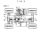
- FIG. 5 and FIG. 6 is a plane view of a base carrier of a wheel type working vehicle disclosed in patent document 1, and a schematic view of its power train.
- patent document 1 is Japanese Patent Laid-open No. 2002-362174, and the wheel type working vehicle is disclosed especially on pages 5 to 6, FIG. 1, and FIG. 3.
- an engine 80 is placed at a right side of a chassis frame 81 with its output shaft axis C-C facing in a lateral direction of the vehicle.
- a transmission 82 is placed on a lower part in the chassis frame 81 in a direction of an output shaft 81a of the engine 80.
- the output shaft 80a of the engine 80 is integrally connected to the transmission 82.
- a front and rear wheel driving output shaft 98 having a rear output shaft 98a and a front output shaft 98b is placed in a longitudinal direction of the vehicle at a left side of the transmission 82.
- the rear output shaft 98a and the front output shaft 98b are connected to a rear and a front wheel axles 85a and 85b via propeller shafts 95a and 95b, and differential devices 86a and 86b, respectively.
- the transmission 82 includes a first input shaft 87 connected to the output shaft of the engine 80, a first intermediate shaft 88, and an output shaft 89 (shown by an output shaft axis E-E in FIG. 5) to be in parallel.
- the shafts 87, 88 and 89 arc provided respectively with a deceleration gear train 90 and speed change gear clutches 92, 93 and 94.
- Power of the engine 80 is mechanically shifted and transmitted to the output shaft 89 via the deceleration gear train 90 and each of the speed change gear clutches 92, 93 and 94.
- the transmission 82 includes a second input shaft 96, and a second intermediate shaft 97.
- a hydraulic motor 84 which receives discharge oil of a hydraulic pump 83 connected to an opposite side from the engine 80 in the first input shaft 87 and is rotationally driven via a control valve (not shown), is connected to the second input shaft 96.
- the second input shaft 96 and the second intermediate shaft 97 are provided with a deceleration gear train 99 and a speed change gear clutch 91.
- a hydraulic driving force of the hydraulic motor 84 is transmitted to the output shaft 89 via the deceleration gear train 99 and the speed change gear clutch 91.
- a shaft 101 provided with a bevel gear 102 is connected to the output shaft 89, and the bevel gear 102 is meshed with a bevel gear 103 provided at the rear output shaft 98a.
- An output power of the output shaft 89 of the transmission 82 is transmitted to the rear output shaft 98a via the bevel gears 102 and 103.
- the rear output shaft 98a is selectively connected to the front output shaft 98b via a mechanical clutch mechanism 104.
- the speed change gear clutch 91 when only the speed change gear clutch 91 is engaged, the speed is in a low-speed traveling range of a first speed gear, and the driving force of the hydraulic motor 84 is outputted from the output shaft 89 via the deceleration gear train 99 and the second intermediate shaft 97.
- the speed change gear clutches 92, 93, and 94 are individually engaged respectively, the speed is in a high-speed traveling range of the second, third and fourth speed gear, and the driving force of the engine 80 is outputted from the output shaft 89 via the deceleration gear train 90 and the first intermediate shaft 88.
- the mechanical driving force and the hydraulic driving force are constituted so as to be outputted from the common output shaft 89.
- the mechanical driving force and the hydraulic driving force are outputted to the front and rear wheel driving output shaft 98 via the common output shaft 89 and the bevel gears 102 and 103.
- the output shaft 89 and the bevel gears 102 and 103 have to transmit a hydraulic driving power with a large torque capacity, and therefore it becomes necessary to increase the output shaft 89 and the bevel gears 102 and 103 in size, thus causing the problem of the entire transmission becoming large.
- the present invention is made in view of the above-described problems, and has its object to provide a transmission for a wheel type working vehicle which makes it possible to reduce a size of a transmission mechanism for transmitting a mechanical driving force and a hydraulic driving force from the transmission to a front and rear wheel driving output shaft along a vehicle longitudinal direction in a wheel type working vehicle in which rotation axes of the engine and the transmission are placed in a direction orthogonal to the vehicle longitudinal direction.
- a transmission of a wheel type working vehicle has: in a transmission for a wheel type working vehicle in which a mechanical transmission mechanism for mechanically transmitting power, and a hydraulic power transmission mechanism having a hydraulic pump and a hydraulic motor driven by the hydraulic pump to transmit hydraulic transmission power are provided side by side as power transmission mechanisms for transmitting power of an engine to front and rear wheels via a front and rear wheel driving output shaft; a constitution in that an output shaft of the mechanical transmission mechanism is provided in a direction orthogonal to a vehicle longitudinal direction; the front and rear wheel driving output shaft and an output shaft of the hydraulic power transmission mechanism are provided in the vehicle longitudinal direction; power from the output shaft of the mechanical transmission mechanism is transmitted to the front and rear wheel driving output shaft via a bevel gear transmission mechanism; and power from the output shaft of the hydraulic power transmission mechanism is transmitted to the front and rear wheel driving output shaft via a cylindrical gear transmission mechanism.
- the mechanical driving force from the output shaft of the mechanical transmission mechanism is transmitted to the front and rear driving output shaft for transmitting the power to the front and rear wheels via the bevel gear transmission mechanism.
- the hydraulic driving force being driving with large torque at a low speed by the hydraulic motor of the hydraulic power transmission mechanism is directly transmitted via the cylindrical gear transmission mechanism without transmitted via the bevel gear transmission mechanism, and therefore the bevel gear transmission mechanism can be reduced in size.
- the bevel gear transmission mechanism may mesh a bevel gear provided at the front and rear wheel driving output shaft with a bevel gear connected to the output shaft of the mechanical transmission mechanism; and the cylindrical gear transmission mechanism may mesh a cylindrical gear provided at the front and rear wheel driving output shaft with a cylindrical gear provided at the output shaft of the hydraulic power transmission mechanism.
- the front and rear wheel driving output shaft is equipped with the bevel gear of the bevel gear transmission mechanism and the cylindrical gear of the cylindrical gear transmission mechanism, and therefore the power from the output shaft of the mechanical transmission mechanism and the power from the output shaft of the hydraulic power transmission mechanism are directly transmitted to the front and rear wheel driving output shaft, thus making it possible to enhance the transmission efficiency. Since the front and rear wheel driving output shaft is constituted by one shaft, the constitution can be made compact.
- a mechanical transmission housing which rotatably houses the output shaft of the mechanical transmission mechanism, and to which the hydraulic pump is mounted
- a power output housing which rotatably houses the front and rear wheel driving output shaft and the output shaft of the hydraulic power transmission mechanism, and to which the hydraulic motor is mounted
- the mechanical transmission housing and the power output housing may be constituted to be separate bodies, and may be integrally mounted to be attachable and detachable.
- the power output housing which rotatably houses the front and rear wheel driving output shaft and the output shaft of the hydraulic power transmission mechanism is constituted to be a separate body from the mechanical transmission housing which rotatably houses the output shaft of the mechanical transmission mechanism, and is integrally mounted to the mechanical transmission housing with a bolt or the like to be attachable and detachable, and therefore production of the mechanical transmission housing and the power output housing is facilitated.
- the front and rear wheel driving output shaft may comprise a rear wheel driving output shaft which has the bevel gear and the cylindrical gear and always transmits rotating power to the rear wheels, and a front wheel driving output shaft which is selectively separated from or connected to the rear wheels driving output shaft via a clutch mechanism, and selectively transmits the rotating power to the front wheels; and the clutch mechanism may make it possible to switch between two drive and four drive.
- traveling power of the hydraulic drive traveling and the mechanical drive traveling can be selectively transmitted to the rear wheels (two drive), or the front and rear wheels (four drive), and traveling according to the conditions of the traveling areas and working conditions can be selected.
- the rear wheel driving output shaft may be fitted to a rotating supporter at a rear wheel side via a first bearing; the front wheel driving output shaft may be fitted to a rotating supporter at a front wheel side via a second bearing; and the rotating supporters at the rear wheel side and the front wheel side may be respectively mounted to the power output housing to be attachable and detachable.
- the rear wheel driving output shaft and the front wheel driving output shaft can be attached to and detached from the power output housing as units via the rotating supporters, respectively, and therefore assembly and disassembly are facilitated.
- the hydraulic power transmission mechanism may comprise a planetary gear type deceleration mechanism for stopping rotation of a ring gear by engagement of a hydraulic operating clutch, and outputting rotating power of the hydraulic motor from a planetary carrier via a sun gear included at an input shaft connected to an output shaft of the hydraulic motor by rotation and revolution of a planetary gear, and the output shaft of the hydraulic power transmission mechanism, which is provided on a same axis as that of the input shaft and integrally connected to the planetary carrier.
- the hydraulic power transmission mechanism has the planetary gear type deceleration mechanism, and the output shaft of the hydraulic power transmission mechanism is integrally connected to the center of rotation of the planetary carrier of the planetary gear type deceleration mechanism, and therefore the hydraulic power transmission mechanism becomes compact in the radius direction.
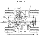
- FIG. 1 is a partial sectional plane view of a base carrier of a wheel type working vehicle according to the embodiment and FIG. 2 is a view seen from the arrows A to A in FIG. 1.
- the explanation will be made, citing an example of a wheel type hydraulic shovel in which an upper revolving superstructure mounted with a working machine is rotatably loaded on a base carrier, as the wheel type working vehicle.
- the wheel type hydraulic shovel has front wheels 13 and 13, and rear wheels 14 and 14 on the left and the right of lower front and rear parts of the base carrier 1, and an upper revolving superstructure 3 mounted with a working machine (not shown) constituted of a boom, an arm, a bucket and the like is rotatably loaded on an upper part of the base carrier 1.
- An engine 11 is mounted at either a left or right side position on a lower part of a chassis frame 10 of the base carrier 1 to be laterally placed with an engine output shaft axis C-C being in a direction orthogonal to a vehicle longitudinal direction (namely, a center line X-X in a vehicle longitudinal direction in the drawing).
- a transmission 12 is integrally connected to the engine 11, and the transmission 12 is housed in a lower part of an inside of the chassis frame 10.
- a hydraulic pump 16 is mounted to an input shaft of the transmission 12, which is located on an extension line of the engine output shaft axis C-C, at an opposite side from the engine 11.
- An output shaft of a mechanical transmission mechanism 15 (hereinafter, called a transmission mechanism 15) of the transmission 12 is parallel with an input shaft of the transmission 12 (an axis of the input shaft is shown by the alternate long and short dash line in the drawing), and is provided at a position (the alternate long and short dash line in the drawing) at a predetermined space from the input shaft in the longitudinal direction of the vehicle.
- a bevel gear transmission mechanism 22 (hereinafter, called a bevel gear mechanism 22) is connected to this output shaft.
- the bevel gear mechanism 22 is for converting a power transmitting direction by the transmission mechanism 15 into the vehicle longitudinal direction from the direction of the engine output shaft axis C-C.
- a front and a rear wheel propeller shafts 18 and 19 are connected to a power output shaft (namely, a front and rear wheel driving output shaft 20) of the bevel gear mechanism 22, which is converted, via a propeller shaft joints 48 and 47.
- a hydraulic power transmission mechanism 24 meshed with the power output shaft with a cylindrical gear mechanism is placed at a side of the bevel gear mechanism 22.
- a hydraulic motor 17 is connected to an input shaft of the hydraulic power transmission mechanism 24. The rotational frequency of the hydraulic motor 17 is controlled by switching pressure oil discharged from a hydraulic pump 16 with a control valve (not shown).
- the transmission 12 has the transmission mechanism 15 for transmitting mechanical transmission power to the front and rear wheels 13 and 14 of the wheel type working vehicle, the variable displacement type hydraulic pump 16 mounted to the transmission mechanism 15 and connected to the engine 11, the variable displacement type hydraulic motor 17 driven by the discharge oil from the hydraulic pump 16 to output hydraulic transmission power, and the front and rear wheel driving output shaft 20 (hereinafter, called the driving output shaft 20) for transmitting a mechanical driving power by the transmission mechanism 15 and hydraulic driving power by the hydraulic motor 17 to the front and rear wheel propeller shafts 18 and 19.
- the driving output shaft 20 is placed in the direction orthogonal to the output shaft 21 of the transmission mechanism 15, and is connected to the output shaft 21 via the bevel gear mechanism 22.
- the hydraulic power transmission mechanism 24 to which the hydraulic motor 17 is connected has a planetary gear type speed reducer provided at its input shaft, and an output shaft 23 connected to the planetary gear type speed reducer and mounted with a cylindrical gear 53 (a spur gear in this example).
- An axis direction of the output shaft 23 is placed in a direction parallel with an axis direction of the driving output shaft 20.
- the cylindrical gear 53 of the output shaft 23 is meshed with a cylindrical gear 50 (a spur gear in this example) mounted to the driving output shaft 20 to constitute a cylindrical gear transmission mechanism 25. According to this, the hydraulic driving force by the hydraulic motor 17 is transmitted to the driving output shaft 20 via the cylindrical gear transmission mechanism 25.
- the transmission mechanism 15 includes an input shaft 26, an intermediate shaft 27 and an output shaft 21 rotatably inside a transmission housing 39 in directions orthogonal to the vehicle longitudinal direction (namely, an axis direction of the driving output shaft 20) and substantially horizontal.
- the input shaft 26, the intermediate shaft 27 and the output shaft 21 are placed in parallel with each other with a space from each other.
- the input shaft 26, the intermediate shaft 27 and the output shaft 21 are respectively provided with the transmission clutches 28, 29 and 30, and fixed gears 31, 32 and 33 fixed at the respective shafts, and free gears 34, 35 and 36 fitted to the respective shafts with play.
- a multiple shaft type mechanical transmission mechanism is constituted of these components.
- the multiple shaft type mechanical transmission mechanism is constituted by meshing the fixed gear 31 of the input shaft 26 with the fixed gear 32 of the intermediate shaft 27, and the free gear 34 with the free gear 35, meshing the fixing gear 32 of the intermediate shaft 27 with the free gear 36 of the output shaft 21, and meshing the free gear 35 of the intermediate shaft 27 with the fixed gear 33 of the output shaft 21. According to this, the multiple shaft type mechanical transmission mechanism with forward three gears is provided.
- the input shaft fixed gear 31 and the input shaft free gear 34 are connected to output the mechanical driving force of a specified deceleration ratio is outputted to the output shaft 21 via the intermediate shaft free gear 35 meshed with the input shaft free gear 34, and the output shaft fixed gear 33 meshed with the intermediate shaft free gear 35.
- the above-described multiple shaft type mechanical transmission mechanism is connected to an engine output shaft 11a via a torque damper joint 37 included at the input shaft 26, and the transmission housing 39 housing the input shaft 26, the intermediate shaft 27 and the output shaft 21 to be spaced from each other is connected to an engine housing 40 to be laid in the vehicle longitudinal direction, whereby the engine 11 and the transmission 12 are integrated.
- the transmission housing 39 has a mechanical transmission housing 41 provided extensively in the vehicle longitudinal direction, and a power output housing 42 provided extensively in a direction orthogonal to the vehicle longitudinal direction.
- the housings 41 and 42 are formed to be separate bodies respectively, and connected to each other in substantially a L-shape in plane view.
- the mechanical transmission housing 41 contains the transmission mechanism 15 and has a pump mounting seat 43 around an area where the input shaft 26 of the transmission mechanism 15 faces an outside.
- An input shaft 44 of the hydraulic pump 16 is connected to the input shaft 26, and the hydraulic pump 16 is mounted to the mechanical transmission housing 41 with a hydraulic pump housing mounting part being placed on the pump mounting seat 43.
- the mechanical transmission housing 41 has a housing mounting seat 45 around an area where the output shaft 21 of the transmission mechanism 15 faces the outside.
- the power output housing 42 is placed in the state in which it extends in the axis direction of the output shaft 21, and mounted to the housing mounting seat 45.
- a bevel gear 46 at an input side of the bevel gear mechanism 22, which connects to the output shaft 21, is rotatably placed at an entrance side of the housing in the power output housing 42.
- the driving output shaft 20 is rotataly mounted such that the axis direction of the driving output shaft 20 is orthogonal to the axis direction of the output shaft 21 of the transmission mechanism 15, and is disposed in the vehicle longitudinal direction.
- the hydraulic power transmission mechanism 24 connected to the hydraulic motor 17 is placed in the power output housing 42 in the direction in which the axis direction of the mechanism 24 is parallel with the axis of the driving output shaft 20.
- the driving output shaft 20 includes the propeller shaft joints 47 and 48 at the front and rear end portions, a bevel gear 49 at an output side of the bevel gear mechanism 22, and the cylindrical gear 50 at one side of the cylindrical gear transmission mechanism 25.
- the propeller shaft joints 47 and 48 are respectively connected to the front wheel propeller shaft 18 and the rear wheel propeller shaft 19 respectively connected to a front wheel differential device 52 and a rear wheel differential device 52 as shown in FIG. 3.
- the bevel gear 49 is meshed with the bevel gear 46 provided in the power output housing 42, so that the mechanical driving force from the transmission mechanism 15 is transmitted to the driving output shaft 20.
- the cylindrical gear 50 is meshed with the cylindrical gear 53 provided at the output shaft 23 of the hydraulic power transmission mechanism 24, so that the hydraulic driving force by the hydraulic motor 17 is transmitted to the driving output shaft 20.
- the driving output shaft 20 is divided into a rear wheel driving output shaft 54 including the bevel gear 49 and the cylindrical gear 50 for transmitting and outputting rotating power to the rear wheels, and a front wheel driving output shaft 55 for transmitting and outputting the rotating power to the front wheels.
- a female and male engaging part 56 (see FIG. 4) is formed on opposing end surface at which the front wheel driving output shaft 55 and the rear wheel driving output shaft 54 face each other, and the front wheel driving output shaft 55 is matched to the rear wheel driving output shaft 54 in the state in which it is freely rotated with respect to the rear wheel driving output shaft 54.
- the front wheel driving output shaft 55 is constituted to connect to the rear wheel driving output shaft 54 selectively via a jaw clutch mechanism 57, thereby making it possible to switch between the second drive and the fourth drive.
- the jaw clutch mechanism 57 is engaged with an outer circumference surface of the front wheel driving output shaft 55 by spline and slidable in an axial direction.
- the jaw clutch mechanism 57 has a cylinder clutch 59 having an engaging claw 58 in a convex shape in a diameter direction at its opposing end surface to the rear wheel driving output shaft 54, a spring 60, which is provided between a stepped end surface of an outer circumference surface of the front wheel driving output shaft 55 and a stepped end surface of an outer circumference surface of the cylinder clutch 59, and biases the cylinder clutch 59 in a direction toward the rear wheel driving output shaft 54, an annular claw 61 in a convex shape in a diameter direction, which is formed at an end surface of the rear wheel driving output shaft 54 opposing the engaging claw 58 of the cylinder clutch 59, and a hydraulic pressure receiving chamber 62 for moving the cylinder clutch 59, which is formed between an inner circumference surface of the cylinder clutch 59 and the outer circumference surface of the front wheel driving
- An oil path communicating with the hydraulic pressure receiving chamber 62 is formed inside the front wheel driving output shaft 55.
- the cylinder clutch 59 overcomes the biasing force of the spring 60 and moves downward in FIG. 4.
- the left half surface of the cylinder clutch 59 shows a descending state. Due to this, engagement of the engaging claw 58 of the cylinder clutch 59 and the annular claw 61 of the rear wheel driving output shaft 54 is released.
- the rear wheel driving output shaft 54 is rotatably supported by a rotating supporter 64 having a taper cylindrical bearing (first bearing) 63.
- the front wheel driving output shaft 55 is rotatably supported by a rotating supporter 66 having a ball bearing (second bearing) 65.
- Tow openings 67 and 68 are coaxially formed to oppose each other in the power output housing 42, and the rotating supporter 64 is mounted to the one opening 67 to position the rear wheel driving output shaft 54 rotataly with respect to the power output housing 42.
- the rotating supporter 66 is mounted to the other opening 68 to position the front wheel driving output shaft 55 rotatably with respect to the power output housing 42.
- the hydraulic power transmission mechanism 24 connected to the hydraulic motor 17 has a carrier output type of planetary gear deceleration mechanism, and the output shaft 23 with a cylindrical gear 53, which is integrally connected to an output carrier of the planetary gear deceleration mechanism.
- the planetary gear deceleration mechanism has a sun gear 70 attached to an input shaft 71 connected to an output shaft 69 of the hydraulic motor 17, a ring gear 72 and a planetary carrier 73 held at the input shaft 71 to be freely rotatable, a planetary gear 74 supported by the planetary carrier 73 and meshed with the sun gear 70 and a ring gear 72, and a hydraulically operating clutch 77 provided between a clutch inner cylinder 75 integrally formed at the ring gear 72 and a clutch outer cylinder 76 fixed at the power output housing 42.
- Rotation of the ring gear 72 is stopped by engagement of the hydraulically operating clutch 77, and the rotating power of the hydraulic motor 17 is outputted from the planetary carrier 73 by rotation and revolution of the planetary gear 74.
- the output shaft 23 is positioned in the axial direction of the input shaft 71, and rotatably held by the power output housing 42.
- the hydraulic motor 17 has its output shaft 69 placed coaxially with the axis direction of the input shaft 71 and the output shaft 23 of the planetary gear reducer, and is mounted to a motor mounting part 78 included in the power output housing 42.
- the transmission according to the present invention performs a normal and reverse rotation control of the hydraulic motor 17 to engage the hydraulically operating clutch 77 of the hydraulic power transmission mechanism 24 connected to the output shaft 69 of the hydraulic motor 17.
- a hydraulic driving force of the forward and reverse first speed gear is transmitted to the front and rear wheel driving output shafts 55 and 54 via the san gear 70, the planetary gear 74, and the planetary carrier 73 of the planetary gear deceleration mechanism, and the output shaft 23 and the cylindrical gear 53.
- the transmission system of the hydraulic driving force by the hydraulic motor is made independent from the power transmission system of the mechanical transmission mechanism, and an exclusive hydraulic power transmission mechanism is provided.
- the mechanical driving force from the output shaft of the mechanical transmission mechanism is transmitted to the front and rear wheel driving output shaft for transmitting the power to the front and rear wheels via the bevel gear transmission mechanism. Consequently, the hydraulic driving force being large torque drive at a low speed by the hydraulic motor of the hydraulic power transmission mechanism is directly transmitted via the cylindrical gear transmission mechanism without being transmitted via the bevel gear transmission mechanism, and therefore the bevel gear transmission mechanism can be made compact.
- the bevel gear of the bevel gear transmission mechanism and the cylindrical gear of the cylindrical gear transmission mechanism are included at the front and rear wheel driving output shaft. Consequently, the power from the output shaft of the mechanical transmission mechanism and the power from the output shaft of the hydraulic power transmission mechanism are directly transmitted to the front and rear driving output shaft without being transmitted via the intermediate shaft, and therefore the transmission efficiency can be made higher.
- the front and rear wheel driving output shaft is constituted of one shaft, and therefore it can be made compact.
- the power output housing for rotatably housing the front and rear wheel driving output shaft and the output shaft of the hydraulic power transmission mechanism is constituted to be a separate body from the mechanical transmission housing for rotatably housing the output shaft of the mechanical transmission mechanism, and the power output housing is integrally mounted to the mechanical transmission housing with a bolt or the like to be attachable and detachable. Consequently, production of the mechanical transmission housing and the power output housing is facilitated.
- the mechanical transmission housing is laid in a direction along the vehicle longitudinal direction, and the power output housing is extensively provided in the direction orthogonal to the vehicle longitudinal direction (namely, the vehicle side direction), which are placed in substantially a L-shape in plane view. Consequently, it is possible to position the axis direction of the front and rear wheel driving output shaft, which is placed. in the housing, in the vehicle longitudinal direction, and the front and rear propeller shafts connected to the front and rear driving force output shaft can be also placed in the vehicle longitudinal direction. According to this constitution, the length of the front and rear wheel output shaft can be reduced though the mechanical transmission mechanism part is in a long shape in the vehicle longitudinal direction, and the length of the propeller shaft connected to the front and rear wheel output shaft can be made relatively long. As a result, cross angles of the front and rear propeller shafts and the front and rear wheel axels can be prevented from being large, and therefore the driving force can be efficiently transmitted to the front and rear wheel axels.
- the front and rear driving output shaft is divided into the front wheel driving output shaft and the rear wheel driving output shaft, and the portion between both the output shafts is selectively separated and connected via the clutch.
- the two drive to four drive switching type of rear wheel driving output shaft is mounted on the rotating supporter having the bearing (the taper cylindrical bearing in the above-described embodiment is one example), and the front wheel driving output shaft is mounted on the rotating supporter having the bearing (the ball bearing in the above-described embodiment is one example).
- the rotating supporters of the rear wheel driving output shaft and the front wheel driving output shaft are mounted in the two openings formed to oppose the power output housing coaxially to be attachable and datable respectively.
- the two drive to four drive switching type of rear wheel driving output shaft and the front wheel driving output shaft, and the bevel gear connected to the output shaft of the mechanical transmission mechanism can be mounted to and dismounted from the power output housing as units via the rotating supporters, respectively, and therefore assembly and disassembly are facilitated.
- the hydraulic power transmission mechanism includes the planetary gear type deceleration mechanism, and the output shaft integrally connected to the rotation center of the planetary carrier of the planetary gear type deceleration mechanism, and therefore the hydraulic power transmission mechanism becomes compact in the radius direction.
Abstract
Description
- The present invention relates to a transmission for a wheel type working vehicle, and particularly relates to a transmission for a wheel type working vehicle capable of selectively transmitting a mechanical driving force and a hydraulic driving force to differential devices of front and rear wheels of the vehicle with an engine and the transmission being integrally connected and mounted on a lower part of a vehicle chassis frame.
- A wheel type working vehicle, in which a driving unit, in which an engine, and a mechanical-hydraulic transmission (hereinafter, simply called a transmission) capable of selectively switching a mechanical driving force and a hydraulic driving force by switching a clutch in accordance with traveling ranges of a plurality of gears are integrally connected without interposing a torque converter, is placed on a lower part of a chassis frame, is proposed, and the one is disclosed in, for example,
patent document 1. FIG. 5 and FIG. 6 is a plane view of a base carrier of a wheel type working vehicle disclosed inpatent document 1, and a schematic view of its power train. Here,patent document 1 is Japanese Patent Laid-open No. 2002-362174, and the wheel type working vehicle is disclosed especially on pages 5 to 6, FIG. 1, and FIG. 3. - In FIG. 5 and FIG. 6, an
engine 80 is placed at a right side of achassis frame 81 with its output shaft axis C-C facing in a lateral direction of the vehicle. Atransmission 82 is placed on a lower part in thechassis frame 81 in a direction of an output shaft 81a of theengine 80. Theoutput shaft 80a of theengine 80 is integrally connected to thetransmission 82. A front and rear wheeldriving output shaft 98 having arear output shaft 98a and afront output shaft 98b is placed in a longitudinal direction of the vehicle at a left side of thetransmission 82. Therear output shaft 98a and thefront output shaft 98b are connected to a rear and afront wheel axles propeller shafts differential devices - The
transmission 82 includes afirst input shaft 87 connected to the output shaft of theengine 80, a first intermediate shaft 88, and an output shaft 89 (shown by an output shaft axis E-E in FIG. 5) to be in parallel. Theshafts deceleration gear train 90 and speedchange gear clutches engine 80 is mechanically shifted and transmitted to theoutput shaft 89 via thedeceleration gear train 90 and each of the speedchange gear clutches transmission 82 includes asecond input shaft 96, and a secondintermediate shaft 97. Ahydraulic motor 84, which receives discharge oil of ahydraulic pump 83 connected to an opposite side from theengine 80 in thefirst input shaft 87 and is rotationally driven via a control valve (not shown), is connected to thesecond input shaft 96. Thesecond input shaft 96 and the secondintermediate shaft 97 are provided with adeceleration gear train 99 and a speedchange gear clutch 91. A hydraulic driving force of thehydraulic motor 84 is transmitted to theoutput shaft 89 via thedeceleration gear train 99 and the speedchange gear clutch 91. - A
shaft 101 provided with abevel gear 102 is connected to theoutput shaft 89, and thebevel gear 102 is meshed with abevel gear 103 provided at therear output shaft 98a. An output power of theoutput shaft 89 of thetransmission 82 is transmitted to therear output shaft 98a via thebevel gears rear output shaft 98a is selectively connected to thefront output shaft 98b via amechanical clutch mechanism 104. - According to the above-described constitution, when only the speed
change gear clutch 91 is engaged, the speed is in a low-speed traveling range of a first speed gear, and the driving force of thehydraulic motor 84 is outputted from theoutput shaft 89 via thedeceleration gear train 99 and the secondintermediate shaft 97. When the speed change gear clutches 92, 93, and 94 are individually engaged respectively, the speed is in a high-speed traveling range of the second, third and fourth speed gear, and the driving force of theengine 80 is outputted from theoutput shaft 89 via thedeceleration gear train 90 and the first intermediate shaft 88. Namely, the mechanical driving force and the hydraulic driving force are constituted so as to be outputted from thecommon output shaft 89. - In the transmission disclosed in
patent document 1, the mechanical driving force and the hydraulic driving force are outputted to the front and rear wheeldriving output shaft 98 via thecommon output shaft 89 and thebevel gears output shaft 89 and thebevel gears output shaft 89 and thebevel gears - The present invention is made in view of the above-described problems, and has its object to provide a transmission for a wheel type working vehicle which makes it possible to reduce a size of a transmission mechanism for transmitting a mechanical driving force and a hydraulic driving force from the transmission to a front and rear wheel driving output shaft along a vehicle longitudinal direction in a wheel type working vehicle in which rotation axes of the engine and the transmission are placed in a direction orthogonal to the vehicle longitudinal direction.
- In order to attain the above-described object, a transmission of a wheel type working vehicle according to the present invention has: in a transmission for a wheel type working vehicle in which a mechanical transmission mechanism for mechanically transmitting power, and a hydraulic power transmission mechanism having a hydraulic pump and a hydraulic motor driven by the hydraulic pump to transmit hydraulic transmission power are provided side by side as power transmission mechanisms for transmitting power of an engine to front and rear wheels via a front and rear wheel driving output shaft; a constitution in that an output shaft of the mechanical transmission mechanism is provided in a direction orthogonal to a vehicle longitudinal direction; the front and rear wheel driving output shaft and an output shaft of the hydraulic power transmission mechanism are provided in the vehicle longitudinal direction; power from the output shaft of the mechanical transmission mechanism is transmitted to the front and rear wheel driving output shaft via a bevel gear transmission mechanism; and power from the output shaft of the hydraulic power transmission mechanism is transmitted to the front and rear wheel driving output shaft via a cylindrical gear transmission mechanism.
- According to the above constitution, the mechanical driving force from the output shaft of the mechanical transmission mechanism is transmitted to the front and rear driving output shaft for transmitting the power to the front and rear wheels via the bevel gear transmission mechanism. As a result, the hydraulic driving force being driving with large torque at a low speed by the hydraulic motor of the hydraulic power transmission mechanism is directly transmitted via the cylindrical gear transmission mechanism without transmitted via the bevel gear transmission mechanism, and therefore the bevel gear transmission mechanism can be reduced in size.
- In the transmission for the wheel type working vehicle, the bevel gear transmission mechanism may mesh a bevel gear provided at the front and rear wheel driving output shaft with a bevel gear connected to the output shaft of the mechanical transmission mechanism; and the cylindrical gear transmission mechanism may mesh a cylindrical gear provided at the front and rear wheel driving output shaft with a cylindrical gear provided at the output shaft of the hydraulic power transmission mechanism. According to this constitution, the front and rear wheel driving output shaft is equipped with the bevel gear of the bevel gear transmission mechanism and the cylindrical gear of the cylindrical gear transmission mechanism, and therefore the power from the output shaft of the mechanical transmission mechanism and the power from the output shaft of the hydraulic power transmission mechanism are directly transmitted to the front and rear wheel driving output shaft, thus making it possible to enhance the transmission efficiency. Since the front and rear wheel driving output shaft is constituted by one shaft, the constitution can be made compact.
- In the transmission for the wheel type working vehicle: a mechanical transmission housing, which rotatably houses the output shaft of the mechanical transmission mechanism, and to which the hydraulic pump is mounted; and a power output housing, which rotatably houses the front and rear wheel driving output shaft and the output shaft of the hydraulic power transmission mechanism, and to which the hydraulic motor is mounted may be included; and the mechanical transmission housing and the power output housing may be constituted to be separate bodies, and may be integrally mounted to be attachable and detachable. According to this constitution, the power output housing which rotatably houses the front and rear wheel driving output shaft and the output shaft of the hydraulic power transmission mechanism is constituted to be a separate body from the mechanical transmission housing which rotatably houses the output shaft of the mechanical transmission mechanism, and is integrally mounted to the mechanical transmission housing with a bolt or the like to be attachable and detachable, and therefore production of the mechanical transmission housing and the power output housing is facilitated.
- In the transmission for the wheel type working vehicle: the front and rear wheel driving output shaft may comprise a rear wheel driving output shaft which has the bevel gear and the cylindrical gear and always transmits rotating power to the rear wheels, and a front wheel driving output shaft which is selectively separated from or connected to the rear wheels driving output shaft via a clutch mechanism, and selectively transmits the rotating power to the front wheels; and the clutch mechanism may make it possible to switch between two drive and four drive. According to this constitution, traveling power of the hydraulic drive traveling and the mechanical drive traveling can be selectively transmitted to the rear wheels (two drive), or the front and rear wheels (four drive), and traveling according to the conditions of the traveling areas and working conditions can be selected.
- In the transmission for the wheel type working vehicle: the rear wheel driving output shaft may be fitted to a rotating supporter at a rear wheel side via a first bearing; the front wheel driving output shaft may be fitted to a rotating supporter at a front wheel side via a second bearing; and the rotating supporters at the rear wheel side and the front wheel side may be respectively mounted to the power output housing to be attachable and detachable. According to this constitution, the rear wheel driving output shaft and the front wheel driving output shaft can be attached to and detached from the power output housing as units via the rotating supporters, respectively, and therefore assembly and disassembly are facilitated.
- In the transmission for the wheel type working vehicle: the hydraulic power transmission mechanism may comprise a planetary gear type deceleration mechanism for stopping rotation of a ring gear by engagement of a hydraulic operating clutch, and outputting rotating power of the hydraulic motor from a planetary carrier via a sun gear included at an input shaft connected to an output shaft of the hydraulic motor by rotation and revolution of a planetary gear, and the output shaft of the hydraulic power transmission mechanism, which is provided on a same axis as that of the input shaft and integrally connected to the planetary carrier. According to this constitution, the hydraulic power transmission mechanism has the planetary gear type deceleration mechanism, and the output shaft of the hydraulic power transmission mechanism is integrally connected to the center of rotation of the planetary carrier of the planetary gear type deceleration mechanism, and therefore the hydraulic power transmission mechanism becomes compact in the radius direction.
-
- FIG. 1 is a partial sectional plane view of a base carrier of a wheel type working vehicle according to an embodiment of the present invention;
- FIG. 2 is a sectional view taken along the line A-A in FIG. 1;
- FIG. 3 is a schematic view of a transmission according to the embodiment;
- FIG. 4 is a sectional plane view of the transmission according to the embodiment;
- FIG. 5 is a plane view of a base carrier of a wheel type working vehicle according to a prior art; and
- FIG. 6 is a schematic view of a power train according to the prior art.
-
- An embodiment of the present invention will be explained in detail below with reference to the drawings. FIG. 1 is a partial sectional plane view of a base carrier of a wheel type working vehicle according to the embodiment and FIG. 2 is a view seen from the arrows A to A in FIG. 1. The explanation will be made, citing an example of a wheel type hydraulic shovel in which an upper revolving superstructure mounted with a working machine is rotatably loaded on a base carrier, as the wheel type working vehicle.
- The wheel type hydraulic shovel has
front wheels rear wheels base carrier 1, and an upper revolving superstructure 3 mounted with a working machine (not shown) constituted of a boom, an arm, a bucket and the like is rotatably loaded on an upper part of thebase carrier 1. Anengine 11 is mounted at either a left or right side position on a lower part of achassis frame 10 of thebase carrier 1 to be laterally placed with an engine output shaft axis C-C being in a direction orthogonal to a vehicle longitudinal direction (namely, a center line X-X in a vehicle longitudinal direction in the drawing). Atransmission 12 is integrally connected to theengine 11, and thetransmission 12 is housed in a lower part of an inside of thechassis frame 10. - A
hydraulic pump 16 is mounted to an input shaft of thetransmission 12, which is located on an extension line of the engine output shaft axis C-C, at an opposite side from theengine 11. An output shaft of a mechanical transmission mechanism 15 (hereinafter, called a transmission mechanism 15) of thetransmission 12 is parallel with an input shaft of the transmission 12 (an axis of the input shaft is shown by the alternate long and short dash line in the drawing), and is provided at a position (the alternate long and short dash line in the drawing) at a predetermined space from the input shaft in the longitudinal direction of the vehicle. A bevel gear transmission mechanism 22 (hereinafter, called a bevel gear mechanism 22) is connected to this output shaft. Thebevel gear mechanism 22 is for converting a power transmitting direction by thetransmission mechanism 15 into the vehicle longitudinal direction from the direction of the engine output shaft axis C-C. A front and a rearwheel propeller shafts bevel gear mechanism 22, which is converted, via apropeller shaft joints power transmission mechanism 24 meshed with the power output shaft with a cylindrical gear mechanism is placed at a side of thebevel gear mechanism 22. Ahydraulic motor 17 is connected to an input shaft of the hydraulicpower transmission mechanism 24. The rotational frequency of thehydraulic motor 17 is controlled by switching pressure oil discharged from ahydraulic pump 16 with a control valve (not shown). - Since the
engine 11 is provided at the side in the lateral direction of thechassis frame 10, an allowance is provided in the inner space of thechassis 10, and a wheel base L2 of the front andrear wheels - As shown in FIG. 3, the
transmission 12 has thetransmission mechanism 15 for transmitting mechanical transmission power to the front andrear wheels hydraulic pump 16 mounted to thetransmission mechanism 15 and connected to theengine 11, the variable displacement typehydraulic motor 17 driven by the discharge oil from thehydraulic pump 16 to output hydraulic transmission power, and the front and rear wheel driving output shaft 20 (hereinafter, called the driving output shaft 20) for transmitting a mechanical driving power by thetransmission mechanism 15 and hydraulic driving power by thehydraulic motor 17 to the front and rearwheel propeller shafts output shaft 20 is placed in the direction orthogonal to theoutput shaft 21 of thetransmission mechanism 15, and is connected to theoutput shaft 21 via thebevel gear mechanism 22. Consequently, the mechanical driving force from thetransmission mechanism 15 is transmitted to the drivingoutput shaft 20 via thebevel gear mechanism 22. The hydraulicpower transmission mechanism 24 to which thehydraulic motor 17 is connected has a planetary gear type speed reducer provided at its input shaft, and anoutput shaft 23 connected to the planetary gear type speed reducer and mounted with a cylindrical gear 53 (a spur gear in this example). An axis direction of theoutput shaft 23 is placed in a direction parallel with an axis direction of the drivingoutput shaft 20. Thecylindrical gear 53 of theoutput shaft 23 is meshed with a cylindrical gear 50 (a spur gear in this example) mounted to the drivingoutput shaft 20 to constitute a cylindricalgear transmission mechanism 25. According to this, the hydraulic driving force by thehydraulic motor 17 is transmitted to the drivingoutput shaft 20 via the cylindricalgear transmission mechanism 25. - Based on FIG. 4, the
transmission mechanism 15, the hydraulicpower transmission mechanism 24 and thebevel gear mechanism 22 will be explained in detail. Thetransmission mechanism 15 includes aninput shaft 26, anintermediate shaft 27 and anoutput shaft 21 rotatably inside atransmission housing 39 in directions orthogonal to the vehicle longitudinal direction (namely, an axis direction of the driving output shaft 20) and substantially horizontal. Theinput shaft 26, theintermediate shaft 27 and theoutput shaft 21 are placed in parallel with each other with a space from each other. Theinput shaft 26, theintermediate shaft 27 and theoutput shaft 21 are respectively provided with thetransmission clutches gears free gears - The multiple shaft type mechanical transmission mechanism is constituted by meshing the fixed
gear 31 of theinput shaft 26 with the fixedgear 32 of theintermediate shaft 27, and thefree gear 34 with thefree gear 35, meshing thefixing gear 32 of theintermediate shaft 27 with thefree gear 36 of theoutput shaft 21, and meshing thefree gear 35 of theintermediate shaft 27 with the fixedgear 33 of theoutput shaft 21. According to this, the multiple shaft type mechanical transmission mechanism with forward three gears is provided. Namely, when thetransmission clutch 28 of theinput shaft 26 is engaged, the input shaft fixedgear 31 and the input shaftfree gear 34 are connected to output the mechanical driving force of a specified deceleration ratio is outputted to theoutput shaft 21 via the intermediate shaftfree gear 35 meshed with the input shaftfree gear 34, and the output shaft fixedgear 33 meshed with the intermediate shaftfree gear 35. - When the
transmission clutch 29 of theintermediate shaft 27 is engaged, the intermediate fixedgear 32 and the intermediate shaftfree gear 35 are connected. As a result, a rotating power inputted from the input shaft fixedgear 31 is outputted to theoutput shaft 21 as the mechanical power with a specified deceleration ration via the intermediate shaft fixedgear 32, and the output shaft fixedgear 33 meshed with the intermediate shaftfree gear 35. When thetransmission clutch 30 of theoutput shaft 21 is engaged, the output shaft fixedgear 33 and the output shaftfree gear 36 are connected. As a result, rotating power inputted via the input shaft fixedgear 31 and the intermediate shaft fixedgear 32 is outputted to theoutput shaft 21 as the mechanical power with a specified deceleration ratio via the output shaftfree gear 36 and the output shaft fixedgear 33. - The above-described multiple shaft type mechanical transmission mechanism is connected to an engine output shaft 11a via a torque damper joint 37 included at the
input shaft 26, and thetransmission housing 39 housing theinput shaft 26, theintermediate shaft 27 and theoutput shaft 21 to be spaced from each other is connected to anengine housing 40 to be laid in the vehicle longitudinal direction, whereby theengine 11 and thetransmission 12 are integrated. - As shown in FIG. 4, the
transmission housing 39 has amechanical transmission housing 41 provided extensively in the vehicle longitudinal direction, and apower output housing 42 provided extensively in a direction orthogonal to the vehicle longitudinal direction. Thehousings mechanical transmission housing 41 contains thetransmission mechanism 15 and has apump mounting seat 43 around an area where theinput shaft 26 of thetransmission mechanism 15 faces an outside. Aninput shaft 44 of thehydraulic pump 16 is connected to theinput shaft 26, and thehydraulic pump 16 is mounted to themechanical transmission housing 41 with a hydraulic pump housing mounting part being placed on thepump mounting seat 43. - The
mechanical transmission housing 41 has ahousing mounting seat 45 around an area where theoutput shaft 21 of thetransmission mechanism 15 faces the outside. Thepower output housing 42 is placed in the state in which it extends in the axis direction of theoutput shaft 21, and mounted to thehousing mounting seat 45. Abevel gear 46 at an input side of thebevel gear mechanism 22, which connects to theoutput shaft 21, is rotatably placed at an entrance side of the housing in thepower output housing 42. The drivingoutput shaft 20 is rotataly mounted such that the axis direction of the drivingoutput shaft 20 is orthogonal to the axis direction of theoutput shaft 21 of thetransmission mechanism 15, and is disposed in the vehicle longitudinal direction. The hydraulicpower transmission mechanism 24 connected to thehydraulic motor 17 is placed in thepower output housing 42 in the direction in which the axis direction of themechanism 24 is parallel with the axis of the drivingoutput shaft 20. - The driving
output shaft 20 includes the propeller shaft joints 47 and 48 at the front and rear end portions, abevel gear 49 at an output side of thebevel gear mechanism 22, and thecylindrical gear 50 at one side of the cylindricalgear transmission mechanism 25. The propeller shaft joints 47 and 48 are respectively connected to the frontwheel propeller shaft 18 and the rearwheel propeller shaft 19 respectively connected to a front wheeldifferential device 52 and a rear wheeldifferential device 52 as shown in FIG. 3. Thebevel gear 49 is meshed with thebevel gear 46 provided in thepower output housing 42, so that the mechanical driving force from thetransmission mechanism 15 is transmitted to the drivingoutput shaft 20. Thecylindrical gear 50 is meshed with thecylindrical gear 53 provided at theoutput shaft 23 of the hydraulicpower transmission mechanism 24, so that the hydraulic driving force by thehydraulic motor 17 is transmitted to the drivingoutput shaft 20. - The driving
output shaft 20 is divided into a rear wheel drivingoutput shaft 54 including thebevel gear 49 and thecylindrical gear 50 for transmitting and outputting rotating power to the rear wheels, and a front wheel drivingoutput shaft 55 for transmitting and outputting the rotating power to the front wheels. A female and male engaging part 56 (see FIG. 4) is formed on opposing end surface at which the front wheel drivingoutput shaft 55 and the rear wheel drivingoutput shaft 54 face each other, and the front wheel drivingoutput shaft 55 is matched to the rear wheel drivingoutput shaft 54 in the state in which it is freely rotated with respect to the rear wheel drivingoutput shaft 54. Further, the front wheel drivingoutput shaft 55 is constituted to connect to the rear wheel drivingoutput shaft 54 selectively via a jawclutch mechanism 57, thereby making it possible to switch between the second drive and the fourth drive. - The jaw
clutch mechanism 57 is engaged with an outer circumference surface of the front wheel drivingoutput shaft 55 by spline and slidable in an axial direction. The jawclutch mechanism 57 has a cylinder clutch 59 having an engagingclaw 58 in a convex shape in a diameter direction at its opposing end surface to the rear wheel drivingoutput shaft 54, a spring 60, which is provided between a stepped end surface of an outer circumference surface of the front wheel drivingoutput shaft 55 and a stepped end surface of an outer circumference surface of the cylinder clutch 59, and biases the cylinder clutch 59 in a direction toward the rear wheel drivingoutput shaft 54, anannular claw 61 in a convex shape in a diameter direction, which is formed at an end surface of the rear wheel drivingoutput shaft 54 opposing the engagingclaw 58 of the cylinder clutch 59, and a hydraulic pressure receiving chamber 62 for moving the cylinder clutch 59, which is formed between an inner circumference surface of the cylinder clutch 59 and the outer circumference surface of the front wheel drivingoutput shaft 55. An oil path communicating with the hydraulic pressure receiving chamber 62 is formed inside the front wheel drivingoutput shaft 55. When oil is poured into the oil pressure receiving chamber 62 from this oil path, the cylinder clutch 59 overcomes the biasing force of the spring 60 and moves downward in FIG. 4. In FIG. 4, the left half surface of the cylinder clutch 59 shows a descending state. Due to this, engagement of the engagingclaw 58 of the cylinder clutch 59 and theannular claw 61 of the rear wheel drivingoutput shaft 54 is released. - The rear wheel driving
output shaft 54 is rotatably supported by a rotatingsupporter 64 having a taper cylindrical bearing (first bearing) 63. The front wheel drivingoutput shaft 55 is rotatably supported by a rotatingsupporter 66 having a ball bearing (second bearing) 65.Tow openings power output housing 42, and the rotatingsupporter 64 is mounted to the oneopening 67 to position the rear wheel drivingoutput shaft 54 rotataly with respect to thepower output housing 42. The rotatingsupporter 66 is mounted to theother opening 68 to position the front wheel drivingoutput shaft 55 rotatably with respect to thepower output housing 42. - The hydraulic
power transmission mechanism 24 connected to thehydraulic motor 17 has a carrier output type of planetary gear deceleration mechanism, and theoutput shaft 23 with acylindrical gear 53, which is integrally connected to an output carrier of the planetary gear deceleration mechanism. The planetary gear deceleration mechanism has asun gear 70 attached to aninput shaft 71 connected to anoutput shaft 69 of thehydraulic motor 17, aring gear 72 and aplanetary carrier 73 held at theinput shaft 71 to be freely rotatable, aplanetary gear 74 supported by theplanetary carrier 73 and meshed with thesun gear 70 and aring gear 72, and a hydraulically operating clutch 77 provided between a clutchinner cylinder 75 integrally formed at thering gear 72 and a clutchouter cylinder 76 fixed at thepower output housing 42. - Rotation of the
ring gear 72 is stopped by engagement of thehydraulically operating clutch 77, and the rotating power of thehydraulic motor 17 is outputted from theplanetary carrier 73 by rotation and revolution of theplanetary gear 74. Theoutput shaft 23 is positioned in the axial direction of theinput shaft 71, and rotatably held by thepower output housing 42. Thehydraulic motor 17 has itsoutput shaft 69 placed coaxially with the axis direction of theinput shaft 71 and theoutput shaft 23 of the planetary gear reducer, and is mounted to amotor mounting part 78 included in thepower output housing 42. - The transmission according to the present invention with the above constitution performs a normal and reverse rotation control of the
hydraulic motor 17 to engage the hydraulically operatingclutch 77 of the hydraulicpower transmission mechanism 24 connected to theoutput shaft 69 of thehydraulic motor 17. As a result, a hydraulic driving force of the forward and reverse first speed gear is transmitted to the front and rear wheel drivingoutput shafts san gear 70, theplanetary gear 74, and theplanetary carrier 73 of the planetary gear deceleration mechanism, and theoutput shaft 23 and thecylindrical gear 53. By cutting off the hydraulically operatingclutch 77 of the hydraulic power transmission mechanism and engaging the intermediateshaft transmission clutch 29 of thetransmission mechanism 15, a mechanical drive traveling speed of the forward second speed gear is transmitted to the rear wheel drivingoutput shaft 54 via theoutput shaft 21, thebevel gear 46 and thebevel gear 49, by engaging the inputshaft transmission clutch 28, the mechanical drive traveling speed of the forward third speed gear is transmitted to the rear wheel drivingoutput shaft 54 via theoutput shaft 21, thebevel gear 46 and thebevel bear 49, and by engaging the outputshaft transmission clutch 30, the mechanical drive traveling speed of the forward fourth speed is transmitted to the rear wheel drivingoutput shaft 54 via theoutput shaft 21, thebevel gear 46 and thebevel gear 49. - According to the present invention, the following effects arc obtained. The transmission system of the hydraulic driving force by the hydraulic motor is made independent from the power transmission system of the mechanical transmission mechanism, and an exclusive hydraulic power transmission mechanism is provided. As a result, the mechanical driving force from the output shaft of the mechanical transmission mechanism is transmitted to the front and rear wheel driving output shaft for transmitting the power to the front and rear wheels via the bevel gear transmission mechanism. Consequently, the hydraulic driving force being large torque drive at a low speed by the hydraulic motor of the hydraulic power transmission mechanism is directly transmitted via the cylindrical gear transmission mechanism without being transmitted via the bevel gear transmission mechanism, and therefore the bevel gear transmission mechanism can be made compact.
- The bevel gear of the bevel gear transmission mechanism and the cylindrical gear of the cylindrical gear transmission mechanism are included at the front and rear wheel driving output shaft. Consequently, the power from the output shaft of the mechanical transmission mechanism and the power from the output shaft of the hydraulic power transmission mechanism are directly transmitted to the front and rear driving output shaft without being transmitted via the intermediate shaft, and therefore the transmission efficiency can be made higher. In addition, the front and rear wheel driving output shaft is constituted of one shaft, and therefore it can be made compact.
- The power output housing for rotatably housing the front and rear wheel driving output shaft and the output shaft of the hydraulic power transmission mechanism is constituted to be a separate body from the mechanical transmission housing for rotatably housing the output shaft of the mechanical transmission mechanism, and the power output housing is integrally mounted to the mechanical transmission housing with a bolt or the like to be attachable and detachable. Consequently, production of the mechanical transmission housing and the power output housing is facilitated.
- Out of the transmission housings, the mechanical transmission housing is laid in a direction along the vehicle longitudinal direction, and the power output housing is extensively provided in the direction orthogonal to the vehicle longitudinal direction (namely, the vehicle side direction), which are placed in substantially a L-shape in plane view. Consequently, it is possible to position the axis direction of the front and rear wheel driving output shaft, which is placed. in the housing, in the vehicle longitudinal direction, and the front and rear propeller shafts connected to the front and rear driving force output shaft can be also placed in the vehicle longitudinal direction. According to this constitution, the length of the front and rear wheel output shaft can be reduced though the mechanical transmission mechanism part is in a long shape in the vehicle longitudinal direction, and the length of the propeller shaft connected to the front and rear wheel output shaft can be made relatively long. As a result, cross angles of the front and rear propeller shafts and the front and rear wheel axels can be prevented from being large, and therefore the driving force can be efficiently transmitted to the front and rear wheel axels.
- The front and rear driving output shaft is divided into the front wheel driving output shaft and the rear wheel driving output shaft, and the portion between both the output shafts is selectively separated and connected via the clutch. As a result, four types of drive traveling, that are mechanical drive traveling and hydraulic drive traveling by the two rear wheels, and mechanical drive traveling and hydraulic drive traveling by four front and rear wheels, arc made possible, and traveling performance of the working vehicle can be adapted correspondingly to the conditions of the traveling area and the working state.
- The two drive to four drive switching type of rear wheel driving output shaft is mounted on the rotating supporter having the bearing (the taper cylindrical bearing in the above-described embodiment is one example), and the front wheel driving output shaft is mounted on the rotating supporter having the bearing (the ball bearing in the above-described embodiment is one example). The rotating supporters of the rear wheel driving output shaft and the front wheel driving output shaft are mounted in the two openings formed to oppose the power output housing coaxially to be attachable and datable respectively. As a result, the two drive to four drive switching type of rear wheel driving output shaft and the front wheel driving output shaft, and the bevel gear connected to the output shaft of the mechanical transmission mechanism can be mounted to and dismounted from the power output housing as units via the rotating supporters, respectively, and therefore assembly and disassembly are facilitated.
- The hydraulic power transmission mechanism includes the planetary gear type deceleration mechanism, and the output shaft integrally connected to the rotation center of the planetary carrier of the planetary gear type deceleration mechanism, and therefore the hydraulic power transmission mechanism becomes compact in the radius direction.
Claims (6)
- A transmission for a wheel type working vehicle in which a mechanical transmission mechanism (15) for mechanically transmitting power, and a hydraulic power transmission mechanism (24) having a hydraulic pump (16) and a hydraulic motor (17) driven by said hydraulic pump (16) to transmit hydraulic transmission power are provided side by side as power transmission mechanisms for transmitting power of an engine (11) to front and rear wheels (13, 14) via a front and rear wheel driving output shaft (20),wherein an output shaft (21) of said mechanical transmission mechanism (15) is provided in a direction orthogonal to a vehicle longitudinal direction;wherein said front and rear wheel driving output shaft (20) and an output shaft (23) of said hydraulic power transmission mechanism (24) are provided in the vehicle longitudinal direction;wherein power from the output shaft (21) of said mechanical transmission mechanism (15) is transmitted to said front and rear wheel driving output shaft (20) via a bevel gear transmission mechanism (22); andwherein power from the output shaft (23) of said hydraulic power transmission mechanism (24) is transmitted to said front and rear wheel driving output shaft (20) via a cylindrical gear transmission mechanism (25).
- The transmission for the wheel type working vehicle according to Claim 1,wherein said bevel gear transmission mechanism (22) meshes a bevel gear (49) provided at said front and rear wheel driving output shaft (20) with a bevel gear (46) connected to the output shaft (21) of said mechanical transmission mechanism (15); andwherein said cylindrical gear transmission mechanism (25) meshes a cylindrical gear (50) provided at said front and rear wheel driving output shaft (20) with a cylindrical gear (53) provided at the output shaft (23) of said hydraulic power transmission mechanism (24).
- The transmission for the wheel type working vehicle according to Claim 2, further comprising:a mechanical transmission housing (41), which rotatably houses the output shaft (21) of said mechanical transmission mechanism (15), and to which said hydraulic pump (16) is mounted; anda power output housing (42), which rotatably houses said front and rear wheel driving output shaft (20) and the output shaft (23) of said hydraulic power transmission mechanism (24), and to which said hydraulic motor (17) is mounted,wherein said mechanical transmission housing (41) and said power output housing (42) arc constituted to be separate bodies, and are integrally mounted to be attachable and detachable.
- The transmission for the wheel type working vehicle according to Claim 2 or Claim 3,wherein said front and rear wheel driving output shaft (20) comprises a rear wheel driving output shaft (54) which has said bevel gear (49) and said cylindrical gear (50) and always transmits rotating power to the rear wheels, and a front wheel driving output shaft (55) which is selectively separated from or connected to said rear wheel driving output shaft (54) via a clutch mechanism (57), and selectively transmits the rotating power to the front wheels, andwherein said clutch mechanism (57) makes it possible to switch between two drive and four drive.
- The transmission for the wheel type working vehicle according to Claim 4,wherein said rear wheel driving output shaft (54) is fitted to a rotating supporter (64) at a rear wheel side via a first bearing (63);wherein said front wheel driving output shaft (55) is fitted to a rotating supporter (66) at a front wheel side via a second bearing (65); andwherein said rotating supporters (64, 66) at the rear wheel side and the front wheel side are respectively mounted to said power output housing (42) to be attachable and detachable.
- The transmission for the wheel type working vehicle according to any one of Claim 1 to Claim 3,wherein said hydraulic power transmission mechanism (24) comprises a planetary gear type deceleration mechanism for stopping rotation of a ring gear (72) by engagement of a hydraulic operating clutch (77) and outputting rotating power of said hydraulic motor (17) from a planetary carrier (73) via a sun gear (70) included at an input shaft (71) connected to an output shaft (69) of said hydraulic motor (17) by rotation and revolution of a planetary gear (74), and the output shaft (23) of said hydraulic power transmission mechanism (24), which is provided on a same axis as that of said input shaft (71) and integrally connected to said planetary carrier (73).
Applications Claiming Priority (3)
| Application Number | Priority Date | Filing Date | Title |
|---|---|---|---|
| JP2002362174 | 2002-12-18 | ||
| JP2003008314 | 2003-01-16 | ||
| JP2003008314A JP2004217111A (en) | 2003-01-16 | 2003-01-16 | Transmission for wheel type working vehicle |
Publications (3)
| Publication Number | Publication Date |
|---|---|
| EP1431618A2 true EP1431618A2 (en) | 2004-06-23 |
| EP1431618A3 EP1431618A3 (en) | 2005-07-13 |
| EP1431618B1 EP1431618B1 (en) | 2008-03-19 |
Family
ID=32709154
Family Applications (1)
| Application Number | Title | Priority Date | Filing Date |
|---|---|---|---|
| EP03017078A Expired - Fee Related EP1431618B1 (en) | 2003-01-16 | 2003-07-28 | Transmission for wheel type working vehicle |
Country Status (4)
| Country | Link |
|---|---|
| US (1) | US7074149B2 (en) |
| EP (1) | EP1431618B1 (en) |
| JP (1) | JP2004217111A (en) |
| DE (1) | DE60319794T2 (en) |
Cited By (3)
| Publication number | Priority date | Publication date | Assignee | Title |
|---|---|---|---|---|
| CN103204059A (en) * | 2012-01-16 | 2013-07-17 | 同济大学 | Wheel-rim electric driving system of electric car |
| CN105189176A (en) * | 2013-02-11 | 2015-12-23 | 达纳比利时股份有限公司 | Hydrostatic and direct drive transmission |
| CN105202146A (en) * | 2015-10-22 | 2015-12-30 | 吉首市宗南重工制造有限公司 | Mechanical hydraulic direct acting intelligent drive type gearbox |
Families Citing this family (12)
| Publication number | Priority date | Publication date | Assignee | Title |
|---|---|---|---|---|
| US7597172B1 (en) | 2005-04-22 | 2009-10-06 | Parker-Hannifin Corporation | Gear box for hydraulic energy recovery |
| DE102005027842A1 (en) * | 2005-06-15 | 2007-01-18 | Claas Kgaa Mbh | Verladefahrzeug |
| EP2081789B1 (en) * | 2006-10-18 | 2012-06-27 | Magna Powertrain Inc. | Hybrid transmissions with planetary gearsets |
| JP5028559B2 (en) * | 2007-01-23 | 2012-09-19 | 株式会社 神崎高級工機製作所 | Shift mechanism for work vehicles |
| US20080271940A1 (en) | 2007-05-04 | 2008-11-06 | De Craemer Thomas M M | Transmission system for a vehicle |
| EP2954226B1 (en) | 2013-02-11 | 2018-08-08 | DANA ITALIA S.p.A | Hydrostatic and direct drive transmission |
| CN106740084A (en) * | 2016-12-27 | 2017-05-31 | 苏州大方特种车股份有限公司 | Emergency driving mechanism and the vehicle with the mechanism |
| CN106853843B (en) * | 2017-01-09 | 2024-02-02 | 江南大学 | Omnidirectional mobile platform capable of realizing synchronous steering |
| CN108545603A (en) * | 2018-06-20 | 2018-09-18 | 上海振华重工(集团)股份有限公司 | A kind of driving mechanism |
| CN109653865B (en) * | 2019-02-12 | 2023-08-15 | 河南工业职业技术学院 | Mechanical transmission structure of double-path combined engine and application method thereof |
| CN113137462B (en) * | 2021-05-18 | 2022-05-03 | 吉林大学 | Walking transmission device of working vehicle and control method thereof |
| CN114766998A (en) * | 2022-04-21 | 2022-07-22 | 徐州徐工环境技术有限公司 | Single-engine wall surface cleaning vehicle |
Citations (5)
| Publication number | Priority date | Publication date | Assignee | Title |
|---|---|---|---|---|
| DE1149625B (en) * | 1961-05-30 | 1963-05-30 | Max Adolf Mueller Dipl Ing | Infinitely variable hydrostatic-mechanical drive of a vehicle axle, especially for agricultural tractors |
| EP0831251A1 (en) * | 1995-06-09 | 1998-03-25 | Komatsu Ltd. | Hydro-mechanical transmission |
| DE19954894A1 (en) * | 1999-05-25 | 2000-12-21 | Liebherr Markus | Power split transmission |
| US6250414B1 (en) * | 1997-09-18 | 2001-06-26 | Kubota Corporation | Working vehicle |
| US20020139597A1 (en) * | 2001-04-03 | 2002-10-03 | Yukio Kinoshita | Wheel type traveling and operating vehicle |
Family Cites Families (9)
| Publication number | Priority date | Publication date | Assignee | Title |
|---|---|---|---|---|
| DE69836845T2 (en) * | 1997-07-22 | 2007-10-18 | Kanzaki Kokyukoki Mfg. Co., Ltd., Amagasaki | Drive for a work vehicle |
| FR2775246B1 (en) * | 1998-02-20 | 2000-04-07 | Manitou Bf | AUTOMOTIVE VEHICLE WITH TELESCOPIC CHARGER ARM |
| JP4125435B2 (en) * | 1998-12-03 | 2008-07-30 | 株式会社 神崎高級工機製作所 | Traveling vehicle |
| US6126564A (en) * | 1998-07-08 | 2000-10-03 | Kanzaki Kokyukoki Mfg. Co., Ltd. | Axle driving apparatus |
| EP1180078A1 (en) | 1999-05-25 | 2002-02-20 | Markus Liebherr | Power branching transmission |
| JP2002243018A (en) * | 2001-02-14 | 2002-08-28 | Sauer-Danfoss-Daikin Ltd | Hydromechanical transmission and vehicle mounted with this transmission |
| JP2003083420A (en) | 2001-09-12 | 2003-03-19 | Komatsu Ltd | Machinery-hydraulic transmission of wheel type vehicle |
| JP2003136988A (en) * | 2001-10-30 | 2003-05-14 | Kanzaki Kokyukoki Mfg Co Ltd | Traveling transmission mechanism for vehicle |
| JP2003276461A (en) * | 2002-01-18 | 2003-09-30 | Kanzaki Kokyukoki Mfg Co Ltd | Working vehicle |
-
2003
- 2003-01-16 JP JP2003008314A patent/JP2004217111A/en not_active Withdrawn
- 2003-07-28 DE DE60319794T patent/DE60319794T2/en not_active Expired - Lifetime
- 2003-07-28 EP EP03017078A patent/EP1431618B1/en not_active Expired - Fee Related
- 2003-12-29 US US10/748,815 patent/US7074149B2/en not_active Expired - Fee Related
Patent Citations (5)
| Publication number | Priority date | Publication date | Assignee | Title |
|---|---|---|---|---|
| DE1149625B (en) * | 1961-05-30 | 1963-05-30 | Max Adolf Mueller Dipl Ing | Infinitely variable hydrostatic-mechanical drive of a vehicle axle, especially for agricultural tractors |
| EP0831251A1 (en) * | 1995-06-09 | 1998-03-25 | Komatsu Ltd. | Hydro-mechanical transmission |
| US6250414B1 (en) * | 1997-09-18 | 2001-06-26 | Kubota Corporation | Working vehicle |
| DE19954894A1 (en) * | 1999-05-25 | 2000-12-21 | Liebherr Markus | Power split transmission |
| US20020139597A1 (en) * | 2001-04-03 | 2002-10-03 | Yukio Kinoshita | Wheel type traveling and operating vehicle |
Cited By (6)
| Publication number | Priority date | Publication date | Assignee | Title |
|---|---|---|---|---|
| CN103204059A (en) * | 2012-01-16 | 2013-07-17 | 同济大学 | Wheel-rim electric driving system of electric car |
| CN103204059B (en) * | 2012-01-16 | 2015-10-28 | 同济大学 | A kind of electric wheel limit power drive system |
| CN105189176A (en) * | 2013-02-11 | 2015-12-23 | 达纳比利时股份有限公司 | Hydrostatic and direct drive transmission |
| CN105189176B (en) * | 2013-02-11 | 2017-11-07 | 达纳比利时股份有限公司 | hydrostatic and direct drive transmission device |
| CN105202146A (en) * | 2015-10-22 | 2015-12-30 | 吉首市宗南重工制造有限公司 | Mechanical hydraulic direct acting intelligent drive type gearbox |
| CN105202146B (en) * | 2015-10-22 | 2016-05-18 | 吉首市宗南重工制造有限公司 | Machine liquid direct-connected driven gearbox |
Also Published As
| Publication number | Publication date |
|---|---|
| JP2004217111A (en) | 2004-08-05 |
| EP1431618A3 (en) | 2005-07-13 |
| US7074149B2 (en) | 2006-07-11 |
| DE60319794D1 (en) | 2008-04-30 |
| DE60319794T2 (en) | 2009-04-23 |
| US20040142784A1 (en) | 2004-07-22 |
| EP1431618B1 (en) | 2008-03-19 |
Similar Documents
| Publication | Publication Date | Title |
|---|---|---|
| EP1431618B1 (en) | Transmission for wheel type working vehicle | |
| US7527574B2 (en) | Transmission having simple construction | |
| JP6396841B2 (en) | Transmission device provided in the tractor | |
| JPS6345326B2 (en) | ||
| KR100230674B1 (en) | Travelling drive device for work vehicle | |
| JP4740174B2 (en) | Variable speed transmission | |
| EP3789223B1 (en) | Electric modular traction system | |
| JPS61207219A (en) | Power distributor for vehicles | |
| US4763543A (en) | Transmission for a working vehicle | |
| CA1218539A (en) | Driving gear for front and rear wheels of automobile | |
| KR101837458B1 (en) | Apparatus for power train, vehicle including the same | |
| US6662896B1 (en) | Transmission for cars | |
| US4577721A (en) | Four-wheel drive car | |
| KR870001671Y1 (en) | Changing device forward and backward motion of working vehicle | |
| US11697342B2 (en) | Portal axle drive for a drive axle of an electric vehicle | |
| KR101837459B1 (en) | Control method for power train apparatus | |
| JP2003083420A (en) | Machinery-hydraulic transmission of wheel type vehicle | |
| RU2235238C1 (en) | Gear box | |
| EP3789224A1 (en) | Electric modular traction system | |
| JP2006029418A (en) | Power transmitting device in traveling work machine | |
| WO2020195327A1 (en) | Transmission and work vehicle | |
| JPH10100701A (en) | Power transmission device for four-wheel drive car | |
| SU1716219A1 (en) | Planetary gearing | |
| JP6369480B2 (en) | Powertrain structure | |
| JPS6323008B2 (en) |
Legal Events
| Date | Code | Title | Description |
|---|---|---|---|
| PUAI | Public reference made under article 153(3) epc to a published international application that has entered the european phase |
Free format text: ORIGINAL CODE: 0009012 |
|
| AK | Designated contracting states |
Kind code of ref document: A2 Designated state(s): AT BE BG CH CY CZ DE DK EE ES FI FR GB GR HU IE IT LI LU MC NL PT RO SE SI SK TR |
|
| AX | Request for extension of the european patent |
Extension state: AL LT LV MK |
|
| PUAL | Search report despatched |
Free format text: ORIGINAL CODE: 0009013 |
|
| AK | Designated contracting states |
Kind code of ref document: A3 Designated state(s): AT BE BG CH CY CZ DE DK EE ES FI FR GB GR HU IE IT LI LU MC NL PT RO SE SI SK TR |
|
| AX | Request for extension of the european patent |
Extension state: AL LT LV MK |
|
| RIC1 | Information provided on ipc code assigned before grant |
Ipc: 7B 60K 17/10 B Ipc: 7B 60K 5/04 B Ipc: 7F 16H 47/00 A |
|
| 17P | Request for examination filed |
Effective date: 20051012 |
|
| AKX | Designation fees paid |
Designated state(s): DE GB |
|
| GRAP | Despatch of communication of intention to grant a patent |
Free format text: ORIGINAL CODE: EPIDOSNIGR1 |
|
| RIN1 | Information on inventor provided before grant (corrected) |
Inventor name: TETSUYA, MORIMOTO,C/O KOMATSU LTD. |
|
| RBV | Designated contracting states (corrected) |
Designated state(s): DE IT |
|
| GRAS | Grant fee paid |
Free format text: ORIGINAL CODE: EPIDOSNIGR3 |
|
| GRAA | (expected) grant |
Free format text: ORIGINAL CODE: 0009210 |
|
| AK | Designated contracting states |
Kind code of ref document: B1 Designated state(s): DE IT |
|
| REF | Corresponds to: |
Ref document number: 60319794 Country of ref document: DE Date of ref document: 20080430 Kind code of ref document: P |
|
| PLBE | No opposition filed within time limit |
Free format text: ORIGINAL CODE: 0009261 |
|
| STAA | Information on the status of an ep patent application or granted ep patent |
Free format text: STATUS: NO OPPOSITION FILED WITHIN TIME LIMIT |
|
| 26N | No opposition filed |
Effective date: 20081222 |
|
| PGFP | Annual fee paid to national office [announced via postgrant information from national office to epo] |
Ref country code: IT Payment date: 20090724 Year of fee payment: 7 |
|
| PGFP | Annual fee paid to national office [announced via postgrant information from national office to epo] |
Ref country code: DE Payment date: 20100721 Year of fee payment: 8 |
|
| PG25 | Lapsed in a contracting state [announced via postgrant information from national office to epo] |
Ref country code: IT Free format text: LAPSE BECAUSE OF NON-PAYMENT OF DUE FEES Effective date: 20100728 |
|
| PG25 | Lapsed in a contracting state [announced via postgrant information from national office to epo] |
Ref country code: DE Free format text: LAPSE BECAUSE OF NON-PAYMENT OF DUE FEES Effective date: 20120201 |
|
| REG | Reference to a national code |
Ref country code: DE Ref legal event code: R119 Ref document number: 60319794 Country of ref document: DE Effective date: 20120201 |