EP1431552A2 - Fuel injection quantity control device for diesel engine - Google Patents
Fuel injection quantity control device for diesel engine Download PDFInfo
- Publication number
- EP1431552A2 EP1431552A2 EP03028760A EP03028760A EP1431552A2 EP 1431552 A2 EP1431552 A2 EP 1431552A2 EP 03028760 A EP03028760 A EP 03028760A EP 03028760 A EP03028760 A EP 03028760A EP 1431552 A2 EP1431552 A2 EP 1431552A2
- Authority
- EP
- European Patent Office
- Prior art keywords
- injection quantity
- fuel injection
- time
- cut
- control
- Prior art date
- Legal status (The legal status is an assumption and is not a legal conclusion. Google has not performed a legal analysis and makes no representation as to the accuracy of the status listed.)
- Granted
Links
Images


Classifications
-
- F—MECHANICAL ENGINEERING; LIGHTING; HEATING; WEAPONS; BLASTING
- F02—COMBUSTION ENGINES; HOT-GAS OR COMBUSTION-PRODUCT ENGINE PLANTS
- F02D—CONTROLLING COMBUSTION ENGINES
- F02D41/00—Electrical control of supply of combustible mixture or its constituents
- F02D41/02—Circuit arrangements for generating control signals
- F02D41/04—Introducing corrections for particular operating conditions
- F02D41/12—Introducing corrections for particular operating conditions for deceleration
- F02D41/123—Introducing corrections for particular operating conditions for deceleration the fuel injection being cut-off
- F02D41/126—Introducing corrections for particular operating conditions for deceleration the fuel injection being cut-off transitional corrections at the end of the cut-off period
Definitions
- the present invention relates to a fuel injection quantity control device with specific operation when fuel injection in a diesel engine is restarted from a cut-off state.
- the following countermeasures are known for preventing the white smoke, causing a glow plug provided in a cylinder head to generate heat during the fuel injection cut-off and maintaining the temperature inside the cylinder at a temperature prior to the fuel cut-off; providing an intake throttle valve in an intake pipe and suppressing temperature decrease inside the cylinders by throttling the air intake, which causes cooling inside the cylinders, with this throttle valve when fuel injection is cut off; and providing an exhaust throttle valve in an exhaust pipe and throttling the exhaust gas with the throttle valve during the fuel injection cut off to retain part of the exhaust gas inside the cylinder and suppress the temperature decrease (for example, Japanese Patent Applications Laid-open publication No. 2002-155765).
- the present invention was conceived with the above-described problems in view and it is an advantage thereof to provide a fuel injection quantity control device for a diesel engine, which can prevent the generation of white smoke during injection restart following the fuel injection cut-off by employing only the injection quantity control, without using any separate device.
- the present invention provides a fuel injection quantity control device for a diesel engine, having injection quantity determination means for determining the required fuel injection quantity based on the accelerator opening degree and engine revolution speed, the device comprising control means for conducting a minimum cut-off control such that, at the time the injection is to be restarted after fuel injection has been cut-off for the predetermined time, the fuel injection cut-off is continued when the required injection quantity determined by the injection quantity determination means is less than the prescribed minute injection quantity, and the fuel injection is restarted when the required injection quantity is equal to the prescribed injection quantity or larger, this restart being made with the required injection quantity attained at this time.
- the device comprise a first timer for measuring the continuation time of the fuel injection cut-off and first prohibiting and permitting means for prohibiting the minimum cut-off control of the control means when the output time of the first timer is less than the prescribed first set time and permitting the minimum cut off control of the control means when the output time of the first timer is equal to the first set time or longer.
- the device comprise a second timer for measuring the elapsed time from the fuel injection restart, when permission of the minimum cut-off control by the control means is continued, and second prohibiting and permitting means for continuing permission the minimum cut-off control by the control means when the output time of the second timer is less than the prescribed second set time and prohibits the minimum cut-off control of the control means when the output time of the second timer is equal to the second set time or longer.
- the minute injection quantity be set to a lower limit injection quantity at which no white smoke is discharged from the diesel engine when fuel injection is restarted inside the cylinders.
- the first set time be set to a time in which the temperature inside the cylinders is maintained at a temperature at which no white smoke is discharged from the diesel engine even if the fuel is injected in a quantity less than the prescribed injection quantity, this being maintained by the combustion preceding the fuel injection cut-off.
- the second set time be set to a time in which the temperature inside the cylinders does not rise to a temperature at which no white smoke is discharged from the diesel engine when the fuel is injected in a quantity less than the prescribed injection quantity, even under the effect of combustion resulting from the restarted fuel injection.
- FIG. 1 is a system view of the fuel injection quantity control device for a diesel engine of the present embodiment.
- FIG. 2 is a control flow diagram of the fuel injection quantity control unit.
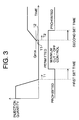
- FIG. 3 is an injection chart based on the control flow diagram.
- FIGS. 4 and 5 are partially expanded view of the injection chart diagram.
- the conventional problem of white smoke generation occurring when a very small quantity of fuel is injected into a cylinder cooled because fuel injection was cut off for the prescribed time is resolved by controlling the fuel injection quantity.
- the fuel injection quantity control device comprises operation means (CPU) 1, memory means (memory: ROM) 2, and detection means (various sensors) 3, and controls the period and quantity of fuel injection by controlling a controller 4 of injectors.
- the CPU 1 comprises injection quantity determination means 5 for determining the required fuel injection quantity Q based on the engine revolution speed (rpm) and accelerator opening degree.
- the injection quantity determination means inputs the engine revolution speed and accelerator opening degree obtained from the various sensors 3 into the prescribed map which is read from the memory 2 and determines the required fuel injection quantity Q.
- the CPU 1 is also provided with control means 6.
- the above-mentioned minute injection quantity Qmin is set to a lower limit injection quantity at which no white smoke is discharged from the diesel engine by taking into account the driving conditions, when fuel is injected into the cylinders cooled by the fuel injection cut-off.
- the CPU 1 also comprises a first timer 7 for measuring the continuation time of the fuel injection cut-off.
- the first timer 7 measures the injection cut-off continuation time T1 by measuring the injection cut-off signal supplied to the injector controller 4.
- the CPU 1 also comprises first inhibiting and permitting means 8.
- the first inhibiting and permitting means 8 inhibits the minimum cut-off control by the control means 6 when the output time T1 of the first timer 7 is less than the prescribed first set time, and permits the minimum cut-off control when the output time is equal to the first set time or longer.
- the first set time is set to a time in which the temperature inside the cylinders is maintained at a temperature level at which no white smoke is discharged from the diesel engine under the present driving conditions, even if the fuel is injected in a quantity less than the prescribed injection quantity Qmin, the temperature being maintained by the combustion preceding the fuel injection cut-off.
- the CPU 1 also comprises a second timer 9 which measures the elapsed time T2 of injection continuation since the restart of fuel injection.
- the second timer 9 measures the elapsed time T2 since the injection restart by measuring the injection continuation signal supplied to the injection controller 4.
- the second timer 9 may be used with the first timer 7.
- the CPU 1 also comprises second inhibiting and permitting means 10.
- the second inhibiting and permitting means 10 continues the minimum cut-off control with control means 6 when output time T2 of the second timer 9 is less than the prescribed second set time, and cancels the minimum cut-off control when the output time is equal to the prescribed second set time or longer.
- the second set time is set to a time in which the temperature inside the cylinders does not rise to the temperature at which no white smoke is discharged from the diesel engine under the present driving conditions when fuel is injected in a quantity less than the prescribed injection quantity Qmin, even under the effect of combustion resulting from the restarted fuel injection.
- the control flow diagram shown in FIG. 2 is implemented by combined operation of the above-described structural components shown in FIG. 1. Injection is conducted according to the injection chart shown in FIGS. 3 through 5 based on this control flow.
- step S1 a continuation time T1 of fuel injection cut-off is acquired by a first timer 7 (see FIG. 3).
- step S2 it is decided whether the injection cut-off continuation time T1 is less than the preset first set time (for example, 5-6 sec).
- the first set time may be automatically varied so as to extend if the water temperature or oil temperature is high and to shorten if the temperature is low.
- step S3 When the injection cut continuation time T1 is less than the first set time, a transition is made to step S3, the minimum cut-off control is prohibited with first prohibiting-permitting means 8, and the usual injection control is conducted in step S4.
- the temperature inside the cylinders is maintained at a level at which no white smoke is discharged from the diesel engine by combustion preceding the fuel injection cut-off.
- the required fuel injection quantity Q determined by the fuel injection determination means 5 based on the opening degree of the accelerator pedal is less than the minute injection quantity Qmin, injection is conducted by this injection quantity Q (usual injection control). Therefore, good drivability can be maintained for the driver (drive controllability), while preventing the white smoke.
- step S5 it is decided whether fuel injection has been made. This is because, in the state in which the accelerator pedal is released, the injection quantity can become zero even under the usual injection control. Further, as described in the previous section, if the fuel has been injected, in step S6, the first timer 7 resets the injection cut-off continuation time T1. This is because the inside of the cylinder is warmed by the combustion resulting from fuel injection. On the other hand, when the fuel injection has not been made under the usual injection control in step S5, the processing flow returns to step S 1, the injection cut continuation time T1 is integrated, and the processing flow proceeds to step S2.
- step S2 when the integrated injection cut-off continuation time T1 has become the first set time or longer, the processing flow proceeds to step S7, and a minimum cut-off control is permitted by the first prohibiting-permitting means 8 (see FIG. 3 and FIG. 4).
- FIG. 3 illustrates the case in which the minimum cut-off control was permitted, with absolutely no injection being made till the first set time was reached, while the first timer 7 has been calculating the injection cut-off continuation time T1.
- FIG. 3 illustrates the case in which the minimum cut-off control was permitted, with absolutely no injection being made till the first set time was reached, while the first timer 7 has been calculating the injection cut-off continuation time T1.
- step S5 illustrates the case in which the minimum cut-off control was permitted, while injection was temporarily made before the first set time was reached, while the first timer 7 has been calculating the injection cut-off continuation time T1 (step S5), the injection cut-off continuation time T1 was reset when this injection was terminated (step S6), and no injection was thereafter made till the first set time was reached.
- step S8 the required fuel injection quantity Q is acquired.
- the required fuel injection quantity Q as described hereinabove, is determined by the injection quantity determination means 5 based on the accelerator opening degree and engine revolution speed. Further, in step S9, it is decided whether the required fuel injection quantity Q is less than the prescribed injection quantity Qmin (for example, 7-8% of the maximum injection quantity.) Furthermore, the minute injection quantity Qmin may be automatically varied so as to increase if the water temperature or oil temperature is high and to decrease if the temperature is low.
- step S 10 fuel injection is cut off, and the preceding fuel injection cut-off is continued.
- This pattern is shown in FIG. 3.
- a broken line 11 represents the required fuel injection quantity Q determined by the injection quantity determination means 5
- a solid line 12 represents the actual injection quantity controlled by the control means 6.
- the injection cut-off is thus continued because if the fuel in a quantity less than the minute injection quantity Qmin is injected, the inside of the cylinders is cooled by the preceding fuel injection cut-off and therefore the entire fuel is not properly combusted and white smoke is generated.
- step S11 step S11 is described below
- the processing flow circulates through steps S8 - S11, and fuel injection is cut-off till the required fuel injection quantity Q becomes the minute injection quantity Qmin or higher.
- step S9 When in step S9, the required fuel injection quantity Q becomes the prescribed injection quantity Qmin or higher, the injection is restarted with the required fuel injection quantity Q in Step 12. If the fuel injection quantity is the minute injection quantity Qmin or higher, the combustion of the injected fuel is successively expanded, the entire fuel is appropriately combusted, and no white smoke is generated even if the inside of the cylinders was cold. Further, in step S13, an elapsed time T2 of injection continuation since the fuel injection was restarted is acquired. The elapsed time is measured in the manner as follows by the second timer 9.
- step S14 it is decided whether the elapsed time T2 is less than the second set time (for example, 5-6 sec) that was set in advance.
- the second set time may be equal to the first set time or different therefrom, and may be automatically varied so as to extend if the water temperature or oil temperature is high and to shorten if the temperature is low.
- the processing flow proceeds to step S15 and permission of the minimum cut-off control with the control means 6 is continued.
- the processing flow then returns to step S8 and circulates through steps S8-S15.
- the second timer 9 resets the elapsed time T2, as shown in FIG. 5. Combustion resulting from fuel injection within the period less than the elapsed time T2 cannot warm the inside of the cylinders to a degree sufficient to contribute to white smoke suppression. For this reason, the elapsed time T2 is measured from the second injection instant.
- the minute injection quantity Qmin(lo) which becomes a threshold value when the quantity of fuel in reduced is set low with respect to the minute injection quantity Qmin(hi) which becomes a threshold value when the injection quantity is increased. Therefore, strictly speaking, the minute injection quantity Qmin shown in FIG. 3 is a minute injection quantity Qmin(hi).
- step S14 When the elapsed time T2 is equal to or longer than the second set time in step S14, the processing flow proceeds to step 16, and the minimum cut-off control conducted by the control means 6 is cancelled (prohibited) (see FIG. 3 and FIG 5). Thus, the minimum cut-off control that was heretofore permitted is prohibited, and in step S17, the usual injection control (control at which, even if the required injection quantity Q is less than the minute injection quantity Qmin, injection conducted at this Q) is conducted. If combustion is continuously conducted for the second set time or longer, the inside of the cylinders is sufficiently heated and no white smoke is produced even if the fuel is injected in a quantity less than the minute injection quantity Q in. Therefore, good drivability (drive controllability) can be guaranteed for the driver, while the white smoke is being prevented.
Landscapes
- Engineering & Computer Science (AREA)
- Chemical & Material Sciences (AREA)
- Combustion & Propulsion (AREA)
- Mechanical Engineering (AREA)
- General Engineering & Computer Science (AREA)
- Electrical Control Of Air Or Fuel Supplied To Internal-Combustion Engine (AREA)
- Output Control And Ontrol Of Special Type Engine (AREA)
Abstract
Description
Claims (6)
- A fuel injection quantity control device for a diesel engine, having injection quantity determination means for determining the required fuel injection quantity based on the accelerator opening degree and engine revolution speed, the device comprising control means for conducting a minimum cut-off control such that at the time the injection is to be restarted after fuel injection has been cut-off for the predetermined time, the fuel injection cut-off is continued when the required injection quantity determined by said injection quantity determination means is less than the prescribed minute injection quantity, and the fuel injection is restarted when the required injection quantity is equal to the prescribed minute injection quantity or larger, this restart being made with the required injection quantity attained at this time.
- A fuel injection quantity control device for a diesel engine according to claim 1, comprising:a first timer for measuring the continuation time of the fuel injection cut-off; andfirst prohibiting and permitting means for prohibiting the minimum cut-off control by said control means when the output time of said first timer is less than the prescribed first set time and permitting the minimum cut-off control by said control means when the output time of said first timer is equal to the first set time or longer.
- A fuel injection quantity control device for a diesel engine according to claim 2, comprising:a second timer for measuring elapsed time since the fuel injection was restarted, when permission of the minimum cut-off control by said control means is continued; andsecond prohibiting and permitting means for continuing permission of the minimum cut-off control by said control means when the output time of said second timer is less than the prescribed second set time and prohibiting the minimum cut-off control by said control means when the output time of said second timer is equal to the second set time or longer.
- The fuel injection quantity control device for a diesel engine according to claim 1 thorough 3, characterized in that said prescribed minute injection quantity is set to a lower limit injection quantity at which no white smoke is discharged from the diesel engine when fuel injection is restarted inside the cylinders.
- The fuel injection quantity control device for a diesel engine according to claim 2 through 4, characterized in that said first set time is set to a time such that due to combustion preceding the fuel injection cut-off, the temperature inside the cylinders is maintained at a temperature at which no white smoke is discharged from the diesel engine even if the fuel is injected in a quantity less than the prescribed minute injection quantity.
- The fuel injection quantity control device for a diesel engine according to claim 3 through 5, characterized in that said second set time is set to a time such that the temperature inside the cylinders does not rise to a temperature at which no white smoke is discharged from the diesel engine when the fuel is injected in a quantity less than the prescribed minute injection quantity, even under the effect of combustion resulting from the restarted fuel injection.
Applications Claiming Priority (2)
| Application Number | Priority Date | Filing Date | Title |
|---|---|---|---|
| JP2002366213A JP4075603B2 (en) | 2002-12-18 | 2002-12-18 | Fuel injection amount control device for diesel engine |
| JP2002366213 | 2002-12-18 |
Publications (3)
| Publication Number | Publication Date |
|---|---|
| EP1431552A2 true EP1431552A2 (en) | 2004-06-23 |
| EP1431552A3 EP1431552A3 (en) | 2005-05-18 |
| EP1431552B1 EP1431552B1 (en) | 2008-04-16 |
Family
ID=32376259
Family Applications (1)
| Application Number | Title | Priority Date | Filing Date |
|---|---|---|---|
| EP03028760A Expired - Lifetime EP1431552B1 (en) | 2002-12-18 | 2003-12-12 | Fuel injection quantity control device for diesel engine |
Country Status (5)
| Country | Link |
|---|---|
| US (1) | US6947825B2 (en) |
| EP (1) | EP1431552B1 (en) |
| JP (1) | JP4075603B2 (en) |
| AT (1) | ATE392544T1 (en) |
| DE (1) | DE60320361T2 (en) |
Families Citing this family (1)
| Publication number | Priority date | Publication date | Assignee | Title |
|---|---|---|---|---|
| JP5210791B2 (en) * | 2008-10-08 | 2013-06-12 | 株式会社日本自動車部品総合研究所 | Fuel injection device |
Family Cites Families (7)
| Publication number | Priority date | Publication date | Assignee | Title |
|---|---|---|---|---|
| US4150651A (en) * | 1977-12-29 | 1979-04-24 | Cummins Engine Company, Inc. | Fuel system for internal combustion engine |
| JPS59141771A (en) * | 1983-02-03 | 1984-08-14 | Nippon Denso Co Ltd | Control device for diesel engine |
| JPH06294327A (en) | 1993-04-08 | 1994-10-21 | Komatsu Ltd | White smoke reducing method and device for diesel engine with supercharger |
| US6092504A (en) * | 1998-08-04 | 2000-07-25 | Caterpillar Inc. | Device for controlling engine speed using dual governors |
| KR100353991B1 (en) * | 1999-12-24 | 2002-09-26 | 현대자동차주식회사 | Method for controlling diesel engine for vehicles |
| JP2002155765A (en) | 2000-11-17 | 2002-05-31 | Mitsubishi Heavy Ind Ltd | White smoke prevention device of diesel engine |
| JP3788736B2 (en) * | 2000-12-18 | 2006-06-21 | スズキ株式会社 | Engine automatic stop / start control device |
-
2002
- 2002-12-18 JP JP2002366213A patent/JP4075603B2/en not_active Expired - Fee Related
-
2003
- 2003-12-12 US US10/734,875 patent/US6947825B2/en not_active Expired - Fee Related
- 2003-12-12 DE DE60320361T patent/DE60320361T2/en not_active Expired - Lifetime
- 2003-12-12 EP EP03028760A patent/EP1431552B1/en not_active Expired - Lifetime
- 2003-12-12 AT AT03028760T patent/ATE392544T1/en not_active IP Right Cessation
Also Published As
| Publication number | Publication date |
|---|---|
| US6947825B2 (en) | 2005-09-20 |
| ATE392544T1 (en) | 2008-05-15 |
| DE60320361D1 (en) | 2008-05-29 |
| DE60320361T2 (en) | 2009-05-07 |
| EP1431552B1 (en) | 2008-04-16 |
| JP2004197633A (en) | 2004-07-15 |
| EP1431552A3 (en) | 2005-05-18 |
| US20040128056A1 (en) | 2004-07-01 |
| JP4075603B2 (en) | 2008-04-16 |
Similar Documents
| Publication | Publication Date | Title |
|---|---|---|
| US8972150B2 (en) | Selective cylinder disablement control systems and methods | |
| US8855896B2 (en) | Intake manifold refill and holding control systems and methods | |
| US8474310B2 (en) | Valve freeze control apparatus and sensor element breakage control apparatus for internal combustion engine | |
| JP2006090308A (en) | Method and apparatus for operating internal combustion engine having catalyst | |
| JP2006207575A (en) | Internal combustion engine and control method thereof | |
| JP2006220026A (en) | Control device for internal combustion engine | |
| JP2008232007A (en) | Start control device for internal combustion engine | |
| JP4099755B2 (en) | Start control device for internal combustion engine | |
| US6598588B2 (en) | Controlling of ignition timing of an internal combustion engine | |
| JPH07253041A (en) | Fuel injection control device | |
| JP4453584B2 (en) | Control device for internal combustion engine | |
| EP1431552B1 (en) | Fuel injection quantity control device for diesel engine | |
| JP2006183493A (en) | Control device for internal combustion engine | |
| JP2005155462A (en) | Start control device for internal combustion engine | |
| JP4389680B2 (en) | Ignition control device for internal combustion engine | |
| JP7555677B2 (en) | Control device for internal combustion engine | |
| JPH0734929A (en) | Engine fuel controller | |
| JPH06307270A (en) | Starting fuel injection controller for internal combustion engine | |
| JPH0615829B2 (en) | Electronically controlled fuel injection device for internal combustion engine | |
| KR100521186B1 (en) | Diesel oiling preventing method of diesel engine vehicle | |
| JP6736207B2 (en) | Control device for internal combustion engine | |
| JP4477561B2 (en) | Control device for internal combustion engine | |
| JP2025034605A (en) | Fuel supply device control device | |
| JP3630034B2 (en) | Engine start control device | |
| JPS6013945A (en) | Method of increasing fuel after starting of electronically controlled fuel injection type engine |
Legal Events
| Date | Code | Title | Description |
|---|---|---|---|
| PUAI | Public reference made under article 153(3) epc to a published international application that has entered the european phase |
Free format text: ORIGINAL CODE: 0009012 |
|
| AK | Designated contracting states |
Kind code of ref document: A2 Designated state(s): AT BE BG CH CY CZ DE DK EE ES FI FR GB GR HU IE IT LI LU MC NL PT RO SE SI SK TR |
|
| AX | Request for extension of the european patent |
Extension state: AL LT LV MK |
|
| PUAL | Search report despatched |
Free format text: ORIGINAL CODE: 0009013 |
|
| AK | Designated contracting states |
Kind code of ref document: A3 Designated state(s): AT BE BG CH CY CZ DE DK EE ES FI FR GB GR HU IE IT LI LU MC NL PT RO SE SI SK TR |
|
| AX | Request for extension of the european patent |
Extension state: AL LT LV MK |
|
| 17P | Request for examination filed |
Effective date: 20051109 |
|
| AKX | Designation fees paid |
Designated state(s): AT BE BG CH CY CZ DE DK EE ES FI FR GB GR HU IE IT LI LU MC NL PT RO SE SI SK TR |
|
| GRAP | Despatch of communication of intention to grant a patent |
Free format text: ORIGINAL CODE: EPIDOSNIGR1 |
|
| GRAS | Grant fee paid |
Free format text: ORIGINAL CODE: EPIDOSNIGR3 |
|
| GRAA | (expected) grant |
Free format text: ORIGINAL CODE: 0009210 |
|
| AK | Designated contracting states |
Kind code of ref document: B1 Designated state(s): AT BE BG CH CY CZ DE DK EE ES FI FR GB GR HU IE IT LI LU MC NL PT RO SE SI SK TR |
|
| REG | Reference to a national code |
Ref country code: CH Ref legal event code: EP |
|
| REG | Reference to a national code |
Ref country code: IE Ref legal event code: FG4D |
|
| REF | Corresponds to: |
Ref document number: 60320361 Country of ref document: DE Date of ref document: 20080529 Kind code of ref document: P |
|
| PG25 | Lapsed in a contracting state [announced via postgrant information from national office to epo] |
Ref country code: SI Free format text: LAPSE BECAUSE OF FAILURE TO SUBMIT A TRANSLATION OF THE DESCRIPTION OR TO PAY THE FEE WITHIN THE PRESCRIBED TIME-LIMIT Effective date: 20080416 |
|
| NLV1 | Nl: lapsed or annulled due to failure to fulfill the requirements of art. 29p and 29m of the patents act | ||
| PG25 | Lapsed in a contracting state [announced via postgrant information from national office to epo] |
Ref country code: FI Free format text: LAPSE BECAUSE OF FAILURE TO SUBMIT A TRANSLATION OF THE DESCRIPTION OR TO PAY THE FEE WITHIN THE PRESCRIBED TIME-LIMIT Effective date: 20080416 Ref country code: ES Free format text: LAPSE BECAUSE OF FAILURE TO SUBMIT A TRANSLATION OF THE DESCRIPTION OR TO PAY THE FEE WITHIN THE PRESCRIBED TIME-LIMIT Effective date: 20080727 Ref country code: BG Free format text: LAPSE BECAUSE OF FAILURE TO SUBMIT A TRANSLATION OF THE DESCRIPTION OR TO PAY THE FEE WITHIN THE PRESCRIBED TIME-LIMIT Effective date: 20080716 Ref country code: PT Free format text: LAPSE BECAUSE OF FAILURE TO SUBMIT A TRANSLATION OF THE DESCRIPTION OR TO PAY THE FEE WITHIN THE PRESCRIBED TIME-LIMIT Effective date: 20080916 Ref country code: NL Free format text: LAPSE BECAUSE OF FAILURE TO SUBMIT A TRANSLATION OF THE DESCRIPTION OR TO PAY THE FEE WITHIN THE PRESCRIBED TIME-LIMIT Effective date: 20080416 |
|
| PG25 | Lapsed in a contracting state [announced via postgrant information from national office to epo] |
Ref country code: AT Free format text: LAPSE BECAUSE OF FAILURE TO SUBMIT A TRANSLATION OF THE DESCRIPTION OR TO PAY THE FEE WITHIN THE PRESCRIBED TIME-LIMIT Effective date: 20080416 |
|
| ET | Fr: translation filed | ||
| PG25 | Lapsed in a contracting state [announced via postgrant information from national office to epo] |
Ref country code: DK Free format text: LAPSE BECAUSE OF FAILURE TO SUBMIT A TRANSLATION OF THE DESCRIPTION OR TO PAY THE FEE WITHIN THE PRESCRIBED TIME-LIMIT Effective date: 20080416 Ref country code: SE Free format text: LAPSE BECAUSE OF FAILURE TO SUBMIT A TRANSLATION OF THE DESCRIPTION OR TO PAY THE FEE WITHIN THE PRESCRIBED TIME-LIMIT Effective date: 20080716 Ref country code: CZ Free format text: LAPSE BECAUSE OF FAILURE TO SUBMIT A TRANSLATION OF THE DESCRIPTION OR TO PAY THE FEE WITHIN THE PRESCRIBED TIME-LIMIT Effective date: 20080416 |
|
| PLBE | No opposition filed within time limit |
Free format text: ORIGINAL CODE: 0009261 |
|
| STAA | Information on the status of an ep patent application or granted ep patent |
Free format text: STATUS: NO OPPOSITION FILED WITHIN TIME LIMIT |
|
| PG25 | Lapsed in a contracting state [announced via postgrant information from national office to epo] |
Ref country code: BE Free format text: LAPSE BECAUSE OF FAILURE TO SUBMIT A TRANSLATION OF THE DESCRIPTION OR TO PAY THE FEE WITHIN THE PRESCRIBED TIME-LIMIT Effective date: 20080416 Ref country code: SK Free format text: LAPSE BECAUSE OF FAILURE TO SUBMIT A TRANSLATION OF THE DESCRIPTION OR TO PAY THE FEE WITHIN THE PRESCRIBED TIME-LIMIT Effective date: 20080416 Ref country code: RO Free format text: LAPSE BECAUSE OF FAILURE TO SUBMIT A TRANSLATION OF THE DESCRIPTION OR TO PAY THE FEE WITHIN THE PRESCRIBED TIME-LIMIT Effective date: 20080416 |
|
| 26N | No opposition filed |
Effective date: 20090119 |
|
| PG25 | Lapsed in a contracting state [announced via postgrant information from national office to epo] |
Ref country code: EE Free format text: LAPSE BECAUSE OF FAILURE TO SUBMIT A TRANSLATION OF THE DESCRIPTION OR TO PAY THE FEE WITHIN THE PRESCRIBED TIME-LIMIT Effective date: 20080416 |
|
| PG25 | Lapsed in a contracting state [announced via postgrant information from national office to epo] |
Ref country code: MC Free format text: LAPSE BECAUSE OF NON-PAYMENT OF DUE FEES Effective date: 20081231 |
|
| REG | Reference to a national code |
Ref country code: CH Ref legal event code: PL |
|
| PG25 | Lapsed in a contracting state [announced via postgrant information from national office to epo] |
Ref country code: IT Free format text: LAPSE BECAUSE OF FAILURE TO SUBMIT A TRANSLATION OF THE DESCRIPTION OR TO PAY THE FEE WITHIN THE PRESCRIBED TIME-LIMIT Effective date: 20080416 |
|
| PG25 | Lapsed in a contracting state [announced via postgrant information from national office to epo] |
Ref country code: CY Free format text: LAPSE BECAUSE OF FAILURE TO SUBMIT A TRANSLATION OF THE DESCRIPTION OR TO PAY THE FEE WITHIN THE PRESCRIBED TIME-LIMIT Effective date: 20080416 |
|
| PG25 | Lapsed in a contracting state [announced via postgrant information from national office to epo] |
Ref country code: IE Free format text: LAPSE BECAUSE OF NON-PAYMENT OF DUE FEES Effective date: 20081212 Ref country code: LI Free format text: LAPSE BECAUSE OF NON-PAYMENT OF DUE FEES Effective date: 20081231 Ref country code: CH Free format text: LAPSE BECAUSE OF NON-PAYMENT OF DUE FEES Effective date: 20081231 |
|
| PG25 | Lapsed in a contracting state [announced via postgrant information from national office to epo] |
Ref country code: LU Free format text: LAPSE BECAUSE OF NON-PAYMENT OF DUE FEES Effective date: 20081212 Ref country code: HU Free format text: LAPSE BECAUSE OF FAILURE TO SUBMIT A TRANSLATION OF THE DESCRIPTION OR TO PAY THE FEE WITHIN THE PRESCRIBED TIME-LIMIT Effective date: 20081017 |
|
| PG25 | Lapsed in a contracting state [announced via postgrant information from national office to epo] |
Ref country code: TR Free format text: LAPSE BECAUSE OF FAILURE TO SUBMIT A TRANSLATION OF THE DESCRIPTION OR TO PAY THE FEE WITHIN THE PRESCRIBED TIME-LIMIT Effective date: 20080416 |
|
| PG25 | Lapsed in a contracting state [announced via postgrant information from national office to epo] |
Ref country code: GR Free format text: LAPSE BECAUSE OF FAILURE TO SUBMIT A TRANSLATION OF THE DESCRIPTION OR TO PAY THE FEE WITHIN THE PRESCRIBED TIME-LIMIT Effective date: 20080717 |
|
| PGFP | Annual fee paid to national office [announced via postgrant information from national office to epo] |
Ref country code: FR Payment date: 20130107 Year of fee payment: 10 |
|
| REG | Reference to a national code |
Ref country code: FR Ref legal event code: ST Effective date: 20140829 |
|
| PG25 | Lapsed in a contracting state [announced via postgrant information from national office to epo] |
Ref country code: FR Free format text: LAPSE BECAUSE OF NON-PAYMENT OF DUE FEES Effective date: 20131231 |
|
| REG | Reference to a national code |
Ref country code: DE Ref legal event code: R082 Ref document number: 60320361 Country of ref document: DE Representative=s name: SCHAUMBURG UND PARTNER PATENTANWAELTE MBB, DE Ref country code: DE Ref legal event code: R082 Ref document number: 60320361 Country of ref document: DE Representative=s name: SCHAUMBURG & PARTNER PATENTANWAELTE GBR, DE Ref country code: DE Ref legal event code: R082 Ref document number: 60320361 Country of ref document: DE Representative=s name: SCHAUMBURG & PARTNER PATENTANWAELTE MBB, DE |
|
| PGFP | Annual fee paid to national office [announced via postgrant information from national office to epo] |
Ref country code: DE Payment date: 20151208 Year of fee payment: 13 Ref country code: GB Payment date: 20151209 Year of fee payment: 13 |
|
| REG | Reference to a national code |
Ref country code: DE Ref legal event code: R119 Ref document number: 60320361 Country of ref document: DE |
|
| GBPC | Gb: european patent ceased through non-payment of renewal fee |
Effective date: 20161212 |
|
| PG25 | Lapsed in a contracting state [announced via postgrant information from national office to epo] |
Ref country code: DE Free format text: LAPSE BECAUSE OF NON-PAYMENT OF DUE FEES Effective date: 20170701 Ref country code: GB Free format text: LAPSE BECAUSE OF NON-PAYMENT OF DUE FEES Effective date: 20161212 |