EP1431516A2 - Ensemble diffuseur - Google Patents
Ensemble diffuseur Download PDFInfo
- Publication number
- EP1431516A2 EP1431516A2 EP03257218A EP03257218A EP1431516A2 EP 1431516 A2 EP1431516 A2 EP 1431516A2 EP 03257218 A EP03257218 A EP 03257218A EP 03257218 A EP03257218 A EP 03257218A EP 1431516 A2 EP1431516 A2 EP 1431516A2
- Authority
- EP
- European Patent Office
- Prior art keywords
- arrangement
- aperture
- conduit
- wall surface
- flow
- Prior art date
- Legal status (The legal status is an assumption and is not a legal conclusion. Google has not performed a legal analysis and makes no representation as to the accuracy of the status listed.)
- Granted
Links
- 239000012530 fluid Substances 0.000 claims abstract description 21
- 238000011144 upstream manufacturing Methods 0.000 claims abstract description 18
- 238000006073 displacement reaction Methods 0.000 claims abstract description 12
- 238000001816 cooling Methods 0.000 claims description 7
- 230000004888 barrier function Effects 0.000 claims description 4
- 230000001419 dependent effect Effects 0.000 claims description 3
- 238000004519 manufacturing process Methods 0.000 abstract description 3
- 238000007493 shaping process Methods 0.000 abstract description 3
- 238000010348 incorporation Methods 0.000 abstract description 2
- 235000013290 Sagittaria latifolia Nutrition 0.000 description 9
- 235000015246 common arrowhead Nutrition 0.000 description 9
- 238000009792 diffusion process Methods 0.000 description 8
- 238000002485 combustion reaction Methods 0.000 description 6
- 238000000926 separation method Methods 0.000 description 5
- 238000009434 installation Methods 0.000 description 4
- 230000000740 bleeding effect Effects 0.000 description 3
- 230000009471 action Effects 0.000 description 2
- 230000008859 change Effects 0.000 description 2
- 238000003776 cleavage reaction Methods 0.000 description 2
- 239000002826 coolant Substances 0.000 description 2
- 230000007017 scission Effects 0.000 description 2
- 230000003068 static effect Effects 0.000 description 2
- 230000002301 combined effect Effects 0.000 description 1
- 238000010276 construction Methods 0.000 description 1
- 230000000694 effects Effects 0.000 description 1
- 230000007246 mechanism Effects 0.000 description 1
- 230000000750 progressive effect Effects 0.000 description 1
- 238000011084 recovery Methods 0.000 description 1
- 230000009467 reduction Effects 0.000 description 1
- 238000009877 rendering Methods 0.000 description 1
- 230000000717 retained effect Effects 0.000 description 1
Images

Classifications
-
- F—MECHANICAL ENGINEERING; LIGHTING; HEATING; WEAPONS; BLASTING
- F01—MACHINES OR ENGINES IN GENERAL; ENGINE PLANTS IN GENERAL; STEAM ENGINES
- F01D—NON-POSITIVE DISPLACEMENT MACHINES OR ENGINES, e.g. STEAM TURBINES
- F01D9/00—Stators
- F01D9/02—Nozzles; Nozzle boxes; Stator blades; Guide conduits, e.g. individual nozzles
- F01D9/04—Nozzles; Nozzle boxes; Stator blades; Guide conduits, e.g. individual nozzles forming ring or sector
Definitions
- the present invention relates to diffuser arrangements and more particularly to diffuser arrangements used within gas turbine engines which utilise bleed in order to increase area ratios and divergence angles within a given length and that the bleed air can then be utilised for component cooling.
- a compressor stage presents an airflow to a combustion chamber where high temperatures and gas flows allow a turbine system to drive the engine.
- a diffuser arrangement is provided in order to reduce airflow velocity and increase static pressure.
- air is diffused or bled from the output compressor air flow. This diffused air is utilised for cooling and other purposes about the engine.
- a diffuser arrangement for an engine comprising a wall surface in a fluid flow conduit and formed with an aperture between an upstream part of the wall surface and a downstream part of the wall surface, the downstream part having a step displacement away from a projected profile of the upstream part of the wall surface whereby in use flow momentum in a fluid flow past the wall surface facilitates flow bleed into the aperture.
- the fluid flow is air flow from a compressor.
- the upstream part has a leading edge to the aperture shaped to enhance flow momentum thereabout towards the aperture.
- the edge is curved into the aperture.
- the edge has a curvature dependent upon expected flow rate and/or cross-section of the conduit including the wall surface.
- the curvature will have a radius in the order of 0.05 to 0.15 and preferably 0.09 to 0.11 of an inlet passage height h, to the conduit.
- the downstream part has a trailing edge to the aperture which is angularly presented.
- the down steam part will be at an angle in the order of 20 to 40° to the principal axis of fluid flow, preferably the angle is 30°.
- the step displacement of the downstream part relative to the upstream part is in the order of 0.05 to 0.12 and preferably 0.06 to 0.1 of the inlet passage height, h.
- the aperture is divergent away from an opening in the wall surface.
- the aperture has a width at the opening in the wall surface in the order of 0.04 to 0.07 and preferably 0.05 to 0.06 of the inlet passage height.
- the aperture will have an aperture wall upon the side towards the downstream part which is substantially perpendicular to the principal axis of the fluid flow.
- the combined length of the wall surface will be three to four times the inlet passage height.
- downstream part will be shaped to create a gate or barrier.
- the aperture will be coupled to a cooling system for an engine in order to provide fluid as a coolant flow for that engine.
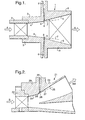
- the diffuser arrangement 1 includes an inlet 2 which presents a fluid or air flow in the direction of arrow head A to the diffuser arrangement 1.
- the arrangement incorporates wall surfaces 3 which in turn comprise an upstream part 4 and a downstream part 5 divided by an aperture 6 between these parts 4, 5.
- the fluid air flow in the direction of arrow head A passes through the inlet 2 and out of the arrangement 1 with a proportion of that fluid air flow bled or diffused through the aperture 6.
- This diffused or bled air taken through the aperture 6 is utilised for cooling etc in other parts of the engine.
- the upstream parts 4 are presented such that a projected profile depicted by broken lines 7 which is a continuation of the upstream part 4 surface is not consistent with the extending surface of the downstream parts 5.
- the downstream parts 5 present a surface which is step displaced from that projected profile 7 such that a transfer of momentum from the air flow to the aperture reduces boundary layer development and prevents air flow separation within the diffuser arrangement 1.
- the specific shaping of the aperture 6, the degree of step displacement between the projected profile 7 and the downstream part 5 surface and the width of the opening to the aperture 6 are all highly determinant of performance. In such circumstances, an analysis of the overall fluid air flow within the diffuser arrangement 1 for a particular installation is required in order to determine the necessary specific factors for that installation. Detail of the specific considerations will be outlined later.
- leading edge 8 of the aperture 6 will be generally shaped and in particular rounded in order to create increased momentum flow directed towards the aperture 6 whilst the trailing edge 9 will generally be angularly shaped for more specific cleaving of the air flow between that directed into the aperture 6 and that allowed to continue flowing through the diffuser arrangement 1.
- Fig. 2 illustrates an alternative schematic diffuser arrangement in accordance with the present invention.
- an inlet 22 is again provided through which an air flow in the direction of arrow head B is provided to the arrangement 21.
- this air flow in the direction of arrow head B is split so that only a proportion passes in the conduit 20 in the direction of arrow head BB.
- air is bled through aperture 26 formed in wall surface 23 having an upstream part 24 and a downstream part 25.
- the downstream part 25 is presented in a step displacement from a projected profile 27 taken from the upstream part 24.
- the edge 28 of the aperture 26 is shaped to facilitate the bleed flow into the aperture 26.
- a trailing edge 29 is also again angularly presented to create a wedge for more precise cleavage in the air flow.
- Fig. 3 illustrates a number of the dimensional relationships of a diffuser arrangement 1, 21 in accordance with the present invention. Values for the integers recited in Fig. 3 are provided below in table A. For the avoidance of doubt, it should be appreciated that these dimensional parameters are given for example only and relate to a desired bleed rate of approximately 2.5% of the fluid air flow volume per unit time. Clearly, different installations will require different dimensions within the general teaching of the present description.
- This invention provides a way of increasing pre-diffuser area ratio and/or flow deflection whilst maintaining an attached flow regime. This is achieved under the action of bleeds with the bleed air then utilised for component cooling.
- the flow diffuses and decelerates losing dynamic pressure which is recovered as static pressure.
- the diffuser arrangement can be easily incorporated within an engine without complicated fabrication or constructional difficulties. It will be understood that the present diffuser arrangement comprises an appropriately shaped aperture within a conduit wall surface and so does not require provision of relatively complicated barrier gates or vortex chambers in order to achieve the desired air flow bleeding. Nevertheless, relational considerations are required in order to achieve sufficient performance with the aperture. In particular, the leading edge and the step displacement along with the width of the opening to the aperture will generally be critical in order to achieve the desired diffusion performance.
- Fig. 3 and Table A provide illustrative example ranges and relationships.
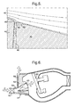
- Figs. 4 and 5 graphically illustrate fluid air flow about an aperture 46.
- an upstream part 45 includes a leading edge 48 which presents an air flow shown by streamlines 40 to the aperture 46.
- a downstream part 45 is presented on the other side of the aperture 46 with an angular trailing edge 49.
- a mechanism is set up by which positive streamwise momentum is transferred from the accelerating bleed flow to the diffusing/decelerating mainstream flow preventing flow separation on the highly aerodynamically loaded edge 48 of part 45.
- the objective is to maintain attached flow throughout the diffuser arrangement.
- the isometric spacing of the streamlines is substantially retained through the expansion of the diffuser arrangement.
- the trailing edge 49 is substantially angular in order to achieve a more clear cut cleavage in the air flow depicted by arrow lines 40.
- the leading edge 48 of the aperture 46 is substantially curved.
- the bleed flow accelerates into the bleed duct 46 over the curved edge 48.
- the profile of the curve prevents flow separation from edge 48.
- a free shear layer between the accelerating bleed flow and diffusing mainstream flow facilitates a transfer of streamwise momentum from the bleed flow to the mainstream flow thus preventing separation.
- the aperture 46 in itself has walls which diverge and so create a slight pressure recovery. This is done to improve the quality of the bleed air making it more suitable for cooling purposes.
- the present invention provides a localised feature about the aperture 46 between the leading edge 48 and the trailing edge 49 which incorporates the combined effects of a step change or displacement in the wall surface formed by those parts 44, 45 as part of the conduit along with preferably a specifically shaped leading edge 48 to enhance flow momentum into the aperture 46.
- a step change or displacement in the wall surface formed by those parts 44, 45 as part of the conduit along with preferably a specifically shaped leading edge 48 to enhance flow momentum into the aperture 46.
- Fig. 6 illustrates a diffuser arrangement 61 in accordance with the present invention associated with a combustor 60.
- the diffuser arrangement 61 is located to receive an air flow in the direction of arrow head C through an inlet 62 the diffuser arrangement 61 incorporates an aperture 66 between an upstream part 64 and a downstream part 65 of a wall surface 63 which in turn is part of a conduit directing the air flow in the direction of arrow head C towards the combustor 60.
- the aperture 66 as described previously draws or bleeds air from the air flow in the direction of arrow head C by a combination of a step displacement change in the wall surface 63 between the upstream part 64 and the downstream part 65 as well as providing a leading edge to that aperture 66 which facilitates diversion of air flow into the aperture 66.
- This air flow in the direction of arrow head D will generally be utilised for coolant about the combustor 60 or other parts of an engine incorporating the combustor 60. More than one diffuser arrangement in accordance with the present invention can be provided for each conduit of air flow towards a combustor or otherwise within an engine.
- a principal objective of the present invention is to provide a diffuser arrangement which is more easily incorporated within an engine without requiring complex fabrication or construction.
- the present aperture may be associated with a flap or other device whereby diffuser arrangements in accordance with the present invention can be brought into and out of operation as required by engine performance.
Applications Claiming Priority (2)
| Application Number | Priority Date | Filing Date | Title |
|---|---|---|---|
| GBGB0229307.4A GB0229307D0 (en) | 2002-12-17 | 2002-12-17 | A diffuser arrangement |
| GB0229307 | 2002-12-17 |
Publications (3)
| Publication Number | Publication Date |
|---|---|
| EP1431516A2 true EP1431516A2 (fr) | 2004-06-23 |
| EP1431516A3 EP1431516A3 (fr) | 2005-03-30 |
| EP1431516B1 EP1431516B1 (fr) | 2009-11-11 |
Family
ID=9949780
Family Applications (1)
| Application Number | Title | Priority Date | Filing Date |
|---|---|---|---|
| EP03257218A Expired - Fee Related EP1431516B1 (fr) | 2002-12-17 | 2003-11-15 | Ensemble diffuseur |
Country Status (4)
| Country | Link |
|---|---|
| US (1) | US7062918B2 (fr) |
| EP (1) | EP1431516B1 (fr) |
| DE (1) | DE60329967D1 (fr) |
| GB (1) | GB0229307D0 (fr) |
Cited By (4)
| Publication number | Priority date | Publication date | Assignee | Title |
|---|---|---|---|---|
| FR2887924A1 (fr) * | 2005-06-30 | 2007-01-05 | Snecma | Dispositif de guidage d'un flux d'air entre un compresseur et une chambre de combustion dans une turbomachine |
| FR2901574A1 (fr) * | 2006-05-29 | 2007-11-30 | Snecma Sa | Dispositif de guidage d'un flux d'air a l'entree d'une chambre de combustion dans une turbomachine |
| WO2013016177A1 (fr) * | 2011-07-22 | 2013-01-31 | The Board Of Trustees Of The Leland Stanford Junior University | Diffuseur possédant un décrochement faisant face vers l'arrière et à hauteur de décrochement variable |
| EP2703604A1 (fr) * | 2012-08-30 | 2014-03-05 | Rolls-Royce Deutschland Ltd & Co KG | Module d'une turbomachine axiale et procédé de fabrication d'un tel module |
Families Citing this family (16)
| Publication number | Priority date | Publication date | Assignee | Title |
|---|---|---|---|---|
| EP1508680A1 (fr) * | 2003-08-18 | 2005-02-23 | Siemens Aktiengesellschaft | Diffuseur situé entre le compresseur et la chambre de combustion d'une turbine à gaz |
| US20110176917A1 (en) * | 2004-07-02 | 2011-07-21 | Brian Haller | Exhaust Gas Diffuser Wall Contouring |
| GB2415749B (en) * | 2004-07-02 | 2009-10-07 | Demag Delaval Ind Turbomachine | A gas turbine engine including an exhaust duct comprising a diffuser for diffusing the exhaust gas produced by the engine |
| FR2880391A1 (fr) * | 2005-01-06 | 2006-07-07 | Snecma Moteurs Sa | Diffuseur pour chambre annulaire de combustion, en particulier pour un turbomoteur d'avion |
| US8162605B2 (en) * | 2008-01-14 | 2012-04-24 | United Technologies Corporation | Gas turbine engine case |
| US8474266B2 (en) * | 2009-07-24 | 2013-07-02 | General Electric Company | System and method for a gas turbine combustor having a bleed duct from a diffuser to a fuel nozzle |
| US8381532B2 (en) * | 2010-01-27 | 2013-02-26 | General Electric Company | Bled diffuser fed secondary combustion system for gas turbines |
| US8418463B2 (en) | 2010-04-15 | 2013-04-16 | Ford Global Technologies, Llc | Condensate management for motor-vehicle compressed air storage systems |
| US8371276B2 (en) | 2010-04-15 | 2013-02-12 | Ford Global Technologies, Llc | Stored compressed air management and flow control for improved engine performance |
| US8069665B2 (en) | 2010-04-15 | 2011-12-06 | Ford Global Technologies, Llc | Stored compressed air management for improved engine performance |
| US8752475B2 (en) | 2010-10-26 | 2014-06-17 | Ford Global Technologies, Llc | Method and system for improving vehicle braking |
| WO2014134529A1 (fr) | 2013-02-28 | 2014-09-04 | United Technologies Corporation | Procédé et appareil de gestion de flux d'air de prédiffusion destiné à refroidir des éléments de turbine haute pression |
| EP2971968A1 (fr) | 2013-03-14 | 2016-01-20 | Rolls-Royce Corporation | Diffuseur à multiples passages avec couche limite réactivée |
| US10612469B2 (en) | 2013-08-05 | 2020-04-07 | United Technologies Corporation | Diffuser case mixing chamber for a turbine engine |
| WO2015031796A1 (fr) | 2013-08-29 | 2015-03-05 | United Technologies Corporation | Carter de diffuseur hybride pour chambre de combustion de moteur à turbine à gaz |
| US11486262B2 (en) * | 2021-03-03 | 2022-11-01 | General Electric Company | Diffuser bleed assembly |
Citations (9)
| Publication number | Priority date | Publication date | Assignee | Title |
|---|---|---|---|---|
| US4098073A (en) | 1976-03-24 | 1978-07-04 | Rolls-Royce Limited | Fluid flow diffuser |
| JPS56162300A (en) | 1980-05-16 | 1981-12-14 | Hitachi Ltd | Manufacture of casing for gas-turbine compressor |
| GB2122690A (en) | 1982-07-01 | 1984-01-18 | Skoda Kp | Steam turbine bleeding slot |
| US4796429A (en) | 1976-11-15 | 1989-01-10 | General Motors Corporation | Combustor diffuser |
| EP0306279A1 (fr) | 1987-09-01 | 1989-03-08 | LUCAS INDUSTRIES public limited company | Maître-cylindre |
| CA2199875A1 (fr) | 1994-10-06 | 1996-04-18 | William E. Carscallen | Purgeur et diffuseur annulaire combines pour conduite intercompresseur de turbine a gaz |
| US5632141A (en) | 1994-09-09 | 1997-05-27 | United Technologies Corporation | Diffuser with controlled diffused air discharge |
| EP1074792A1 (fr) | 1999-07-31 | 2001-02-07 | Rolls-Royce Plc | Agencement de chambre de combustion de turbine |
| JP2001055904A (ja) | 1999-08-17 | 2001-02-27 | Toshiba Corp | 蒸気タービンのドレン分離構造 |
Family Cites Families (7)
| Publication number | Priority date | Publication date | Assignee | Title |
|---|---|---|---|---|
| US3011307A (en) * | 1955-12-15 | 1961-12-05 | Gen Electric | Variable throat supersonic diffuser |
| US3216455A (en) * | 1961-12-05 | 1965-11-09 | Gen Electric | High performance fluidynamic component |
| DE3168712D1 (de) * | 1980-03-10 | 1985-03-21 | Rolls Royce | Diffusion apparatus |
| RO82608A (fr) * | 1981-01-08 | 1983-09-26 | Societe Anonyme Dite Alsthom-Atlantique,Fr | Diffuseur avec aspiration parietale |
| US6048171A (en) | 1997-09-09 | 2000-04-11 | United Technologies Corporation | Bleed valve system |
| US6092987A (en) * | 1998-02-27 | 2000-07-25 | United Technologies Corporation | Stator assembly for a rotary machine |
| US6325595B1 (en) | 2000-03-24 | 2001-12-04 | General Electric Company | High recovery multi-use bleed |
-
2002
- 2002-12-17 GB GBGB0229307.4A patent/GB0229307D0/en not_active Ceased
-
2003
- 2003-11-15 EP EP03257218A patent/EP1431516B1/fr not_active Expired - Fee Related
- 2003-11-15 DE DE60329967T patent/DE60329967D1/de not_active Expired - Lifetime
- 2003-12-02 US US10/724,628 patent/US7062918B2/en not_active Expired - Fee Related
Patent Citations (9)
| Publication number | Priority date | Publication date | Assignee | Title |
|---|---|---|---|---|
| US4098073A (en) | 1976-03-24 | 1978-07-04 | Rolls-Royce Limited | Fluid flow diffuser |
| US4796429A (en) | 1976-11-15 | 1989-01-10 | General Motors Corporation | Combustor diffuser |
| JPS56162300A (en) | 1980-05-16 | 1981-12-14 | Hitachi Ltd | Manufacture of casing for gas-turbine compressor |
| GB2122690A (en) | 1982-07-01 | 1984-01-18 | Skoda Kp | Steam turbine bleeding slot |
| EP0306279A1 (fr) | 1987-09-01 | 1989-03-08 | LUCAS INDUSTRIES public limited company | Maître-cylindre |
| US5632141A (en) | 1994-09-09 | 1997-05-27 | United Technologies Corporation | Diffuser with controlled diffused air discharge |
| CA2199875A1 (fr) | 1994-10-06 | 1996-04-18 | William E. Carscallen | Purgeur et diffuseur annulaire combines pour conduite intercompresseur de turbine a gaz |
| EP1074792A1 (fr) | 1999-07-31 | 2001-02-07 | Rolls-Royce Plc | Agencement de chambre de combustion de turbine |
| JP2001055904A (ja) | 1999-08-17 | 2001-02-27 | Toshiba Corp | 蒸気タービンのドレン分離構造 |
Cited By (8)
| Publication number | Priority date | Publication date | Assignee | Title |
|---|---|---|---|---|
| FR2887924A1 (fr) * | 2005-06-30 | 2007-01-05 | Snecma | Dispositif de guidage d'un flux d'air entre un compresseur et une chambre de combustion dans une turbomachine |
| FR2901574A1 (fr) * | 2006-05-29 | 2007-11-30 | Snecma Sa | Dispositif de guidage d'un flux d'air a l'entree d'une chambre de combustion dans une turbomachine |
| EP1862644A1 (fr) * | 2006-05-29 | 2007-12-05 | Snecma | Dispositif de guidage d'un flux d'air à l'entrée d'une chambre de combustion dans une turbomachine |
| US7862295B2 (en) | 2006-05-29 | 2011-01-04 | Snecma | Device for guiding a stream of air entering a combustion chamber of a turbomachine |
| WO2013016177A1 (fr) * | 2011-07-22 | 2013-01-31 | The Board Of Trustees Of The Leland Stanford Junior University | Diffuseur possédant un décrochement faisant face vers l'arrière et à hauteur de décrochement variable |
| US9109466B2 (en) | 2011-07-22 | 2015-08-18 | The Board Of Trustees Of The Leland Stanford Junior University | Diffuser with backward facing step having varying step height |
| EP2703604A1 (fr) * | 2012-08-30 | 2014-03-05 | Rolls-Royce Deutschland Ltd & Co KG | Module d'une turbomachine axiale et procédé de fabrication d'un tel module |
| US9366148B2 (en) | 2012-08-30 | 2016-06-14 | Rolls-Royce Deutschland Ltd & Co Kg | Assembly of an axial turbomachine and method for manufacturing an assembly of this type |
Also Published As
| Publication number | Publication date |
|---|---|
| US7062918B2 (en) | 2006-06-20 |
| DE60329967D1 (de) | 2009-12-24 |
| US20040244379A1 (en) | 2004-12-09 |
| EP1431516A3 (fr) | 2005-03-30 |
| GB0229307D0 (en) | 2003-01-22 |
| EP1431516B1 (fr) | 2009-11-11 |
Similar Documents
| Publication | Publication Date | Title |
|---|---|---|
| US7062918B2 (en) | Diffuser arrangement | |
| US11215196B2 (en) | Diffuser pipe with splitter vane | |
| EP2660424B1 (fr) | Conduits inter-turbine avec rapports de surfaces variables | |
| RU2711204C2 (ru) | Узел спрямления воздушного потока газотурбинного двигателя и газотурбинный двигатель, содержащий такой узел | |
| US20100199633A1 (en) | Bleed structure for a bleed passage in a gas turbine engine | |
| EP2071155A2 (fr) | Ensemble formant nacelle ayant des turbulateurs | |
| EP2239428A2 (fr) | Plénum d'échappement pour moteur à turbine | |
| GB1573926A (en) | Fluid flow diffuser | |
| US20100180574A1 (en) | Gas turbine engine | |
| US9885371B2 (en) | Row of aerofoil members | |
| EP3483395B1 (fr) | Conduits inter-turbine comportant des mécanismes de régulation d'écoulement | |
| Cheng et al. | Effect of tip clearance variation in the transonic axial compressor of a miniature gas turbine at different Reynolds numbers | |
| EP2157281B1 (fr) | Aube de turbine à gaz avec refroidissement par impact | |
| Tamaki et al. | Aerodynamic design to increase pressure ratio of centrifugal compressors for turbochargers | |
| US20050232770A1 (en) | Flow control arrangement | |
| Ishida et al. | Effect of pre-whirl on unstable flow suppression in a centrifugal impeller with ring groove arrangement | |
| JPH10238307A (ja) | 軸流タービン | |
| US20100064656A1 (en) | Engines and methods of operating the same | |
| EP3964716A1 (fr) | Cavité d'éjecteur de roue avec recirculation d'écoulement | |
| EP3418494B1 (fr) | Commande de flux secondaire | |
| US6986639B2 (en) | Stator blade for an axial flow compressor | |
| US11105264B2 (en) | Asymmetric submerged air intake | |
| US20230304448A1 (en) | Devices and methods for guiding bleed air in a turbofan engine | |
| CN110159358B (zh) | 级间机匣 | |
| WO2014158285A2 (fr) | Lame de séparateur à envergure variable |
Legal Events
| Date | Code | Title | Description |
|---|---|---|---|
| PUAI | Public reference made under article 153(3) epc to a published international application that has entered the european phase |
Free format text: ORIGINAL CODE: 0009012 |
|
| AK | Designated contracting states |
Kind code of ref document: A2 Designated state(s): AT BE BG CH CY CZ DE DK EE ES FI FR GB GR HU IE IT LI LU MC NL PT RO SE SI SK TR |
|
| AX | Request for extension of the european patent |
Extension state: AL LT LV MK |
|
| PUAL | Search report despatched |
Free format text: ORIGINAL CODE: 0009013 |
|
| AK | Designated contracting states |
Kind code of ref document: A3 Designated state(s): AT BE BG CH CY CZ DE DK EE ES FI FR GB GR HU IE IT LI LU MC NL PT RO SE SI SK TR |
|
| AX | Request for extension of the european patent |
Extension state: AL LT LV MK |
|
| RIC1 | Information provided on ipc code assigned before grant |
Ipc: 7F 02C 9/18 B Ipc: 7F 01D 9/04 A |
|
| 17P | Request for examination filed |
Effective date: 20050311 |
|
| AKX | Designation fees paid |
Designated state(s): DE FR GB |
|
| 17Q | First examination report despatched |
Effective date: 20060504 |
|
| GRAJ | Information related to disapproval of communication of intention to grant by the applicant or resumption of examination proceedings by the epo deleted |
Free format text: ORIGINAL CODE: EPIDOSDIGR1 |
|
| GRAP | Despatch of communication of intention to grant a patent |
Free format text: ORIGINAL CODE: EPIDOSNIGR1 |
|
| GRAP | Despatch of communication of intention to grant a patent |
Free format text: ORIGINAL CODE: EPIDOSNIGR1 |
|
| GRAS | Grant fee paid |
Free format text: ORIGINAL CODE: EPIDOSNIGR3 |
|
| GRAA | (expected) grant |
Free format text: ORIGINAL CODE: 0009210 |
|
| AK | Designated contracting states |
Kind code of ref document: B1 Designated state(s): DE FR GB |
|
| REG | Reference to a national code |
Ref country code: GB Ref legal event code: FG4D |
|
| REF | Corresponds to: |
Ref document number: 60329967 Country of ref document: DE Date of ref document: 20091224 Kind code of ref document: P |
|
| PLBE | No opposition filed within time limit |
Free format text: ORIGINAL CODE: 0009261 |
|
| STAA | Information on the status of an ep patent application or granted ep patent |
Free format text: STATUS: NO OPPOSITION FILED WITHIN TIME LIMIT |
|
| 26N | No opposition filed |
Effective date: 20100812 |
|
| REG | Reference to a national code |
Ref country code: FR Ref legal event code: PLFP Year of fee payment: 13 |
|
| REG | Reference to a national code |
Ref country code: FR Ref legal event code: PLFP Year of fee payment: 14 |
|
| PGFP | Annual fee paid to national office [announced via postgrant information from national office to epo] |
Ref country code: DE Payment date: 20161123 Year of fee payment: 14 Ref country code: FR Payment date: 20161123 Year of fee payment: 14 Ref country code: GB Payment date: 20161128 Year of fee payment: 14 |
|
| REG | Reference to a national code |
Ref country code: DE Ref legal event code: R119 Ref document number: 60329967 Country of ref document: DE |
|
| GBPC | Gb: european patent ceased through non-payment of renewal fee |
Effective date: 20171115 |
|
| REG | Reference to a national code |
Ref country code: FR Ref legal event code: ST Effective date: 20180731 |
|
| PG25 | Lapsed in a contracting state [announced via postgrant information from national office to epo] |
Ref country code: FR Free format text: LAPSE BECAUSE OF NON-PAYMENT OF DUE FEES Effective date: 20171130 Ref country code: DE Free format text: LAPSE BECAUSE OF NON-PAYMENT OF DUE FEES Effective date: 20180602 |
|
| PG25 | Lapsed in a contracting state [announced via postgrant information from national office to epo] |
Ref country code: GB Free format text: LAPSE BECAUSE OF NON-PAYMENT OF DUE FEES Effective date: 20171115 |