EP1431216A1 - Clutch apparatus - Google Patents
Clutch apparatus Download PDFInfo
- Publication number
- EP1431216A1 EP1431216A1 EP03257678A EP03257678A EP1431216A1 EP 1431216 A1 EP1431216 A1 EP 1431216A1 EP 03257678 A EP03257678 A EP 03257678A EP 03257678 A EP03257678 A EP 03257678A EP 1431216 A1 EP1431216 A1 EP 1431216A1
- Authority
- EP
- European Patent Office
- Prior art keywords
- housing
- phase
- protuberances
- clutch
- solenoid unit
- Prior art date
- Legal status (The legal status is an assumption and is not a legal conclusion. Google has not performed a legal analysis and makes no representation as to the accuracy of the status listed.)
- Granted
Links
Images


Classifications
-
- B—PERFORMING OPERATIONS; TRANSPORTING
- B41—PRINTING; LINING MACHINES; TYPEWRITERS; STAMPS
- B41J—TYPEWRITERS; SELECTIVE PRINTING MECHANISMS, i.e. MECHANISMS PRINTING OTHERWISE THAN FROM A FORME; CORRECTION OF TYPOGRAPHICAL ERRORS
- B41J2/00—Typewriters or selective printing mechanisms characterised by the printing or marking process for which they are designed
- B41J2/435—Typewriters or selective printing mechanisms characterised by the printing or marking process for which they are designed characterised by selective application of radiation to a printing material or impression-transfer material
- B41J2/447—Typewriters or selective printing mechanisms characterised by the printing or marking process for which they are designed characterised by selective application of radiation to a printing material or impression-transfer material using arrays of radiation sources
- B41J2/455—Typewriters or selective printing mechanisms characterised by the printing or marking process for which they are designed characterised by selective application of radiation to a printing material or impression-transfer material using arrays of radiation sources using laser arrays, the laser array being smaller than the medium to be recorded
-
- B—PERFORMING OPERATIONS; TRANSPORTING
- B65—CONVEYING; PACKING; STORING; HANDLING THIN OR FILAMENTARY MATERIAL
- B65H—HANDLING THIN OR FILAMENTARY MATERIAL, e.g. SHEETS, WEBS, CABLES
- B65H3/00—Separating articles from piles
- B65H3/02—Separating articles from piles using friction forces between articles and separator
- B65H3/06—Rollers or like rotary separators
- B65H3/0669—Driving devices therefor
Definitions
- the present invention relates to clutch apparatus for controlling two-phase positions of a rotating body.
- a plurality of developing units for developing an image for each color is installed around a photoconductive medium. Therefore, if the developing unit for each color sequentially forms a color image on the photoconductive medium, the formed color images are sequentially transferred to and overlapped on a transferring belt. After that, the overlapped color images formed in such a manner are transferred to a transferring roller rotated by contacting the transferring belt and a paper passing through the transferring belts and the transferring roller. Finally, a paper on which the color image is transferred is discharged after passing through a fixing unit.
- the laser color printer operating in such a manner has a cam operating apparatus capable of separating the transferring roller from the transferring belt while the color images are formed and overlapped on the transferring belt, and of bringing the transferring roller into contact with the transferring belt so that the color images are completely formed and overlapped.
- the cam operating apparatus selectively operates on or off with the help of a clutch apparatus capable of controlling two-phase positions, thereby controlling a position of a member such as the transferring roller for which two-phase position control is required.
- Figure 1 shows a conventional clutch apparatus for two-phase position control, which includes: an axis part 10 on which a shaft 12 having a cam 11 is fixed; a driving gear 13 having a spring clutch (not shown) intervened, for being selectively rotatable with respect to the axis part 10; and a solenoid 20 on which the axis part 10 is supported in a rotatable manner, for controlling rotational position by selectively providing a load on the axis part.
- the solenoid 20 is turned on, while the driving gear 13 and the shaft 12 are rotated together by clutch operation, the first phase protuberance 10a projected on the outer periphery of the axis part 10 is hooked by a switch member 21 of the solenoid 20 as shown by a virtual line.
- the first phase of the cam 11 is position-controlled.
- the solenoid 20 is turned off. Then, the switch member 21 is moved to a position as shown by a solid line. After that, while driving gear 13 is rotated together with the shaft 12 and the axis part 10, the second phase protuberance 10b is hooked by the switch member 21. At that moment, rotation of the shaft 12 is stopped by clutch operation. By such operation, the second phase of the cam 11 is position-controlled.
- the conventional clutch apparatus having the foregoing construction should constantly maintain the solenoid at its on-status in order to maintain any position out of two phase-positions. In that case, power consumption increases constantly, and the solenoid 20 is overheated, so that magnetic force weakens and the sticking force of the switch member 21 deteriorates. Therefore, there may occur a case that position control is not properly performed. Also, the switch member 21 is magnetized, so that the separating time is lengthened when the solenoid is turned off, whereby exact cam operation is not appropriately performed.
- preferred embodiments of the present invention aim to solve the above-mentioned problems occurring in the related art, and an aim of preferred embodiments of the present invention is to provide a clutch apparatus having an improved structure, capable of performing two-phase position control using low power.
- a clutch apparatus for performing two-phase position control for a two phase-positioned object installed on a shaft, the clutch apparatus comprising: a clutch housing for rotating together with the shaft while supporting the same; a driving gear installed on the housing, for being rotatable and for selectively driving the housing in a rotatable manner with the help of a clutch intervened between the housing and the driving gear; and a solenoid unit for supporting the housing and for being selectively on/off controlled, wherein the housing has an initial position controlling protuberance interfered with the solenoid unit in its on-state, for determining an initial position of the object, and a pair of phase protuberances interfered with the solenoid unit in its off-state, for suppressing rotation of the housing at each of the two phase positions of the object.
- the pair of the phase protuberances is projected on the outer periphery of the housing, and correspond to a position of the switch member in its off-state that is changed by on/off operation of the solenoid unit.
- the pair of the phase protuberances is positioned on the same circumference in the outer periphery of the housing.
- a pair of the phase protuberances is installed symmetrically with respect to the shaft.
- the initial position controlling protuberance is prepared on a position that forms an angle of 90 degrees in the circumferential direction with respect to each of the phase protuberances.
- the present invention also provides a position control clutch device having a driving gear and clutch connectable for rotation with a housing.
- a shaft is connectable for rotation with the housing at one end and has an object at the opposite end and a solenoid unit that is adapted to rotatably support the housing and for selectively engaging protuberances on the surface of the housing with a switch member.
- the switch member engages an initial position controlling protuberance when the solenoid unit is in an on state and the switch member selectively engages either a first phase protuberance or a second phase protuberance when the solenoid is in an off state, whereby the position of the object at the end of the shaft is controlled in set phases by turning the solenoid on and off.
- the present invention also provides a position control clutch device having a housing rotatably coupled to a shaft, where the shaft has a cam at a free end that is in common rotation with the shaft.
- a driving gear and clutch are connectable for selective rotation with the housing.
- a solenoid unit is adapted to rotatably support the housing and for selectively engaging the housing with a switch member, where the switch member selectively engages an initial position controlling protuberance on the surface of the housing when the solenoid unit is on, and a first phase protuberance or a second phase protuberance on the surface of the housing when the solenoid is off.
- the position of the cam may change phase by cycling the solenoid on and off.
- a clutch apparatus for controlling a two phase-positioned object installed on a shaft 31, i.e., two-phase positions of a cam 33.
- the clutch apparatus has a clutch housing 35 joined to the shaft 31, for rotating together with the shaft 31; a driving gear 37 joined to the housing 35; and a solenoid unit 40, that may be turned on or off, for supporting the housing 35.
- the eccentric cam 33 is supported by and rotated together with the shaft 31.
- the shaft 31 is fit into an axis hole of the housing 35 and is rotated together with the housing 35.
- the housing 35 is supported in a rotatable manner by a supporting frame 41 of the solenoid 40.
- a clutch (not shown) is intervened between the housing 35 and the driving gear 37.
- a spring clutch which is widely used and is well known, is installed between the housing 35 and the driving gear 37, for selectively delivering the rotational force of the driving gear 37 to the housing 35. Therefore, if a load is provided on the housing 35, the driving gear 37 runs idle. Here, the driving gear 37 is given power for rotation from a predetermined power transferring unit.
- the solenoid unit 40 has a supporting frame 41 for supporting the housing 35 in a rotatable manner; a solenoid operating unit 43 installed in the supporting frame 41; a switch member 45 that is selectively attached to and separated from the solenoid operating unit 43 by turning the solenoid operating unit 43 on or off.
- the switch member 45 is elastically-biased by a spring 47, to maintain separation from the operating unit 43 upon turn-on of the operating unit 43 as shown in Figure 2.
- the housing 35 has, on its outer periphery, an initial position controlling protuberance 35a for determining an initial position of the cam 33 and a pair of phase protuberances 35b and 35c.
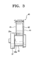
- the initial position controlling protuberance 35a is formed on the housing 35 at a position between the phase protuberances 35b and 35c, where the initial position controlling protuberance 35a itself is interfered with the switch member 45 upon turn-on of the solenoid unit 40. Namely, as shown in Figure 3, during the on-state where the switch member 45 is attached to the operating unit 43, while the driving gear 37 and the housing 35 are rotated together, the initial position controlling protuberance 35a is interfered with the switch member 45. Therefore, at that point, the housing 35 is not rotated and the driving gear 37 runs idle.
- the phase protuberances 35b and 35c are for suppressing rotation of the housing 35 at each of two phase positions of the cam 33 once the initial position has been determined as described above, and are projected at an 180 degree interval with respect to each other on the housing 35.
- the phase protuberances 35b and 35c are symmetric with respect to each other around the shaft 31.
- the phase protuberances 35b and 35c are positioned on the same circumferential line of the housing 35, and each is positioned, to form an angle of 90 degrees with respect to the initial position controlling protuberance 35a.
- phase protuberances 35b and 35c having such construction control a phase of the cam 33 by being interfered with the switch member 45 and suppressing rotation of the housing 35 when the solenoid unit 40 is in the off-state as shown in Figure 2.
- the switch member 45 comes into contact with the second phase protuberance 35c, suppressing rotation of the housing 35.
- the solenoid unit 40 is instantly turned-on and off while the driving gear 37 is being rotated.
- the switch member 45 is detached from the second phase protuberance 35c and restored to its original position and subsequently is rotated as much as 180 degrees, then the first phase protuberance 35b touches or interferes with the switch member 45, whereby the position of the housing 35 is fixed. Therefore, the cam 33 is maintained at the first phase position.
- the solenoid unit 40 is turned on when power is transferred to the driving gear 37. Then, as shown in Figure 3, the switch member 45 is attached to the operating unit 43. After that, while rotating together with the driving gear 37, the housing 35 stops the moment the controlling protuberance 35a comes into contact with the switch member 45. As described, when the controlling protuberance 35a is attached to the switch member 45 the initial status of the cam 33 is set. As shown in Figure 4., the initial position of the cam 33 is such that the long radius of the cam 33 is horizontally positioned.
- the solenoid unit 40 is turned off. Then, the switch member 45 is separated from the operating unit 43 and moved to the position shown in Figure 2. This separates the controlling protuberance 35a from the switch member 45 and the housing 35 is rotated together with the driving gear 37. When rotated approximately 90 degrees, the housing 35 stops the moment the first phase protuberance 35b comes into contact with the switch member 45, becoming the state as shown in Figure 5. Namely, if the first phase protuberance 35b is hooked at the switch member 45, power is not transferred to the housing 35, thus the cam 33 remains fixed at the first phase.
- the solenoid unit 40 is instantly turned on and off (with an interval of about 1-2 seconds) . Then, while the switch member 45 is separated from the first phase protuberance 35b and instantly attached to and detached from the operating unit 43, the housing 35 is rotated as shown in Figure 6. Therefore, the cam 33 is rotated, changing its phase. Eventually, as shown in Figure 7, the second phase protuberance 35c is hooked at the switch member 45 that has been restored to the off-state, and rotation of the housing 35 is stopped. The cam 33 is then fixed in position at the second phase where the long radius of the cam 33 faces the upper side. In order to maintain the position of the cam 33 at the second phase, the solenoid unit 40 is instantly turned off. To change the position of the cam 33 to the first phase, the solenoid unit 40 is cycled on and off again.
- the solenoid is maintained at the on-state only to set the initial position of the cam, and remains in the off-state once the phase has been determined, thus power consumption could be reduced.
- the phase of the cam is easily changed through on/off cycles of the solenoid unit.
Abstract
Description
- The present invention relates to clutch apparatus for controlling two-phase positions of a rotating body.
- Generally, in the case of a laser color printer, a plurality of developing units for developing an image for each color is installed around a photoconductive medium. Therefore, if the developing unit for each color sequentially forms a color image on the photoconductive medium, the formed color images are sequentially transferred to and overlapped on a transferring belt. After that, the overlapped color images formed in such a manner are transferred to a transferring roller rotated by contacting the transferring belt and a paper passing through the transferring belts and the transferring roller. Finally, a paper on which the color image is transferred is discharged after passing through a fixing unit. The laser color printer operating in such a manner has a cam operating apparatus capable of separating the transferring roller from the transferring belt while the color images are formed and overlapped on the transferring belt, and of bringing the transferring roller into contact with the transferring belt so that the color images are completely formed and overlapped.
- Also, the cam operating apparatus selectively operates on or off with the help of a clutch apparatus capable of controlling two-phase positions, thereby controlling a position of a member such as the transferring roller for which two-phase position control is required.
- Figure 1 shows a conventional clutch apparatus for two-phase position control, which includes: an
axis part 10 on which ashaft 12 having acam 11 is fixed; adriving gear 13 having a spring clutch (not shown) intervened, for being selectively rotatable with respect to theaxis part 10; and asolenoid 20 on which theaxis part 10 is supported in a rotatable manner, for controlling rotational position by selectively providing a load on the axis part. - According to the foregoing construction, if the
solenoid 20 is turned on, while thedriving gear 13 and theshaft 12 are rotated together by clutch operation, thefirst phase protuberance 10a projected on the outer periphery of theaxis part 10 is hooked by aswitch member 21 of thesolenoid 20 as shown by a virtual line. Thus, at this status, the first phase of thecam 11 is position-controlled. - Also, in order to perform position control for the second phase of the
cam 11 by rotating thecam 11 as much as 180 degrees, thesolenoid 20 is turned off. Then, theswitch member 21 is moved to a position as shown by a solid line. After that, while drivinggear 13 is rotated together with theshaft 12 and theaxis part 10, thesecond phase protuberance 10b is hooked by theswitch member 21. At that moment, rotation of theshaft 12 is stopped by clutch operation. By such operation, the second phase of thecam 11 is position-controlled. - The conventional clutch apparatus having the foregoing construction should constantly maintain the solenoid at its on-status in order to maintain any position out of two phase-positions. In that case, power consumption increases constantly, and the
solenoid 20 is overheated, so that magnetic force weakens and the sticking force of theswitch member 21 deteriorates. Therefore, there may occur a case that position control is not properly performed. Also, theswitch member 21 is magnetized, so that the separating time is lengthened when the solenoid is turned off, whereby exact cam operation is not appropriately performed. - Accordingly, preferred embodiments of the present invention aim to solve the above-mentioned problems occurring in the related art, and an aim of preferred embodiments of the present invention is to provide a clutch apparatus having an improved structure, capable of performing two-phase position control using low power.
- In an aspect of the present invention a clutch apparatus is provided for performing two-phase position control for a two phase-positioned object installed on a shaft, the clutch apparatus comprising: a clutch housing for rotating together with the shaft while supporting the same; a driving gear installed on the housing, for being rotatable and for selectively driving the housing in a rotatable manner with the help of a clutch intervened between the housing and the driving gear; and a solenoid unit for supporting the housing and for being selectively on/off controlled, wherein the housing has an initial position controlling protuberance interfered with the solenoid unit in its on-state, for determining an initial position of the object, and a pair of phase protuberances interfered with the solenoid unit in its off-state, for suppressing rotation of the housing at each of the two phase positions of the object.
- Suitably, the pair of the phase protuberances is projected on the outer periphery of the housing, and correspond to a position of the switch member in its off-state that is changed by on/off operation of the solenoid unit.
- Suitably, the pair of the phase protuberances is positioned on the same circumference in the outer periphery of the housing.
- Suitably, a pair of the phase protuberances is installed symmetrically with respect to the shaft.
- Suitably, the initial position controlling protuberance is prepared on a position that forms an angle of 90 degrees in the circumferential direction with respect to each of the phase protuberances.
- Suitably, interference between the solenoid unit and either of the phase protuberances is released by instant on/off operation of the solenoid unit so that phase conversion may be possible.
- The present invention also provides a position control clutch device having a driving gear and clutch connectable for rotation with a housing. A shaft is connectable for rotation with the housing at one end and has an object at the opposite end and a solenoid unit that is adapted to rotatably support the housing and for selectively engaging protuberances on the surface of the housing with a switch member. The switch member engages an initial position controlling protuberance when the solenoid unit is in an on state and the switch member selectively engages either a first phase protuberance or a second phase protuberance when the solenoid is in an off state, whereby the position of the object at the end of the shaft is controlled in set phases by turning the solenoid on and off.
- The present invention also provides a position control clutch device having a housing rotatably coupled to a shaft, where the shaft has a cam at a free end that is in common rotation with the shaft. A driving gear and clutch are connectable for selective rotation with the housing. A solenoid unit is adapted to rotatably support the housing and for selectively engaging the housing with a switch member, where the switch member selectively engages an initial position controlling protuberance on the surface of the housing when the solenoid unit is on, and a first phase protuberance or a second phase protuberance on the surface of the housing when the solenoid is off. Thus, the position of the cam may change phase by cycling the solenoid on and off.
- Additional aspects and/or advantages of the invention will be set forth in part in the description which follows and, in part, will be obvious from the description, or may be learned by practice of the invention.
- The present invention will become more apparent from the following detailed description of an embodiment, by way of example only, when taken in conjunction with the accompanying drawings, in which:
- Figure 1 is a side view schematically showing a conventional clutch apparatus;
- Figure 2 and Figure 3 are side views schematically showing a clutch apparatus according to an embodiment of the present invention; and
- Figure 4 through Figure 7 are front views explaining the operation of a clutch apparatus according to an embodiment of the present invention, respectively.
-
- Reference will now be made in detail to the present embodiment of the present invention, an example of which is illustrated in the accompanying drawings, wherein like reference numerals refer to like elements throughout. The embodiment is described below in order to explain the present invention by referring to the figures. The matters defined in the description such as a detailed construction and elements are simply provided to assist in a comprehensive understanding of the invention. Thus, it is apparent that the present invention can be carried out without those defined matters. Also, well-known functions or constructions are not described in detail since they would obscure the invention in unnecessary detail.
- Referring to Figure 2, a clutch apparatus according to an embodiment of the present invention is for controlling a two phase-positioned object installed on a
shaft 31, i.e., two-phase positions of acam 33. The clutch apparatus has aclutch housing 35 joined to theshaft 31, for rotating together with theshaft 31; adriving gear 37 joined to thehousing 35; and asolenoid unit 40, that may be turned on or off, for supporting thehousing 35. - The
eccentric cam 33 is supported by and rotated together with theshaft 31. Theshaft 31 is fit into an axis hole of thehousing 35 and is rotated together with thehousing 35. Thehousing 35 is supported in a rotatable manner by a supportingframe 41 of thesolenoid 40. - Also, a clutch (not shown) is intervened between the
housing 35 and thedriving gear 37. Namely, a spring clutch, which is widely used and is well known, is installed between thehousing 35 and thedriving gear 37, for selectively delivering the rotational force of thedriving gear 37 to thehousing 35. Therefore, if a load is provided on thehousing 35, thedriving gear 37 runs idle. Here, thedriving gear 37 is given power for rotation from a predetermined power transferring unit. - The
solenoid unit 40 has a supportingframe 41 for supporting thehousing 35 in a rotatable manner; asolenoid operating unit 43 installed in the supportingframe 41; aswitch member 45 that is selectively attached to and separated from thesolenoid operating unit 43 by turning thesolenoid operating unit 43 on or off. Theswitch member 45 is elastically-biased by aspring 47, to maintain separation from theoperating unit 43 upon turn-on of theoperating unit 43 as shown in Figure 2. - The
housing 35 has, on its outer periphery, an initialposition controlling protuberance 35a for determining an initial position of thecam 33 and a pair ofphase protuberances - The initial
position controlling protuberance 35a is formed on thehousing 35 at a position between thephase protuberances position controlling protuberance 35a itself is interfered with theswitch member 45 upon turn-on of thesolenoid unit 40. Namely, as shown in Figure 3, during the on-state where theswitch member 45 is attached to theoperating unit 43, while thedriving gear 37 and thehousing 35 are rotated together, the initialposition controlling protuberance 35a is interfered with theswitch member 45. Therefore, at that point, thehousing 35 is not rotated and thedriving gear 37 runs idle. - The
phase protuberances housing 35 at each of two phase positions of thecam 33 once the initial position has been determined as described above, and are projected at an 180 degree interval with respect to each other on thehousing 35. Thephase protuberances shaft 31. Also, thephase protuberances housing 35, and each is positioned, to form an angle of 90 degrees with respect to the initialposition controlling protuberance 35a. Thephase protuberances cam 33 by being interfered with theswitch member 45 and suppressing rotation of thehousing 35 when thesolenoid unit 40 is in the off-state as shown in Figure 2. As shown in Figure 2, in the second phase where the long radius of the cam faces the upper side, theswitch member 45 comes into contact with thesecond phase protuberance 35c, suppressing rotation of thehousing 35. In order to move thecam 33 to the first phase where the long radius of thecam 33 is positioned to the lower side, thesolenoid unit 40 is instantly turned-on and off while thedriving gear 37 is being rotated. Then, theswitch member 45 is detached from thesecond phase protuberance 35c and restored to its original position and subsequently is rotated as much as 180 degrees, then thefirst phase protuberance 35b touches or interferes with theswitch member 45, whereby the position of thehousing 35 is fixed. Therefore, thecam 33 is maintained at the first phase position. - Operation of the clutch apparatus according to an embodiment of the present invention having the foregoing construction will be described in more detail with reference to Figure 2 through Figure 7 in the following.
- To determine the initial position of the
cam 33, thesolenoid unit 40 is turned on when power is transferred to thedriving gear 37. Then, as shown in Figure 3, theswitch member 45 is attached to the operatingunit 43. After that, while rotating together with thedriving gear 37, thehousing 35 stops the moment the controllingprotuberance 35a comes into contact with theswitch member 45. As described, when the controllingprotuberance 35a is attached to theswitch member 45 the initial status of thecam 33 is set. As shown in Figure 4., the initial position of thecam 33 is such that the long radius of thecam 33 is horizontally positioned. - To move the position of the
cam 33 to the first phase where the long radius of thecam 33 faces the lower side, thesolenoid unit 40 is turned off. Then, theswitch member 45 is separated from the operatingunit 43 and moved to the position shown in Figure 2. This separates the controllingprotuberance 35a from theswitch member 45 and thehousing 35 is rotated together with thedriving gear 37. When rotated approximately 90 degrees, thehousing 35 stops the moment thefirst phase protuberance 35b comes into contact with theswitch member 45, becoming the state as shown in Figure 5. Namely, if thefirst phase protuberance 35b is hooked at theswitch member 45, power is not transferred to thehousing 35, thus thecam 33 remains fixed at the first phase. - Starting from the above state shown in Figure 5, in order to change the position of the
cam 33 to the second phase, thesolenoid unit 40 is instantly turned on and off (with an interval of about 1-2 seconds) . Then, while theswitch member 45 is separated from thefirst phase protuberance 35b and instantly attached to and detached from the operatingunit 43, thehousing 35 is rotated as shown in Figure 6. Therefore, thecam 33 is rotated, changing its phase. Eventually, as shown in Figure 7, thesecond phase protuberance 35c is hooked at theswitch member 45 that has been restored to the off-state, and rotation of thehousing 35 is stopped. Thecam 33 is then fixed in position at the second phase where the long radius of thecam 33 faces the upper side. In order to maintain the position of thecam 33 at the second phase, thesolenoid unit 40 is instantly turned off. To change the position of thecam 33 to the first phase, thesolenoid unit 40 is cycled on and off again. - As is apparent from the foregoing discussion regarding the clutch apparatus according to an embodiment of the present invention, the solenoid is maintained at the on-state only to set the initial position of the cam, and remains in the off-state once the phase has been determined, thus power consumption could be reduced. The phase of the cam is easily changed through on/off cycles of the solenoid unit.
- Also, as the phase of the cam is maintained at the off-status, overheating of the solenoid is prevented and its life cycle is extended and malfunction is prevented.
- While the present invention has been particularly shown and described with reference to exemplary embodiments thereof, it will be understood by those of ordinary skill in the art that various changes in form and details may be made therein without departing from the spirit and scope of the invention as defined by the accompanying claims and their equivalents.
- Attention is directed to all papers and documents which are filed concurrently with or previous to this specification in connection with this application and which are open to public inspection with this specification, and the contents of all such papers and documents are incorporated herein by reference.
- All of the features disclosed in this specification (including any accompanying claims, abstract and drawings), and/or all of the steps of any method or process so disclosed, may be combined in any combination, except combinations where at least some of such features and/or steps are mutually exclusive.
- Each feature disclosed in this specification (including any accompanying claims, abstract and drawings) may be replaced by alternative features serving the same, equivalent or similar purpose, unless expressly stated otherwise. Thus, unless expressly stated otherwise, each feature disclosed is one example only of a generic series of equivalent or similar features.
- The invention is not restricted to the details of the foregoing embodiment(s). The invention extends to any novel one, or any novel combination, of the features disclosed in this specification (including any accompanying claims, abstract and drawings), or to any novel one, or any novel combination, of the steps of any method or process so disclosed.
Claims (6)
- A clutch apparatus for performing two-phase position control for a two phase-positioned object installed on a shaft (31), the clutch apparatus comprising:a clutch housing (35) for rotating together with the shaft (31), while supporting the shaft (31);a driving gear (37) installed on the housing (35), for being rotatable and for selectively driving the housing (35) in a rotatable manner with the help of a clutch intervened between the housing (35) and the driving gear (37); anda solenoid unit (40) for supporting the housing (35) and selectively on/off-controlled, wherein the housing (35) has an initial position controlling protuberance (35a) interfered with the solenoid unit (40) in its on-state, for determining an initial position of the object, and a pair of phase protuberances (35b, 35c) interfered with the solenoid unit (40) in its off-state, for suppressing rotation of the housing (35) at each of the two phase positions of the object.
- The apparatus according to claim 1, wherein the pair of the phase protuberances (35b, 35c) is projected on an outer periphery of the housing (35), for corresponding to a position of a switch member (45) in its off-state that is changed by on/off operation of the solenoid unit (40).
- The apparatus according to claim 2, wherein the pair of the phase protuberances (35b, 35c) is positioned on the same circumference in the outer periphery of the housing (35).
- The apparatus according to claim 2 or claim 3, wherein the phase protuberances (35b, 35c) are installed symmetrically with respect to the shaft (31).
- The apparatus according to any preceding claim, wherein the initial position controlling protuberance (35a) is prepared on a position that forms an angle of 90 degrees in a circumferential direction with respect to each of the phase protuberances (35b, 35c).
- The apparatus according to any preceding claim, wherein interference between the solenoid unit (40) and either of a pair of the phase protuberances (35b or 35c) is released by instant on/off-operation of the solenoid unit (40) so that phase conversion may be possible.
Applications Claiming Priority (2)
| Application Number | Priority Date | Filing Date | Title |
|---|---|---|---|
| KR10-2002-0081463A KR100464091B1 (en) | 2002-12-18 | 2002-12-18 | clutch apparatus |
| KR2002081463 | 2002-12-18 |
Publications (2)
| Publication Number | Publication Date |
|---|---|
| EP1431216A1 true EP1431216A1 (en) | 2004-06-23 |
| EP1431216B1 EP1431216B1 (en) | 2005-11-02 |
Family
ID=36371768
Family Applications (1)
| Application Number | Title | Priority Date | Filing Date |
|---|---|---|---|
| EP03257678A Expired - Fee Related EP1431216B1 (en) | 2002-12-18 | 2003-12-05 | Clutch apparatus |
Country Status (4)
| Country | Link |
|---|---|
| US (1) | US7021439B2 (en) |
| EP (1) | EP1431216B1 (en) |
| KR (1) | KR100464091B1 (en) |
| DE (1) | DE60302133T2 (en) |
Families Citing this family (2)
| Publication number | Priority date | Publication date | Assignee | Title |
|---|---|---|---|---|
| US20060257313A1 (en) * | 2005-02-17 | 2006-11-16 | Alan Cisar | Hydrolysis of chemical hydrides utilizing hydrated compounds |
| KR100619075B1 (en) | 2005-04-06 | 2006-08-31 | 삼성전자주식회사 | Rotating force clutch apparatus and image forming apparatus comprising the same |
Citations (4)
| Publication number | Priority date | Publication date | Assignee | Title |
|---|---|---|---|---|
| US4529188A (en) * | 1983-07-05 | 1985-07-16 | Xerox Corporation | Sheet feeding and registration apparatus |
| JPS60204533A (en) * | 1984-03-30 | 1985-10-16 | Canon Inc | Spring clutch |
| EP0464785A2 (en) * | 1990-07-04 | 1992-01-08 | Canon Kabushiki Kaisha | Sheet feeding apparatus |
| EP0921082A1 (en) * | 1997-12-08 | 1999-06-09 | Samsung Electronics Co., Ltd. | Spring clutch control mechanism for a sheet feeding device |
Family Cites Families (9)
| Publication number | Priority date | Publication date | Assignee | Title |
|---|---|---|---|---|
| JPS6049772B2 (en) * | 1976-10-22 | 1985-11-05 | キヤノン株式会社 | spring clutch device |
| US4191283A (en) * | 1978-08-24 | 1980-03-04 | Warner Electric Brake & Clutch Company | Helical spring coupling with programmable control collar |
| US4586813A (en) * | 1983-09-19 | 1986-05-06 | Kabushiki Kaisha Toshiba | Image forming apparatus |
| JPS61229728A (en) * | 1985-04-04 | 1986-10-14 | Konishiroku Photo Ind Co Ltd | Paper feeder |
| JPH0819969B2 (en) * | 1986-09-30 | 1996-03-04 | 三田工業株式会社 | Electromagnetically controlled spring clutch mechanism |
| JPH03107619A (en) * | 1989-09-22 | 1991-05-08 | Minolta Camera Co Ltd | Spring clutch |
| JP2911614B2 (en) * | 1990-12-26 | 1999-06-23 | キヤノン株式会社 | Rotation control device and sheet feeding device having rotation control device |
| JP3272910B2 (en) * | 1995-06-16 | 2002-04-08 | シャープ株式会社 | Spring clutch mechanism and paper feeder clutch mechanism |
| US5860645A (en) * | 1995-10-20 | 1999-01-19 | Canon Kabushiki Kaisha | Sheet supplying apparatus |
-
2002
- 2002-12-18 KR KR10-2002-0081463A patent/KR100464091B1/en not_active IP Right Cessation
-
2003
- 2003-12-05 DE DE60302133T patent/DE60302133T2/en not_active Expired - Lifetime
- 2003-12-05 EP EP03257678A patent/EP1431216B1/en not_active Expired - Fee Related
- 2003-12-17 US US10/736,845 patent/US7021439B2/en not_active Expired - Fee Related
Patent Citations (4)
| Publication number | Priority date | Publication date | Assignee | Title |
|---|---|---|---|---|
| US4529188A (en) * | 1983-07-05 | 1985-07-16 | Xerox Corporation | Sheet feeding and registration apparatus |
| JPS60204533A (en) * | 1984-03-30 | 1985-10-16 | Canon Inc | Spring clutch |
| EP0464785A2 (en) * | 1990-07-04 | 1992-01-08 | Canon Kabushiki Kaisha | Sheet feeding apparatus |
| EP0921082A1 (en) * | 1997-12-08 | 1999-06-09 | Samsung Electronics Co., Ltd. | Spring clutch control mechanism for a sheet feeding device |
Non-Patent Citations (1)
| Title |
|---|
| PATENT ABSTRACTS OF JAPAN vol. 010, no. 059 (M - 459) 8 March 1986 (1986-03-08) * |
Also Published As
| Publication number | Publication date |
|---|---|
| KR20040054428A (en) | 2004-06-25 |
| US20040124056A1 (en) | 2004-07-01 |
| KR100464091B1 (en) | 2005-01-03 |
| DE60302133D1 (en) | 2005-12-08 |
| EP1431216B1 (en) | 2005-11-02 |
| DE60302133T2 (en) | 2006-06-01 |
| US7021439B2 (en) | 2006-04-04 |
Similar Documents
| Publication | Publication Date | Title |
|---|---|---|
| JP3150187B2 (en) | Image forming device | |
| JP3884960B2 (en) | Driving device and color image forming apparatus | |
| US5534984A (en) | Recording apparatus having a transfer drum shifting device | |
| EP0895134A2 (en) | An image forming apparatus selectively operating one of a plurality of developing units and a method for controlling a switching operation for the developing units | |
| JP4034271B2 (en) | Transfer device | |
| EP1431216B1 (en) | Clutch apparatus | |
| JP7009100B2 (en) | Fixing device and image forming device | |
| JP2007139915A (en) | Image forming device | |
| CN100510984C (en) | Image forming apparauts | |
| US7680441B2 (en) | Image forming apparatus | |
| JPH1010948A (en) | Cleaning device for movable surface of printer or copying machine | |
| CN105404122A (en) | Imaging apparatus | |
| CN109312827A (en) | Driving device and imaging device including the driving device | |
| JP4943036B2 (en) | Driving device used in image forming apparatus | |
| JP2006215237A (en) | Image forming apparatus | |
| US5815772A (en) | Driving system for a detachable unit and of using same | |
| JP4864448B2 (en) | Driving device used in image forming apparatus | |
| JP4845588B2 (en) | Image heating device | |
| JP4510774B2 (en) | Driving device used in image forming apparatus | |
| JP2005326719A (en) | Image forming apparatus | |
| JP2014034447A (en) | Belt device, belt fixing device, and image forming apparatus equipped with the belt fixing device | |
| JP4433122B2 (en) | Belt drive device and image forming apparatus | |
| JP2002116623A (en) | Image forming device | |
| JP2000250377A (en) | Image forming device | |
| JP2002278346A (en) | Fixing device for image forming apparatus |
Legal Events
| Date | Code | Title | Description |
|---|---|---|---|
| PUAI | Public reference made under article 153(3) epc to a published international application that has entered the european phase |
Free format text: ORIGINAL CODE: 0009012 |
|
| 17P | Request for examination filed |
Effective date: 20031224 |
|
| AK | Designated contracting states |
Kind code of ref document: A1 Designated state(s): AT BE BG CH CY CZ DE DK EE ES FI FR GB GR HU IE IT LI LU MC NL PT RO SE SI SK TR |
|
| AX | Request for extension of the european patent |
Extension state: AL LT LV MK |
|
| AKX | Designation fees paid |
Designated state(s): DE FR GB NL |
|
| GRAP | Despatch of communication of intention to grant a patent |
Free format text: ORIGINAL CODE: EPIDOSNIGR1 |
|
| GRAS | Grant fee paid |
Free format text: ORIGINAL CODE: EPIDOSNIGR3 |
|
| GRAA | (expected) grant |
Free format text: ORIGINAL CODE: 0009210 |
|
| AK | Designated contracting states |
Kind code of ref document: B1 Designated state(s): DE FR GB NL |
|
| REG | Reference to a national code |
Ref country code: GB Ref legal event code: FG4D |
|
| REF | Corresponds to: |
Ref document number: 60302133 Country of ref document: DE Date of ref document: 20051208 Kind code of ref document: P |
|
| ET | Fr: translation filed | ||
| PLBE | No opposition filed within time limit |
Free format text: ORIGINAL CODE: 0009261 |
|
| STAA | Information on the status of an ep patent application or granted ep patent |
Free format text: STATUS: NO OPPOSITION FILED WITHIN TIME LIMIT |
|
| 26N | No opposition filed |
Effective date: 20060803 |
|
| PGFP | Annual fee paid to national office [announced via postgrant information from national office to epo] |
Ref country code: DE Payment date: 20131202 Year of fee payment: 11 Ref country code: GB Payment date: 20131127 Year of fee payment: 11 |
|
| PGFP | Annual fee paid to national office [announced via postgrant information from national office to epo] |
Ref country code: NL Payment date: 20131203 Year of fee payment: 11 Ref country code: FR Payment date: 20131202 Year of fee payment: 11 |
|
| REG | Reference to a national code |
Ref country code: DE Ref legal event code: R119 Ref document number: 60302133 Country of ref document: DE |
|
| REG | Reference to a national code |
Ref country code: NL Ref legal event code: V1 Effective date: 20150701 |
|
| REG | Reference to a national code |
Ref country code: NL Ref legal event code: V1 Effective date: 20150701 |
|
| GBPC | Gb: european patent ceased through non-payment of renewal fee |
Effective date: 20141205 |
|
| REG | Reference to a national code |
Ref country code: FR Ref legal event code: ST Effective date: 20150831 |
|
| PG25 | Lapsed in a contracting state [announced via postgrant information from national office to epo] |
Ref country code: NL Free format text: LAPSE BECAUSE OF NON-PAYMENT OF DUE FEES Effective date: 20150701 |
|
| PG25 | Lapsed in a contracting state [announced via postgrant information from national office to epo] |
Ref country code: GB Free format text: LAPSE BECAUSE OF NON-PAYMENT OF DUE FEES Effective date: 20141205 Ref country code: DE Free format text: LAPSE BECAUSE OF NON-PAYMENT OF DUE FEES Effective date: 20150701 |
|
| PG25 | Lapsed in a contracting state [announced via postgrant information from national office to epo] |
Ref country code: FR Free format text: LAPSE BECAUSE OF NON-PAYMENT OF DUE FEES Effective date: 20141231 |
|
| REG | Reference to a national code |
Ref country code: GB Ref legal event code: 732E Free format text: REGISTERED BETWEEN 20170406 AND 20170412 |
|
| REG | Reference to a national code |
Ref country code: FR Ref legal event code: TP Owner name: S-PRINTING SOLUTION CO., LTD., KR Effective date: 20170912 |