EP1431193A2 - Container handles - Google Patents
Container handles Download PDFInfo
- Publication number
- EP1431193A2 EP1431193A2 EP03078892A EP03078892A EP1431193A2 EP 1431193 A2 EP1431193 A2 EP 1431193A2 EP 03078892 A EP03078892 A EP 03078892A EP 03078892 A EP03078892 A EP 03078892A EP 1431193 A2 EP1431193 A2 EP 1431193A2
- Authority
- EP
- European Patent Office
- Prior art keywords
- container
- handle section
- cavity
- gripping layer
- container according
- Prior art date
- Legal status (The legal status is an assumption and is not a legal conclusion. Google has not performed a legal analysis and makes no representation as to the accuracy of the status listed.)
- Granted
Links
Images


Classifications
-
- B—PERFORMING OPERATIONS; TRANSPORTING
- B65—CONVEYING; PACKING; STORING; HANDLING THIN OR FILAMENTARY MATERIAL
- B65D—CONTAINERS FOR STORAGE OR TRANSPORT OF ARTICLES OR MATERIALS, e.g. BAGS, BARRELS, BOTTLES, BOXES, CANS, CARTONS, CRATES, DRUMS, JARS, TANKS, HOPPERS, FORWARDING CONTAINERS; ACCESSORIES, CLOSURES, OR FITTINGS THEREFOR; PACKAGING ELEMENTS; PACKAGES
- B65D1/00—Containers having bodies formed in one piece, e.g. by casting metallic material, by moulding plastics, by blowing vitreous material, by throwing ceramic material, by moulding pulped fibrous material, by deep-drawing operations performed on sheet material
- B65D1/22—Boxes or like containers with side walls of substantial depth for enclosing contents
- B65D1/24—Boxes or like containers with side walls of substantial depth for enclosing contents with moulded compartments or partitions
- B65D1/243—Crates for bottles or like containers
-
- B—PERFORMING OPERATIONS; TRANSPORTING
- B65—CONVEYING; PACKING; STORING; HANDLING THIN OR FILAMENTARY MATERIAL
- B65D—CONTAINERS FOR STORAGE OR TRANSPORT OF ARTICLES OR MATERIALS, e.g. BAGS, BARRELS, BOTTLES, BOXES, CANS, CARTONS, CRATES, DRUMS, JARS, TANKS, HOPPERS, FORWARDING CONTAINERS; ACCESSORIES, CLOSURES, OR FITTINGS THEREFOR; PACKAGING ELEMENTS; PACKAGES
- B65D2501/00—Containers having bodies formed in one piece
- B65D2501/24—Boxes or like containers with moulded compartments or partitions
- B65D2501/24006—Details relating to bottle crates
- B65D2501/24012—Materials
- B65D2501/24019—Mainly plastics
-
- B—PERFORMING OPERATIONS; TRANSPORTING
- B65—CONVEYING; PACKING; STORING; HANDLING THIN OR FILAMENTARY MATERIAL
- B65D—CONTAINERS FOR STORAGE OR TRANSPORT OF ARTICLES OR MATERIALS, e.g. BAGS, BARRELS, BOTTLES, BOXES, CANS, CARTONS, CRATES, DRUMS, JARS, TANKS, HOPPERS, FORWARDING CONTAINERS; ACCESSORIES, CLOSURES, OR FITTINGS THEREFOR; PACKAGING ELEMENTS; PACKAGES
- B65D2501/00—Containers having bodies formed in one piece
- B65D2501/24—Boxes or like containers with moulded compartments or partitions
- B65D2501/24006—Details relating to bottle crates
- B65D2501/24363—Handles
- B65D2501/24509—Integral handles
- B65D2501/24515—Integral handles provided on the side wall
-
- B—PERFORMING OPERATIONS; TRANSPORTING
- B65—CONVEYING; PACKING; STORING; HANDLING THIN OR FILAMENTARY MATERIAL
- B65D—CONTAINERS FOR STORAGE OR TRANSPORT OF ARTICLES OR MATERIALS, e.g. BAGS, BARRELS, BOTTLES, BOXES, CANS, CARTONS, CRATES, DRUMS, JARS, TANKS, HOPPERS, FORWARDING CONTAINERS; ACCESSORIES, CLOSURES, OR FITTINGS THEREFOR; PACKAGING ELEMENTS; PACKAGES
- B65D2501/00—Containers having bodies formed in one piece
- B65D2501/24—Boxes or like containers with moulded compartments or partitions
- B65D2501/24006—Details relating to bottle crates
- B65D2501/24866—Other details
- B65D2501/24872—Information, identification or detection means
- B65D2501/24904—Engraved or moulded indicia
-
- B—PERFORMING OPERATIONS; TRANSPORTING
- B65—CONVEYING; PACKING; STORING; HANDLING THIN OR FILAMENTARY MATERIAL
- B65D—CONTAINERS FOR STORAGE OR TRANSPORT OF ARTICLES OR MATERIALS, e.g. BAGS, BARRELS, BOTTLES, BOXES, CANS, CARTONS, CRATES, DRUMS, JARS, TANKS, HOPPERS, FORWARDING CONTAINERS; ACCESSORIES, CLOSURES, OR FITTINGS THEREFOR; PACKAGING ELEMENTS; PACKAGES
- B65D2525/00—Details of other kinds or types of rigid or semi-rigid containers
- B65D2525/28—Handles
- B65D2525/281—Details relating to handles
- B65D2525/289—Handgrip-element made separately from the handle
Definitions
- the present invention relates to handles for a container. More in particular, the present invention relates to a plastic container for storing and/or transporting objects, such as bottles, which container has at least one handle provided with a relatively soft gripping layer.
- a container of this type is disclosed in, for example, European Patent Application EP 1 000 865 (D W Plastics). Further details of such a container and its gripping layer are described in European Patent Application EP 03078279.1 (D W Plastics).
- handles are provided with anchoring means for providing a secure engagement of the gripping layer(s).
- the inventor has realised that the design of the handles can be further improved so as to provide further advantageous features.
- the gripping layer of containers may be provided in various colours. Even if the gripping material has approximately the same colour as the container, the different properties of the gripping material make the gripping areas clearly discemable.
- the gripping layer typically has a thickness of at least one millimeter, often several millimeters, so that a gripping layer remains visible for a long time, even if it wears off slightly.
- the present invention solves the problem of providing wear-resistant indicia by utilizing the gripping layer material which is already provided in many containers.
- the present invention therefore provides a container for storing and/or transporting objects, the container being made of a plastics material and comprising a base extending in a first direction and at least two side walls extending from the base in a second direction, the container being provided with at least one handle section provided at least partially with a gripping layer made out of a material having a smaller hardness than said plastics material, wherein the handle section is provided with at least one view hole through which the material of the gripping layer is visible from the outside the handle section, and wherein the at least one view hole is shaped so as to form a discernible indication.
- the indication thus formed may constitute at least one alphanumeric character.
- a plurality of view holes may form a name, such as a brand or type name.
- At least some view holes may be shaped to form gripping ribs. It is also possible to provide gripping ribs which are shaped to form indications, thus combining the functions of gripping and of indicating.
- the relatively soft material may be a thermoplastic material.
- a suitable material is SEBS (styrene ethylene butadyene styrene) which is commercially available as DryflexTM, although other relatively soft materials may also be used.
- SEBS styrene ethylene butadyene styrene
- Relatively soft typically means softer than the walls of the container.
- a cavity may be present that connects the view holes, but this is not essential and each view hole may individually be provided with relatively soft material. That is, a suitable amount of relatively soft material may be inserted in each view hole, directly in each individual view hole and/or indirectly via a common channel or cavity.
- the present invention utilizes the gripping layer material to providing visible indications.
- This gripping layer material is already used in many containers and therefore no additional material is necessary.
- the indications may have the same colour as the gripping layer, thus eliminating the need for an additional dye, although it is possible to use different colours.
- indications could be provided by using at least two differently coloured (relatively hard) plastics material to produce the container. However, this would have the disadvantage of requiring three materials if a gripping layer were to be provided.
- the handle part of a plastic container such as a crate, often has an increased (wall) thickness so as to provide sufficient strength.
- This increased thickness may, however, be a disadvantage during the manufacture of the container, especially when the handle part is integral with the crate.
- the increased thickness of the material results in a strongly increased cooling down time of the container after the moulding process, thus increasing the production cycle time.
- a part having a relatively large thickness may give rise to increased shrinkage and/or deformation.
- the present invention further provides a container for storing and/or transporting objects, the container being made of a plastics material and comprising a base extending in a first direction and at least two side walls extending from the base in a second, substantially perpendicular direction, the container being provided with at least one handle section covered at least partially by a gripping layer made out of a material having a smaller hardness than said plastics material, wherein the handle section is substantially U-shaped so as to provide a cavity.
- the effective thickness of the handle section may be significantly reduced while substantially preserving the strength of the handle.
- a cavity that is a hollow section open to the outside, can easily be provided by a suitable shape of the mould in which the container (or separate handle section) is made, without the need for "air moulding" or similar techniques.
- the cavity may remain empty, that is, filled with air, it is preferred that the cavity is filled with the (preferably thermoplastic) material constituting the gripping layer. This both reinforces the handle section and may provide additional anchoring of the relatively soft material. In addition, filling the cavity with the material of the gripping layer closes off the cavity, thus preventing the accumulation of dirt.
- the cavity faces upwards. That is, the cavity is (at least initially) open at the top end. This facilitates the injection of the relatively soft gripping layer material, as the material can be injected from above.
- the cavity faces downwards. That is, the cavity is (at least initially) open at the bottom end, at the handle opening.
- This embodiment has the advantage that the relatively soft gripping material is not visible at the top of the handle part, which may be preferred for aesthetic reasons.
- the cavity is provided with at least one connecting element which connects opposing walls of the cavity, said connecting element preferably being integral with said walls.
- the connecting element or elements bridge the gap between the walls of the cavity, thus significantly increasing the strength of the handle part. It is preferred that at least two connecting elements are provided, but larger numbers, such as three or four, are also possible.
- the handle section is provided with at least one through-hole through which the material of the gripping layer may extend.
- Two types of through-holes can be distinguished.
- a first type is an anchoring hole which serves to connect two layers or sections of the relatively soft gripping material.
- anchoring holes connect the gripping material inside the cavity with the gripping material (gripping layer) on the outside of the handle part, thus providing an excellent anchoring of the outside layer.
- a second type of through-hole is a view hole through which the material of the gripping layer is visible from outside the handle section.
- Such a view hole may serve to inspect the material in the cavity so as to ascertain that the cavity is properly filled.
- the view hole or holes may be used for providing a visual indication, as discussed above.
- the at least one view hole is shaped so as to form a discernible indication, the indication preferably being an alphanumeric character.
- a plurality of view holes form a name, such as a brand or type name.
- a brand or product indication may be displayed.
- the plurality of view holes may constitute the name of the brewery, the type of beer, and/or the number of bottles and their content.
- view holes as discussed above may also be effected in handle sections where no cavity is present.
- the present invention further provides a handle for use in a container as defined above.
- the handle according to the invention has view holes which allow a relatively soft gripping layer material to be visible, the view holes being shaped so as to provide discernable indications, such as alphanumeric characters.
- the handle may be arranged centrally or in a side wall, and may be integral with the container or separately produced.
- the handle section 6 shown merely by way of non-limiting example in Fig. 1 is arranged above a handle opening 5 in the side wall 3 of a container having an outside A and an inside B .
- a handle arranged in a side wall is shown, the present invention also relates to other handles, such as central handles of crates and similar containers.
- a container in which the present handle section may be used is shown in Fig. 6.
- the handle section 6 shown in Fig. 1 is integral with the side wall 3. This is, however, not essential and separately produced handles can also be envisaged.
- the handle section 6 is provided with a layer 7 of relatively soft material, preferably a thermoplastic material.
- the gripping layer 7 is arranged on both sides of the handle section, the layer facing the inside B of the container extending further than the layer on the opposite side of the handle section.
- a cavity 18 is formed in the handle section 6.
- the cavity 18 is substantially centrally located and is, in the embodiment shown, open at the top surface of the handle section, thus having an approximate U-shape. It should be noted that other embodiments are possible in which the cavity is open towards the bottom surface of the handle section, that is, towards the handle opening 5, thus forming an approximate inverse U-shape. It can also be envisaged that the cavity is open to one side.
- the cavity 18 is filled with the same material as the gripping layer 7.
- An upper through-hole 9 constitutes an anchoring hole through which the material 7 in the cavity 18 is connected to the material 7 at the side of the handle section 6.
- a lower through-hole 9' also constitutes an anchoring hole and connects the layers at the opposite sides of the handle section 6. The through-holes 9 and 9' also serve to distribute the material of the gripping layer 7 during the manufacture thereof.
- the width of the walls of the cavity 18 is much less than the width of the entire handle section, resulting in significantly reduced cooling times and shrinkage problems during the manufacture of the container.
- the relatively soft material 7 may be co-moulded but is preferably injection moulded in a separate mould, soon after the moulding of the container itself.
- connection elements 25 are preferably connected by connecting elements 25.
- connection elements which preferably are integral with the walls of the cavity, greatly increase the overall strength of the handle section.
- a view hole 19 is provided in the front face (facing the outside A) of the handle section 6.
- This view hole 19 allows the material 7 to be visible at the front of the handle section. If the material of the gripping layer 7 has a colour which is different from the material of the container, the material 7 in the view hole 19 is clearly visible from the outside of the container.
- the view hole may form a discernible indication, such as a sign or symbol.
- the view hole 19 constitutes an alphanumeric character. This allows a name or type indication to be displayed, for example the name of a brewery of manufacturer, and/or an indication of the type or quantity of the product carried in the container. This is shown in Fig. 4 where the initials of a manufacturer are displayed by the material 7 in the view holes 19.
- the view hole 19 widens towards the front of the handle section 6. Although this is advantageous, it is not essential and view holes having a substantially uniform diameter can also be envisaged. However, widening the view hole 19 towards the front of the handle section has the advantage that a smaller amount of the relative expensive material 7 is needed. Also, to provide several view holes 19 having different shapes at the front of the handle section, a series of substantially uniform channels can be provided which extend into widened sections having different shapes.
- the view hole 19 is a through-hole which extends from the back of the handle section 6 (where a gripping layer 7 is present) to the front of the same.
- a through hole both provides anchoring of the gripping layer and assists in the moulding of the gripping layer material 7.
- a view hole 19 is not necessarily connected with other parts of the gripping material via a through hole, cavity or channel.
- the material 7 may slightly protrude from the view hole(s) 19 but is preferably substantially flush with the front of the handle section.
- view holes 19 have been modified so as to form ribs of material 7. These ribs may protrude slightly to provide a better grip, or may be substantially flush with the handle section 6'.
- Other view holes 19 form an indication, such as the number of bottles in a crate and the content of each bottle, for example "24 x 25 cl.”.
- such an indication may be formed by gripping layer material having substantially the same colour as the handle or the entire crate, it is preferred that the gripping layer material has a different colour, advantageously a contrasting colour.
- the gripping layer material has a different colour, advantageously a contrasting colour.
- white or yellow markings provide a good contrast and improve the legibility of the indication.
- the handle may be provided with indicia, such as the brand of the product carried in the container and/or the type of packaging of the product.
- the handle of a beer crate could, for example, read "24x0.5", indicating that 24 bottles of 0.5 litres may be carried in this container.
- These indicia are according to the present invention preferably provided by (relatively soft) gripping layer material, although other materials may also be used.
- indicia could be provided in the handle of a crate using HDPE having two different colours. Thus the indications could be provided using a relatively hard material.
- the handle section 6' of Fig. 5 may contain a cavity (18 in Fig. 1) but this is not essential. It is noted that the handle section 6' is designed for use as a central handle in, for example, a crate.
- the ribs of material 7 may, of course, also be applied in side wall handle sections as discussed above with reference to Figs. 1 and 3.
- the said "ribs" are not necessarily elongate and may also be round, square or have any other suitable shape.
- the central handle section may be attached to a container using an attachment device as described in British Patent Application No. 0229184.7 filed 16 December 2002 and corresponding European Patent Application No. 03 etc. [P036 EP1] filed 16 December 2003, or any other suitable attachment device.
- the central handle section 6' may be integral with the container.
- recesses 26 are provided on the handle section 6' to receive the thumb (or any other finger) of the user of the container. Recesses 26 facilitate the lifting and carrying of the container. Although the recesses 26 are shown to be located near the respective ends of the handle section 6', they could also be located further away from the ends. Instead of two recesses 26, a single recess or a plurality of recesses could be provided.
- the exemplary crate 1 of Fig. 6 comprises a base 2 and side walls 3 which extend substantially perpendicularly from the base 2.
- the upper edges of the walls 3 define a rim 4.
- Handle sections 6 are defined by gripping openings 5 and are provided with a gripping layer 7 of a relatively soft material, for example SEBS (styrene ethylene butadyene styrene) or any suitable thermoplastic material.
- SEBS styrene ethylene butadyene styrene
- the crate 1 is preferably made of HDPE (high density polyethylene) or another suitable plastics material.
- the side walls 3 are preferably integral with the base 2, although the crate 1 could be assembled from separate components. Instead of substantially perpendicular side walls 3, slanting side walls could be envisaged.
- the gripping layer 7 may provide indicia or indications in accordance with the present invention.
- the handle section 6 may be hollow, having a U-shaped cross-section in accordance with the present invention.
Abstract
Description
- The present invention relates to handles for a container. More in particular, the present invention relates to a plastic container for storing and/or transporting objects, such as bottles, which container has at least one handle provided with a relatively soft gripping layer. A container of this type is disclosed in, for example, European Patent Application EP 1 000 865 (D W Plastics). Further details of such a container and its gripping layer are described in European Patent Application EP 03078279.1 (D W Plastics).
- In the latter European Patent Application, various handle designs are described. The handles are provided with anchoring means for providing a secure engagement of the gripping layer(s). The inventor has realised that the design of the handles can be further improved so as to provide further advantageous features.
- It is often desirable to provide a container with indicia or indications, for example alphanumeric characters indicating the brand or the type of the contents of the container. Traditionally labels have been used which are typically applied to the side walls of the container. In addition to, or instead of labels, painted indicia are known. Both labels and paint have the disadvantage that they are easily damaged and typically wear off in use.
- The gripping layer of containers, such as crates, may be provided in various colours. Even if the gripping material has approximately the same colour as the container, the different properties of the gripping material make the gripping areas clearly discemable. The gripping layer typically has a thickness of at least one millimeter, often several millimeters, so that a gripping layer remains visible for a long time, even if it wears off slightly.
- Accordingly, the present invention solves the problem of providing wear-resistant indicia by utilizing the gripping layer material which is already provided in many containers.
- The present invention therefore provides a container for storing and/or transporting objects, the container being made of a plastics material and comprising a base extending in a first direction and at least two side walls extending from the base in a second direction, the container being provided with at least one handle section provided at least partially with a gripping layer made out of a material having a smaller hardness than said plastics material, wherein the handle section is provided with at least one view hole through which the material of the gripping layer is visible from the outside the handle section, and wherein the at least one view hole is shaped so as to form a discernible indication.
- By providing view holes which allow a user to view the gripping material, and shaping the view holes appropriately, various indications can be formed. For example, the indication thus formed may constitute at least one alphanumeric character. A plurality of view holes may form a name, such as a brand or type name.
- Additionally, at least some view holes may be shaped to form gripping ribs. It is also possible to provide gripping ribs which are shaped to form indications, thus combining the functions of gripping and of indicating.
- The relatively soft material may be a thermoplastic material. A suitable material is SEBS (styrene ethylene butadyene styrene) which is commercially available as Dryflex™, although other relatively soft materials may also be used. Relatively soft, in this context, typically means softer than the walls of the container. A cavity may be present that connects the view holes, but this is not essential and each view hole may individually be provided with relatively soft material. That is, a suitable amount of relatively soft material may be inserted in each view hole, directly in each individual view hole and/or indirectly via a common channel or cavity.
- As stated above, the present invention utilizes the gripping layer material to providing visible indications. This gripping layer material is already used in many containers and therefore no additional material is necessary. The indications may have the same colour as the gripping layer, thus eliminating the need for an additional dye, although it is possible to use different colours. Of course indications could be provided by using at least two differently coloured (relatively hard) plastics material to produce the container. However, this would have the disadvantage of requiring three materials if a gripping layer were to be provided.
- The handle part of a plastic container, such as a crate, often has an increased (wall) thickness so as to provide sufficient strength. This increased thickness may, however, be a disadvantage during the manufacture of the container, especially when the handle part is integral with the crate. The increased thickness of the material results in a strongly increased cooling down time of the container after the moulding process, thus increasing the production cycle time. In addition, a part having a relatively large thickness may give rise to increased shrinkage and/or deformation.
- Accordingly, the present invention further provides a container for storing and/or transporting objects, the container being made of a plastics material and comprising a base extending in a first direction and at least two side walls extending from the base in a second, substantially perpendicular direction, the container being provided with at least one handle section covered at least partially by a gripping layer made out of a material having a smaller hardness than said plastics material, wherein the handle section is substantially U-shaped so as to provide a cavity.
- By providing a cavity in the handle section, the effective thickness of the handle section may be significantly reduced while substantially preserving the strength of the handle. A cavity, that is a hollow section open to the outside, can easily be provided by a suitable shape of the mould in which the container (or separate handle section) is made, without the need for "air moulding" or similar techniques.
- Although the cavity may remain empty, that is, filled with air, it is preferred that the cavity is filled with the (preferably thermoplastic) material constituting the gripping layer. This both reinforces the handle section and may provide additional anchoring of the relatively soft material. In addition, filling the cavity with the material of the gripping layer closes off the cavity, thus preventing the accumulation of dirt.
- In a first embodiment, the cavity faces upwards. That is, the cavity is (at least initially) open at the top end. This facilitates the injection of the relatively soft gripping layer material, as the material can be injected from above.
- In a second embodiment, the cavity faces downwards. That is, the cavity is (at least initially) open at the bottom end, at the handle opening. This embodiment has the advantage that the relatively soft gripping material is not visible at the top of the handle part, which may be preferred for aesthetic reasons.
- Preferably, the cavity is provided with at least one connecting element which connects opposing walls of the cavity, said connecting element preferably being integral with said walls. The connecting element or elements bridge the gap between the walls of the cavity, thus significantly increasing the strength of the handle part. It is preferred that at least two connecting elements are provided, but larger numbers, such as three or four, are also possible.
- Advantageously, the handle section is provided with at least one through-hole through which the material of the gripping layer may extend. Two types of through-holes can be distinguished. A first type is an anchoring hole which serves to connect two layers or sections of the relatively soft gripping material. Advantageously, such anchoring holes connect the gripping material inside the cavity with the gripping material (gripping layer) on the outside of the handle part, thus providing an excellent anchoring of the outside layer. A second type of through-hole is a view hole through which the material of the gripping layer is visible from outside the handle section. Such a view hole may serve to inspect the material in the cavity so as to ascertain that the cavity is properly filled. Instead of, or in addition to such an inspection the view hole or holes may be used for providing a visual indication, as discussed above. In a particularly advantageous embodiment, therefore, the at least one view hole is shaped so as to form a discernible indication, the indication preferably being an alphanumeric character.
- It will be understood that the visibility of such an indication is enhanced when the material of the container and the material of the gripping layer have different colours. In practice, this is already often the case so as to clearly show the position of the gripping layer. The present invention utilises the presence of the two colours in the container to provide an indication at virtually no additional cost, thus avoiding the need for ink or labels.
- Advantageously, a plurality of view holes form a name, such as a brand or type name. In this way, a brand or product indication may be displayed. In the case of a crate for beer bottles, for example, the plurality of view holes may constitute the name of the brewery, the type of beer, and/or the number of bottles and their content.
- It is noted that the use of view holes as discussed above may also be effected in handle sections where no cavity is present.
- The present invention further provides a handle for use in a container as defined above. The handle according to the invention has view holes which allow a relatively soft gripping layer material to be visible, the view holes being shaped so as to provide discernable indications, such as alphanumeric characters.
- The handle may be arranged centrally or in a side wall, and may be integral with the container or separately produced.
- The present invention will further be explained below with reference to exemplary embodiments illustrated in the accompanying drawings, in which:
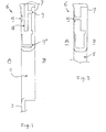
- Fig. 1 schematically shows, in a cross-sectional view, a first embodiment of a container handle according to the present invention.
- Fig. 2 schematically shows, in top view, part of the embodiment of Fig. 1.
- Fig. 3 schematically shows, in a cross-sectional view, a second embodiment of a container handle according to the present invention.
- Fig. 4 schematically shows, in front view, the embodiment of Figs. 1 and 3.
- Fig. 5 schematically shows, in side view, a third embodiment of a container handle according to the present invention.
- Fig. 6 schematically shows, in perspective, a container provided with handles according to the present invention.
-
- The
handle section 6 shown merely by way of non-limiting example in Fig. 1 is arranged above ahandle opening 5 in theside wall 3 of a container having an outside A and an inside B. Although a handle arranged in a side wall is shown, the present invention also relates to other handles, such as central handles of crates and similar containers. A container in which the present handle section may be used is shown in Fig. 6. - The
handle section 6 shown in Fig. 1 is integral with theside wall 3. This is, however, not essential and separately produced handles can also be envisaged. Thehandle section 6 is provided with alayer 7 of relatively soft material, preferably a thermoplastic material. In the embodiment shown, thegripping layer 7 is arranged on both sides of the handle section, the layer facing the inside B of the container extending further than the layer on the opposite side of the handle section. - In accordance with the present invention, a
cavity 18 is formed in thehandle section 6. Thecavity 18 is substantially centrally located and is, in the embodiment shown, open at the top surface of the handle section, thus having an approximate U-shape. It should be noted that other embodiments are possible in which the cavity is open towards the bottom surface of the handle section, that is, towards thehandle opening 5, thus forming an approximate inverse U-shape. It can also be envisaged that the cavity is open to one side. - In the embodiment shown, the
cavity 18 is filled with the same material as thegripping layer 7. An upper through-hole 9 constitutes an anchoring hole through which thematerial 7 in thecavity 18 is connected to thematerial 7 at the side of thehandle section 6. A lower through-hole 9' also constitutes an anchoring hole and connects the layers at the opposite sides of thehandle section 6. The through-holes 9 and 9' also serve to distribute the material of thegripping layer 7 during the manufacture thereof. - As can be seen, the width of the walls of the
cavity 18 is much less than the width of the entire handle section, resulting in significantly reduced cooling times and shrinkage problems during the manufacture of the container. The relativelysoft material 7 may be co-moulded but is preferably injection moulded in a separate mould, soon after the moulding of the container itself. - As shown in the top view of Fig. 2, the walls of the
cavity 18 are preferably connected by connectingelements 25. Such connection elements, which preferably are integral with the walls of the cavity, greatly increase the overall strength of the handle section. - According to a further aspect of the present invention, further through-holes are provided through which the
material 7 extends. As shown in Fig. 1, aview hole 19 is provided in the front face (facing the outside A) of thehandle section 6. Thisview hole 19 allows thematerial 7 to be visible at the front of the handle section. If the material of thegripping layer 7 has a colour which is different from the material of the container, thematerial 7 in theview hole 19 is clearly visible from the outside of the container. The view hole may form a discernible indication, such as a sign or symbol. Advantageously, theview hole 19 constitutes an alphanumeric character. This allows a name or type indication to be displayed, for example the name of a brewery of manufacturer, and/or an indication of the type or quantity of the product carried in the container. This is shown in Fig. 4 where the initials of a manufacturer are displayed by thematerial 7 in the view holes 19. - Returning to Fig. 1, it can be seen that the
view hole 19 widens towards the front of thehandle section 6. Although this is advantageous, it is not essential and view holes having a substantially uniform diameter can also be envisaged. However, widening theview hole 19 towards the front of the handle section has the advantage that a smaller amount of the relativeexpensive material 7 is needed. Also, to provide several view holes 19 having different shapes at the front of the handle section, a series of substantially uniform channels can be provided which extend into widened sections having different shapes. - As shown in Fig. 3, the provision of a cavity (18 in Fig. 1) is not necessary for providing view holes 19. The advantages of view holes 19, as discussed above and illustrated in Fig. 4, can therefore be obtained without the presence of such a cavity. In the embodiment of Fig. 3, the
view hole 19 is a through-hole which extends from the back of the handle section 6 (where agripping layer 7 is present) to the front of the same. Such a through hole both provides anchoring of the gripping layer and assists in the moulding of thegripping layer material 7. However, aview hole 19 is not necessarily connected with other parts of the gripping material via a through hole, cavity or channel. - As in the embodiment of Fig. 1, the
material 7 may slightly protrude from the view hole(s) 19 but is preferably substantially flush with the front of the handle section. - In the embodiment of Fig. 5 some of the view holes 19 have been modified so as to form ribs of
material 7. These ribs may protrude slightly to provide a better grip, or may be substantially flush with the handle section 6'. Other view holes 19 form an indication, such as the number of bottles in a crate and the content of each bottle, for example "24 x 25 cl.". - Although such an indication may be formed by gripping layer material having substantially the same colour as the handle or the entire crate, it is preferred that the gripping layer material has a different colour, advantageously a contrasting colour. In a grey or dark blue handle, for example, white or yellow markings provide a good contrast and improve the legibility of the indication.
- In this way the handle may be provided with indicia, such as the brand of the product carried in the container and/or the type of packaging of the product. In the latter case, the handle of a beer crate could, for example, read "24x0.5", indicating that 24 bottles of 0.5 litres may be carried in this container. These indicia are according to the present invention preferably provided by (relatively soft) gripping layer material, although other materials may also be used. For example, indicia could be provided in the handle of a crate using HDPE having two different colours. Thus the indications could be provided using a relatively hard material.
- The handle section 6' of Fig. 5 may contain a cavity (18 in Fig. 1) but this is not essential. It is noted that the handle section 6' is designed for use as a central handle in, for example, a crate. The ribs of
material 7 may, of course, also be applied in side wall handle sections as discussed above with reference to Figs. 1 and 3. The said "ribs" are not necessarily elongate and may also be round, square or have any other suitable shape. - The central handle section may be attached to a container using an attachment device as described in British Patent Application No. 0229184.7 filed 16 December 2002 and corresponding European Patent Application No. 03............. [P036 EP1] filed 16 December 2003, or any other suitable attachment device. Alternatively, the central handle section 6' may be integral with the container.
- According to an additional aspect of the present invention recesses 26 are provided on the handle section 6' to receive the thumb (or any other finger) of the user of the container.
Recesses 26 facilitate the lifting and carrying of the container. Although therecesses 26 are shown to be located near the respective ends of the handle section 6', they could also be located further away from the ends. Instead of tworecesses 26, a single recess or a plurality of recesses could be provided. - The exemplary crate 1 of Fig. 6 comprises a
base 2 andside walls 3 which extend substantially perpendicularly from thebase 2. The upper edges of thewalls 3 define a rim 4. Handlesections 6 are defined by grippingopenings 5 and are provided with agripping layer 7 of a relatively soft material, for example SEBS (styrene ethylene butadyene styrene) or any suitable thermoplastic material. The crate 1 is preferably made of HDPE (high density polyethylene) or another suitable plastics material. Theside walls 3 are preferably integral with thebase 2, although the crate 1 could be assembled from separate components. Instead of substantiallyperpendicular side walls 3, slanting side walls could be envisaged. - The
gripping layer 7 may provide indicia or indications in accordance with the present invention. Alternatively, or additionally, thehandle section 6 may be hollow, having a U-shaped cross-section in accordance with the present invention. - It will therefore be understood by those skilled in the art that the present invention is not limited to the embodiments illustrated above and that many modifications and additions may be made without departing from the scope of the invention as defined in the appending claims.
Claims (13)
- A container (1) for storing and/or transporting objects, the container being made of a plastics material and comprising a base (2) extending in a first direction and at least two side walls (3) extending from the base in a second direction, the container being provided with at least one handle section (6) provided at least partially with a gripping layer (7) made out of a material having a smaller hardness than said plastics material, wherein the handle section (6) is provided with at least one view hole (19) through which the material of the gripping layer (7) is visible from the outside the handle section, and wherein the at least one view hole (19) is shaped so as to form a discernible indication.
- The container according to claim 1, wherein the indication constitutes at least one alphanumeric character.
- The container according to claim 2, wherein a plurality of view holes (19) form a name, such as a brand or type name.
- The container according to any of claims 1-3, wherein at least some view holes (19) are shaped to form gripping ribs.
- A container (1) for storing and/or transporting objects, the container being made of a plastics material and comprising a base (2) extending in a first direction and at least two side walls (3) extending from the base in a second direction, the container being provided with at least one handle section (6) covered at least partially by a gripping layer (7) made out of a material having a smaller hardness than said plastics material, wherein the handle section (6) is substantially U-shaped so as to provide a cavity (18).
- The container according to claim 5, wherein the cavity (18) is filled with the thermoplastic material constituting the gripping layer (7).
- The container according to claim 5 or 6, wherein the cavity (18) faces upward.
- The container according to claim 5 or 6, wherein the cavity (18) faces downward.
- The container according to any of claims 5-8, wherein the cavity (18) is provided with at least one connecting element (25) with connects opposing walls of the cavity, said connecting element preferably being integral with said walls.
- The container according to any of claims 5-9, wherein the handle section (6) is provided with at least one through-hole (9, 19) through which the material of the gripping layer (7) may extend.
- The container according to claim 10, wherein the at least one through-hole is a view hole (19) through which the material of the gripping layer (7) is visible from outside the handle section.
- The container according to any of the preceding claims, wherein the handle section (6, 6') is provided with recesses (26) for receiving a thumb of a user.
- A handle (6, 6') for use in a container according to any of the preceding claims.
Applications Claiming Priority (4)
| Application Number | Priority Date | Filing Date | Title |
|---|---|---|---|
| GB0229184 | 2002-12-16 | ||
| GB0229184A GB2396346A (en) | 2002-12-16 | 2002-12-16 | Container handle |
| GB0302387A GB0302387D0 (en) | 2003-02-03 | 2003-02-03 | A container having at least one handle |
| GB0302387 | 2003-02-03 |
Publications (3)
| Publication Number | Publication Date |
|---|---|
| EP1431193A2 true EP1431193A2 (en) | 2004-06-23 |
| EP1431193A3 EP1431193A3 (en) | 2004-09-01 |
| EP1431193B1 EP1431193B1 (en) | 2013-03-13 |
Family
ID=32395889
Family Applications (1)
| Application Number | Title | Priority Date | Filing Date |
|---|---|---|---|
| EP20030078892 Expired - Lifetime EP1431193B1 (en) | 2002-12-16 | 2003-12-16 | Container handles |
Country Status (4)
| Country | Link |
|---|---|
| EP (1) | EP1431193B1 (en) |
| DK (1) | DK1431193T3 (en) |
| ES (1) | ES2408250T3 (en) |
| PT (1) | PT1431193E (en) |
Cited By (5)
| Publication number | Priority date | Publication date | Assignee | Title |
|---|---|---|---|---|
| EP1707493A1 (en) * | 2005-04-01 | 2006-10-04 | D W Plastics N.V. | Coloured plastic crate |
| WO2008128682A1 (en) * | 2007-04-18 | 2008-10-30 | Schoeller Arca Systems Gmbh | Relief overmolding |
| EP3012082A1 (en) * | 2014-10-02 | 2016-04-27 | Schoeller Allibert GmbH | Bottle crate in two component construction |
| USD866973S1 (en) * | 2014-01-28 | 2019-11-19 | Interdesign, Inc. | Bin |
| US10675833B2 (en) * | 2015-04-13 | 2020-06-09 | Keter Plastic Ltd. | Multilayered injection molded interlace-like article and method for molding same |
Citations (7)
| Publication number | Priority date | Publication date | Assignee | Title |
|---|---|---|---|---|
| US3454439A (en) * | 1966-03-16 | 1969-07-08 | Phillips Petroleum Co | Method of making an article carrying case |
| EP0260698A1 (en) * | 1986-09-18 | 1988-03-23 | Schoeller-Plast AG | Receptacle hand grip, especially for crates |
| EP0464894A1 (en) * | 1990-06-22 | 1992-01-08 | Heineken Technical Services B.V. | Crate for accommodating a plurality of bottles |
| DE4022884A1 (en) * | 1990-07-18 | 1992-01-23 | Schoeller Plast Ag | Plastic bottle crate - has handle core and outer portion with different degrees of hardness |
| US5799369A (en) * | 1995-04-07 | 1998-09-01 | Leifheit Ag | Utensil handle |
| EP1000865A1 (en) * | 1998-10-22 | 2000-05-17 | D.W. PLASTICS, naamloze vennootschap | Crate made of plastic, provided with at least one handle |
| NL1010724C2 (en) * | 1998-12-04 | 2000-06-06 | Wavin Trepak B V | Double walled crate for bottles is made from injection molded plastic and has softened handgrips to minimize discomfort for user |
-
2003
- 2003-12-16 PT PT03078892T patent/PT1431193E/en unknown
- 2003-12-16 DK DK03078892T patent/DK1431193T3/en active
- 2003-12-16 ES ES03078892T patent/ES2408250T3/en not_active Expired - Lifetime
- 2003-12-16 EP EP20030078892 patent/EP1431193B1/en not_active Expired - Lifetime
Patent Citations (7)
| Publication number | Priority date | Publication date | Assignee | Title |
|---|---|---|---|---|
| US3454439A (en) * | 1966-03-16 | 1969-07-08 | Phillips Petroleum Co | Method of making an article carrying case |
| EP0260698A1 (en) * | 1986-09-18 | 1988-03-23 | Schoeller-Plast AG | Receptacle hand grip, especially for crates |
| EP0464894A1 (en) * | 1990-06-22 | 1992-01-08 | Heineken Technical Services B.V. | Crate for accommodating a plurality of bottles |
| DE4022884A1 (en) * | 1990-07-18 | 1992-01-23 | Schoeller Plast Ag | Plastic bottle crate - has handle core and outer portion with different degrees of hardness |
| US5799369A (en) * | 1995-04-07 | 1998-09-01 | Leifheit Ag | Utensil handle |
| EP1000865A1 (en) * | 1998-10-22 | 2000-05-17 | D.W. PLASTICS, naamloze vennootschap | Crate made of plastic, provided with at least one handle |
| NL1010724C2 (en) * | 1998-12-04 | 2000-06-06 | Wavin Trepak B V | Double walled crate for bottles is made from injection molded plastic and has softened handgrips to minimize discomfort for user |
Cited By (5)
| Publication number | Priority date | Publication date | Assignee | Title |
|---|---|---|---|---|
| EP1707493A1 (en) * | 2005-04-01 | 2006-10-04 | D W Plastics N.V. | Coloured plastic crate |
| WO2008128682A1 (en) * | 2007-04-18 | 2008-10-30 | Schoeller Arca Systems Gmbh | Relief overmolding |
| USD866973S1 (en) * | 2014-01-28 | 2019-11-19 | Interdesign, Inc. | Bin |
| EP3012082A1 (en) * | 2014-10-02 | 2016-04-27 | Schoeller Allibert GmbH | Bottle crate in two component construction |
| US10675833B2 (en) * | 2015-04-13 | 2020-06-09 | Keter Plastic Ltd. | Multilayered injection molded interlace-like article and method for molding same |
Also Published As
| Publication number | Publication date |
|---|---|
| EP1431193A3 (en) | 2004-09-01 |
| ES2408250T3 (en) | 2013-06-19 |
| PT1431193E (en) | 2013-05-07 |
| EP1431193B1 (en) | 2013-03-13 |
| DK1431193T3 (en) | 2013-06-10 |
Similar Documents
| Publication | Publication Date | Title |
|---|---|---|
| CA2778711C (en) | Beverage can marketing device | |
| US8002133B2 (en) | Colorant container | |
| EP2074036B1 (en) | Channel features for pressurized bottle | |
| US9956815B2 (en) | Overmolded cutlery articles | |
| MXPA01013221A (en) | Container. | |
| CA2280801A1 (en) | Injection moulding process and apparatus for making articles from two components | |
| EP1431193B1 (en) | Container handles | |
| US10071840B2 (en) | Cap for closing the neck finish of a container and method for manufacturing said cap | |
| WO2016209739A1 (en) | Overmolded low cost cutlery | |
| EP0770470A1 (en) | Blow molded plastic container and method for producing the same | |
| US20100107341A1 (en) | Single Container Type for Multiple Fabric Care Products | |
| CA2377613C (en) | Spigot assembly for container | |
| US20060123677A1 (en) | Container and method for making same | |
| EP2296986B1 (en) | Method of providing a container with markings | |
| EP1595799B1 (en) | A container provided with markings | |
| WO2006034247A2 (en) | Ruler with rubber/plastic composition | |
| US20050045657A1 (en) | Squeeze bottle | |
| JP4647971B2 (en) | Sandwich moldings | |
| US20030047484A1 (en) | Product packaging with display | |
| EP3028833B1 (en) | Handle manufacturing method, system and mold for manufacturing same | |
| ITBZ960011U1 (en) | FOOD CONTAINER. | |
| AU2022263485A1 (en) | Pressure containers and pressure container assortment | |
| KR100846407B1 (en) | Toy article | |
| JP3949376B2 (en) | Tube container | |
| JP3090027U (en) | Dummy body for vending machines for container beverages |
Legal Events
| Date | Code | Title | Description |
|---|---|---|---|
| PUAI | Public reference made under article 153(3) epc to a published international application that has entered the european phase |
Free format text: ORIGINAL CODE: 0009012 |
|
| AK | Designated contracting states |
Kind code of ref document: A2 Designated state(s): AT BE BG CH CY CZ DE DK EE ES FI FR GB GR HU IE IT LI LU MC NL PT RO SE SI SK TR |
|
| AX | Request for extension of the european patent |
Extension state: AL LT LV MK |
|
| PUAL | Search report despatched |
Free format text: ORIGINAL CODE: 0009013 |
|
| AK | Designated contracting states |
Kind code of ref document: A3 Designated state(s): AT BE BG CH CY CZ DE DK EE ES FI FR GB GR HU IE IT LI LU MC NL PT RO SE SI SK TR |
|
| AX | Request for extension of the european patent |
Extension state: AL LT LV MK |
|
| 17P | Request for examination filed |
Effective date: 20050301 |
|
| AKX | Designation fees paid |
Designated state(s): AT BE BG CH CY CZ DE DK EE ES FI FR GB GR HU IE IT LI LU MC NL PT RO SE SI SK TR |
|
| 17Q | First examination report despatched |
Effective date: 20090804 |
|
| GRAP | Despatch of communication of intention to grant a patent |
Free format text: ORIGINAL CODE: EPIDOSNIGR1 |
|
| GRAS | Grant fee paid |
Free format text: ORIGINAL CODE: EPIDOSNIGR3 |
|
| GRAA | (expected) grant |
Free format text: ORIGINAL CODE: 0009210 |
|
| AK | Designated contracting states |
Kind code of ref document: B1 Designated state(s): AT BE BG CH CY CZ DE DK EE ES FI FR GB GR HU IE IT LI LU MC NL PT RO SE SI SK TR |
|
| REG | Reference to a national code |
Ref country code: GB Ref legal event code: FG4D |
|
| REG | Reference to a national code |
Ref country code: CH Ref legal event code: EP Ref country code: AT Ref legal event code: REF Ref document number: 600651 Country of ref document: AT Kind code of ref document: T Effective date: 20130315 |
|
| REG | Reference to a national code |
Ref country code: IE Ref legal event code: FG4D |
|
| REG | Reference to a national code |
Ref country code: DE Ref legal event code: R082 Ref document number: 60343491 Country of ref document: DE Representative=s name: RECHTS- UND PATENTANWAELTE LORENZ SEIDLER GOSS, DE Ref country code: PT Ref legal event code: SC4A Free format text: AVAILABILITY OF NATIONAL TRANSLATION Effective date: 20130429 Ref country code: DE Ref legal event code: R082 Ref document number: 60343491 Country of ref document: DE Representative=s name: LORENZ SEIDLER GOSSEL RECHTSANWAELTE PATENTANW, DE |
|
| REG | Reference to a national code |
Ref country code: DE Ref legal event code: R096 Ref document number: 60343491 Country of ref document: DE Effective date: 20130508 |
|
| REG | Reference to a national code |
Ref country code: CH Ref legal event code: NV Representative=s name: CRONIN INTELLECTUAL PROPERTY, CH |
|
| REG | Reference to a national code |
Ref country code: DK Ref legal event code: T3 |
|
| REG | Reference to a national code |
Ref country code: ES Ref legal event code: FG2A Ref document number: 2408250 Country of ref document: ES Kind code of ref document: T3 Effective date: 20130619 |
|
| PG25 | Lapsed in a contracting state [announced via postgrant information from national office to epo] |
Ref country code: BG Free format text: LAPSE BECAUSE OF FAILURE TO SUBMIT A TRANSLATION OF THE DESCRIPTION OR TO PAY THE FEE WITHIN THE PRESCRIBED TIME-LIMIT Effective date: 20130613 Ref country code: SE Free format text: LAPSE BECAUSE OF FAILURE TO SUBMIT A TRANSLATION OF THE DESCRIPTION OR TO PAY THE FEE WITHIN THE PRESCRIBED TIME-LIMIT Effective date: 20130313 |
|
| REG | Reference to a national code |
Ref country code: NL Ref legal event code: T3 |
|
| REG | Reference to a national code |
Ref country code: SK Ref legal event code: T3 Ref document number: E 14091 Country of ref document: SK |
|
| PG25 | Lapsed in a contracting state [announced via postgrant information from national office to epo] |
Ref country code: FI Free format text: LAPSE BECAUSE OF FAILURE TO SUBMIT A TRANSLATION OF THE DESCRIPTION OR TO PAY THE FEE WITHIN THE PRESCRIBED TIME-LIMIT Effective date: 20130313 Ref country code: SI Free format text: LAPSE BECAUSE OF FAILURE TO SUBMIT A TRANSLATION OF THE DESCRIPTION OR TO PAY THE FEE WITHIN THE PRESCRIBED TIME-LIMIT Effective date: 20130313 Ref country code: GR Free format text: LAPSE BECAUSE OF FAILURE TO SUBMIT A TRANSLATION OF THE DESCRIPTION OR TO PAY THE FEE WITHIN THE PRESCRIBED TIME-LIMIT Effective date: 20130614 |
|
| PG25 | Lapsed in a contracting state [announced via postgrant information from national office to epo] |
Ref country code: RO Free format text: LAPSE BECAUSE OF FAILURE TO SUBMIT A TRANSLATION OF THE DESCRIPTION OR TO PAY THE FEE WITHIN THE PRESCRIBED TIME-LIMIT Effective date: 20130313 Ref country code: EE Free format text: LAPSE BECAUSE OF FAILURE TO SUBMIT A TRANSLATION OF THE DESCRIPTION OR TO PAY THE FEE WITHIN THE PRESCRIBED TIME-LIMIT Effective date: 20130313 |
|
| PG25 | Lapsed in a contracting state [announced via postgrant information from national office to epo] |
Ref country code: CY Free format text: LAPSE BECAUSE OF FAILURE TO SUBMIT A TRANSLATION OF THE DESCRIPTION OR TO PAY THE FEE WITHIN THE PRESCRIBED TIME-LIMIT Effective date: 20130313 |
|
| PLBE | No opposition filed within time limit |
Free format text: ORIGINAL CODE: 0009261 |
|
| STAA | Information on the status of an ep patent application or granted ep patent |
Free format text: STATUS: NO OPPOSITION FILED WITHIN TIME LIMIT |
|
| 26N | No opposition filed |
Effective date: 20131216 |
|
| PG25 | Lapsed in a contracting state [announced via postgrant information from national office to epo] |
Ref country code: IT Free format text: LAPSE BECAUSE OF FAILURE TO SUBMIT A TRANSLATION OF THE DESCRIPTION OR TO PAY THE FEE WITHIN THE PRESCRIBED TIME-LIMIT Effective date: 20130313 |
|
| REG | Reference to a national code |
Ref country code: DE Ref legal event code: R097 Ref document number: 60343491 Country of ref document: DE Effective date: 20131216 |
|
| REG | Reference to a national code |
Ref country code: HU Ref legal event code: AG4A Ref document number: E018878 Country of ref document: HU |
|
| GBPC | Gb: european patent ceased through non-payment of renewal fee |
Effective date: 20131216 |
|
| PG25 | Lapsed in a contracting state [announced via postgrant information from national office to epo] |
Ref country code: MC Free format text: LAPSE BECAUSE OF FAILURE TO SUBMIT A TRANSLATION OF THE DESCRIPTION OR TO PAY THE FEE WITHIN THE PRESCRIBED TIME-LIMIT Effective date: 20130313 |
|
| REG | Reference to a national code |
Ref country code: IE Ref legal event code: MM4A |
|
| PG25 | Lapsed in a contracting state [announced via postgrant information from national office to epo] |
Ref country code: IE Free format text: LAPSE BECAUSE OF NON-PAYMENT OF DUE FEES Effective date: 20131216 |
|
| PG25 | Lapsed in a contracting state [announced via postgrant information from national office to epo] |
Ref country code: GB Free format text: LAPSE BECAUSE OF NON-PAYMENT OF DUE FEES Effective date: 20131216 |
|
| PG25 | Lapsed in a contracting state [announced via postgrant information from national office to epo] |
Ref country code: TR Free format text: LAPSE BECAUSE OF FAILURE TO SUBMIT A TRANSLATION OF THE DESCRIPTION OR TO PAY THE FEE WITHIN THE PRESCRIBED TIME-LIMIT Effective date: 20130313 |
|
| REG | Reference to a national code |
Ref country code: FR Ref legal event code: PLFP Year of fee payment: 13 |
|
| REG | Reference to a national code |
Ref country code: FR Ref legal event code: PLFP Year of fee payment: 14 |
|
| PGFP | Annual fee paid to national office [announced via postgrant information from national office to epo] |
Ref country code: LU Payment date: 20161227 Year of fee payment: 14 Ref country code: CH Payment date: 20161128 Year of fee payment: 14 Ref country code: DK Payment date: 20161208 Year of fee payment: 14 |
|
| PGFP | Annual fee paid to national office [announced via postgrant information from national office to epo] |
Ref country code: PT Payment date: 20161118 Year of fee payment: 14 Ref country code: ES Payment date: 20161130 Year of fee payment: 14 Ref country code: FR Payment date: 20161207 Year of fee payment: 14 |
|
| PGFP | Annual fee paid to national office [announced via postgrant information from national office to epo] |
Ref country code: SK Payment date: 20171215 Year of fee payment: 15 Ref country code: HU Payment date: 20171212 Year of fee payment: 15 Ref country code: CZ Payment date: 20171215 Year of fee payment: 15 Ref country code: NL Payment date: 20171221 Year of fee payment: 15 |
|
| PGFP | Annual fee paid to national office [announced via postgrant information from national office to epo] |
Ref country code: BE Payment date: 20171219 Year of fee payment: 15 Ref country code: AT Payment date: 20171228 Year of fee payment: 15 |
|
| PGFP | Annual fee paid to national office [announced via postgrant information from national office to epo] |
Ref country code: DE Payment date: 20180228 Year of fee payment: 15 |
|
| REG | Reference to a national code |
Ref country code: CH Ref legal event code: PCAR Free format text: NEW ADDRESS: CHEMIN DE LA VUARPILLIERE 29, 1260 NYON (CH) |
|
| REG | Reference to a national code |
Ref country code: DK Ref legal event code: EBP Effective date: 20171231 |
|
| PG25 | Lapsed in a contracting state [announced via postgrant information from national office to epo] |
Ref country code: PT Free format text: LAPSE BECAUSE OF NON-PAYMENT OF DUE FEES Effective date: 20180618 |
|
| REG | Reference to a national code |
Ref country code: CH Ref legal event code: PL |
|
| PG25 | Lapsed in a contracting state [announced via postgrant information from national office to epo] |
Ref country code: LU Free format text: LAPSE BECAUSE OF NON-PAYMENT OF DUE FEES Effective date: 20171216 |
|
| REG | Reference to a national code |
Ref country code: FR Ref legal event code: ST Effective date: 20180831 |
|
| PG25 | Lapsed in a contracting state [announced via postgrant information from national office to epo] |
Ref country code: FR Free format text: LAPSE BECAUSE OF NON-PAYMENT OF DUE FEES Effective date: 20180102 |
|
| PG25 | Lapsed in a contracting state [announced via postgrant information from national office to epo] |
Ref country code: LI Free format text: LAPSE BECAUSE OF NON-PAYMENT OF DUE FEES Effective date: 20171231 Ref country code: CH Free format text: LAPSE BECAUSE OF NON-PAYMENT OF DUE FEES Effective date: 20171231 |
|
| PG25 | Lapsed in a contracting state [announced via postgrant information from national office to epo] |
Ref country code: DK Free format text: LAPSE BECAUSE OF NON-PAYMENT OF DUE FEES Effective date: 20171231 |
|
| REG | Reference to a national code |
Ref country code: DE Ref legal event code: R119 Ref document number: 60343491 Country of ref document: DE |
|
| REG | Reference to a national code |
Ref country code: ES Ref legal event code: FD2A Effective date: 20190703 |
|
| PG25 | Lapsed in a contracting state [announced via postgrant information from national office to epo] |
Ref country code: CZ Free format text: LAPSE BECAUSE OF NON-PAYMENT OF DUE FEES Effective date: 20181216 Ref country code: ES Free format text: LAPSE BECAUSE OF NON-PAYMENT OF DUE FEES Effective date: 20171217 |
|
| REG | Reference to a national code |
Ref country code: NL Ref legal event code: MM Effective date: 20190101 |
|
| REG | Reference to a national code |
Ref country code: AT Ref legal event code: MM01 Ref document number: 600651 Country of ref document: AT Kind code of ref document: T Effective date: 20181216 |
|
| REG | Reference to a national code |
Ref country code: SK Ref legal event code: MM4A Ref document number: E 14091 Country of ref document: SK Effective date: 20181216 |
|
| PG25 | Lapsed in a contracting state [announced via postgrant information from national office to epo] |
Ref country code: NL Free format text: LAPSE BECAUSE OF NON-PAYMENT OF DUE FEES Effective date: 20190101 |
|
| REG | Reference to a national code |
Ref country code: BE Ref legal event code: MM Effective date: 20181231 |
|
| PG25 | Lapsed in a contracting state [announced via postgrant information from national office to epo] |
Ref country code: SK Free format text: LAPSE BECAUSE OF NON-PAYMENT OF DUE FEES Effective date: 20181216 Ref country code: DE Free format text: LAPSE BECAUSE OF NON-PAYMENT OF DUE FEES Effective date: 20190702 |
|
| PG25 | Lapsed in a contracting state [announced via postgrant information from national office to epo] |
Ref country code: HU Free format text: LAPSE BECAUSE OF NON-PAYMENT OF DUE FEES Effective date: 20181217 Ref country code: BE Free format text: LAPSE BECAUSE OF NON-PAYMENT OF DUE FEES Effective date: 20181231 |
|
| PG25 | Lapsed in a contracting state [announced via postgrant information from national office to epo] |
Ref country code: AT Free format text: LAPSE BECAUSE OF NON-PAYMENT OF DUE FEES Effective date: 20181216 |