EP1431138A1 - Guide device for automobile seatbelt - Google Patents
Guide device for automobile seatbelt Download PDFInfo
- Publication number
- EP1431138A1 EP1431138A1 EP03029008A EP03029008A EP1431138A1 EP 1431138 A1 EP1431138 A1 EP 1431138A1 EP 03029008 A EP03029008 A EP 03029008A EP 03029008 A EP03029008 A EP 03029008A EP 1431138 A1 EP1431138 A1 EP 1431138A1
- Authority
- EP
- European Patent Office
- Prior art keywords
- rod
- seatbelt
- vehicle body
- secured
- guide portion
- Prior art date
- Legal status (The legal status is an assumption and is not a legal conclusion. Google has not performed a legal analysis and makes no representation as to the accuracy of the status listed.)
- Granted
Links
- 230000000452 restraining effect Effects 0.000 claims description 2
- 239000002184 metal Substances 0.000 description 6
- 230000002787 reinforcement Effects 0.000 description 5
- 238000005452 bending Methods 0.000 description 4
- 230000003449 preventive effect Effects 0.000 description 4
- 230000009467 reduction Effects 0.000 description 3
- 239000011347 resin Substances 0.000 description 3
- 229920005989 resin Polymers 0.000 description 3
- 238000003466 welding Methods 0.000 description 3
- 238000000605 extraction Methods 0.000 description 2
- 238000005242 forging Methods 0.000 description 2
- 239000011521 glass Substances 0.000 description 2
- 239000000463 material Substances 0.000 description 2
- 238000000465 moulding Methods 0.000 description 2
- 238000004804 winding Methods 0.000 description 2
- 230000008878 coupling Effects 0.000 description 1
- 238000010168 coupling process Methods 0.000 description 1
- 238000005859 coupling reaction Methods 0.000 description 1
- 230000006872 improvement Effects 0.000 description 1
- 230000007246 mechanism Effects 0.000 description 1
- 230000004048 modification Effects 0.000 description 1
- 238000012986 modification Methods 0.000 description 1
- 230000003014 reinforcing effect Effects 0.000 description 1
Images





Classifications
-
- B—PERFORMING OPERATIONS; TRANSPORTING
- B60—VEHICLES IN GENERAL
- B60R—VEHICLES, VEHICLE FITTINGS, OR VEHICLE PARTS, NOT OTHERWISE PROVIDED FOR
- B60R22/00—Safety belts or body harnesses in vehicles
- B60R22/18—Anchoring devices
- B60R22/24—Anchoring devices secured to the side, door, or roof of the vehicle
-
- B—PERFORMING OPERATIONS; TRANSPORTING
- B60—VEHICLES IN GENERAL
- B60R—VEHICLES, VEHICLE FITTINGS, OR VEHICLE PARTS, NOT OTHERWISE PROVIDED FOR
- B60R22/00—Safety belts or body harnesses in vehicles
- B60R22/18—Anchoring devices
- B60R2022/1818—Belt guides
Definitions
- the present invention relates to a guide device of an automobile seatbelt for guiding a seatbelt drawn out from a retractor.
- a shoulder belt which is used in station wagons and the like to hold the chest of the passenger, is arranged such that a seatbelt (shoulder belt) 21 drawn out from a retractor 20 is attached by folding back with a sash guide stay 23 across a rear quarter glass 22.
- this type of the sash guide stay 23 is disclosed as a shoulder anchor for a vertically adjusting mechanism in Japanese Unexamined Utility Model Application Publication No. 7-13619, it is not necessarily preferable for outside appearance because it is exposed to the side of a compartment.
- Japanese Unexamined Patent Application Publication No. 11-198755 discloses a seatbelt guide (guide device) disposed at a center portion of a rear tray although it is installed for a sedan type, and when this seatbelt guide is installed in the station wagon in the same manner, the good appearance of the compartment of the station wagon can be attained.
- an object of the present invention is to provide a guide device for an automobile seatbelt capable of reducing a cost by realizing the reduction in size and weight of the guide device as well as capable of improving a design freedom of a layout while securing a required strength.
- the seatbelt guide device for an automobile guides a seatbelt drawn out of a retractor and comprises a main rod having a guide portion formed thereto for suspending and folding back a seatbelt and folds back the seatbelt, and an auxiliary rod for dispersing a load applied to the main rod, and the main rod and the auxiliary rod are restrained each other and secured to a vehicle body.
- reference numeral 1 denotes a rear quarter trim disposed behind a rear seat of an automobile (not shown), and a known retractor 3 is disposed in the rear quarter trim 1 to wind a base end of a seatbelt 2 (shoulder belt) and to accommodate the seatbelt 2 into the rear quarter trim 1.
- the seatbelt 2 drawn out of the retractor 3 is guided through a seatbelt guide device 4 disposed in the rear quarter trim 1, extended from a belt extract unit 6 which is disposed on the rear quarter trim 1 at the lower end of a rear quarter glass 5, and coupled with a waist belt through a tongue (not shown).
- the seatbelt guide device 4 has a structure by combining a small bracket fixedly secured to a vehicle body and a rod, and has a required strength while reducing its weight.
- the seatbelt guide device 4 has a function for folding back the seatbelt 2 drawn out of the retractor 3 as well as reducing a load applied to the vehicle body by dispersing the load transmitted from the seatbelt 2.
- the seatbelt guide device 4 comprises mainly brackets 7, 8, 9 and rods 10, 11, 12.
- Each of the brackets 7, 8, 9 is formed by a sheet metal and secured to the vehicle body by bolts (not shown), and each of the rods 10, 11, 12 is formed by bending a metal rod member having a predetermined diameter.
- the respective rods 10, 11, 12, 13 are fixedly secured to the brackets 7, 8, 9 by welding and the like and restrained each other (except the rod 12 as described below) to secure a required strength.
- the rod 10 corresponds to a first rod of the present invention
- the rod 11 corresponds to a third rod of the present invention
- the rod 13 corresponds to a second rod of the present invention.
- a bracket 7 side shows the upper direction of the vehicle body
- a bracket 9 side shows the front side thereof.
- the bracket 7 is a slender bracket having holes, which are formed at both ends thereof and through which the bracket 7 is attached to the vehicle body, and a rib-shaped bent portion formed at approximately the center thereof. An end portion of the rod 10 is fixedly secured to the bent portion, and the end portion of the rod 11 is fixedly secured to the bracket 7 in the vicinity of the rod 10.
- the rod 10 is a main rod constituting the main portion of the seatbelt guide device 4 and has an arc-shaped webbing guide portion 10a formed thereto.
- the webbing guide portion 10a is formed by bending the metal rod member and folds back and guides the seatbelt 2.
- the end portion of the webbing guide portion 10a is fixedly secured to the bracket 7, and the base end of the rod-shaped straight portion thereof is secured to the bracket 8.
- the rod 11 is also formed by bending the straight metal rod member to a shape approximately similar to that of the webbing guide portion 10a.
- the end portion of the rod 11 is fixedly secured to the bracket 7, and the base end of the rod-shaped straight portion thereof is fixedly secured to the bracket 8 together with the rod 10.
- the bracket 7 is disposed to a portion (first portion) of the vehicle body facing the retractor 3 so that the webbing guide portion 10a of the rod 10 fixedly secured to the bracket 7 faces a desired belt folding back direction, and the straight portions of the rods 10 and 11 are extended in a direction obliquely intersecting the upper surface of the seatbelt 2.
- the base ends of both the rod 10 and 11 are supported by the bracket 8 which is attached to a portion (second portion) of the vehicle body between the bracket 7 and the retractor 3. That is, the rod 11 is an auxiliary member for dispersing the load applied to the rod 10 and suppressing the deformation of the bracket 7.
- the bracket 8 has two rib-shaped projections disposed approximately in parallel with each other on both the sides of an attachment hole defined approximately at the center of the bracket 8, through which it is attached to the vehicle body, and the base ends of the rods 10 and 11 are fixedly secured to the back surfaces of the respective projections. Further, a reinforcement member 14 formed of a thin sheet metal is wound around and fixedly secured to the straight portions of the rods 10 and 11 extending from the bracket 8 so that the rods 10 and 11 are prevented from falling down in an open direction by the reinforcement member 14 acting as a support member for coupling the rod 10 with the rod 11.
- the approximately L-shaped rod 12 is used to prevent the seatbelt 2 from being removed from the webbing guide portion 10a to the retractor 3 side.
- the rod 12 is disposed approximately in parallel with the bracket 7 with end portion thereof in a lateral direction fixedly secured to the outer periphery of the bent portion of the rod 10 located between the straight portion and the webbing guide portion 10a thereof (refer to FIG. 4), and the other end of the rod 12 is opened.
- the rod 12 is provided to prevent a removal of the seatbelt 2 from the webbing guide portion 10a as described above, it does not necessarily have the rod member, and the removal of the seatbelt 2 may be prevented by covering the webbing guide portion 10a with a resin cover and the like in place of the rod 12.
- the end portion of the rod 13 is abutted against and fixedly secured to the inside of the bent portion of the rod 10 located between the straight portion and the webbing guide portion 10a thereof (refer to FIG. 5), and the base end of the rod 13 is fixedly secured to the end of the bracket 9 (the end opposite of an attachment hole to the vehicle body) disposed to a portion (third portion) of the vehicle body in the vicinity of the bracket 8.
- the rod 13 is an auxiliary member for supporting the rod 10 from under the webbing guide portion 10a so as to prevent the rod 10 from falling down in the front direction of the vehicle body when a load is applied thereto.
- the portions of the rods 10, 11, 12, with which the seatbelt 2 comes into contact are covered with resin covers or coated with a resin material, thereby the winding property of the seatbelt 2 can be improved.
- the seatbelt 2 extract from the retractor 3 is extended from under the base portions of the rods 10 and 11 to the webbing guide portion 10a of the rod 10. Then, the seatbelt 2 is suspended and folded back in a predetermined direction by the webbing guide portion 10a, and extended from the belt extraction unit 6 of the rear quarter trim 1.
- the seatbelt 2 extended from the belt extraction unit 6 is combined with, for example, a waist seatbelt (not shown) and constitutes a three-point type seatbelt. With this arrangement, the chest of a passenger is securely held by the seatbelt 2 drawn out of the belt extract unit 6 as well as the waist of the passenger is held by the waist belt (not shown).
- the seatbelt 2 contacts the webbing guide portion 10a of the rod 10 and a load is applied thereto, the seatbelt 2 fits in the arc shape of the webbing guide portion 10a and is prevented from slipping down as well as the load is dispersed by the three rods 10, 11, 13. Accordingly, even if an impact acts on the seatbelt 2, since the impact is received by the rods 10, 11, 13 in a dispersed state, it is possible to prevent the concentration of the load due to the impact to the portions of the vehicle body through which the rods 10, 11, 13 are attached thereto. Accordingly, it does not necessarily provide large brackets with the vehicle body to attach the rods thereto.
- the load can be transmitted to the vehicle body under desirable optimum conditions which are set according to the restraining conditions of the respective rods in consideration of the load received from the seatbelt 2, the radii, the bent shapes, the materials and the span lengths of the respective rods 10, 11, 13, the positions of the vehicle body at which the rods are attached to the vehicle body, the shapes of the attachment positions, and the like.
- the load applied to the vehicle body can be reduced as well as a required strength can be secured also with respect to the vibration received from the vehicle body, thereby the durability of the rods 10, 11, 13 can be improved.
- the seatbelt guide device 4 in this embodiment is arranged by using the small and light brackets 7, 8, 9 formed of the sheet metal and the rods 10, 11, 12, 13 formed by bending the easily available rod member, the weight and the cost of parts can be reduced while securing the strength and a belt folding back function.
- FIG. 6 is a perspective view showing the arrangement of a seatbelt guide device according to the second embodiment of the present invention.
- the second embodiment simplifies the arrangement of the seatbelt guide device 4 of the first embodiment described above by omitting the rod 11 and the reinforcement member 14 used therein. That is, since the rod 11 is used to disperse the load applied to the rod 10 and the reinforcement member 14 is used to prevent the rods 10 and 11 from falling down in the open direction as described above, even if the rods 10 and 11 are omitted, the strength of the overall seatbelt guide device 4 is not largely affected thereby. Accordingly, a lighter and less expensive seatbelt guide device can be realized by omitting these rods.
- the seatbelt guide device 4A of the second embodiment comprises a bracket 8A, the brackets 7 and 9, and rods 10, 12 and 13 by omitting the rod 11 and the reinforcement member 14.
- the bracket 8A is a modification of the bracket 8 and has a smaller size than that of the bracket 8.
- the bracket 8A is formed in a shape obtained by removing the rib-shaped projection for securing the rod 11 from the bracket 8 of the first embodiment, and the relationship between the brackets 7, 8A, 9 and the rods 10, 12, 13 is approximately the same as that of the first embodiment except that the load from the seatbelt 2 is dispersed to the rods 10 and 13.
- the size of the bracket 8A can be made smaller than that of the bracket 8 in the first embodiment described above by omitting the rod 11 and the reinforcing member 14. Accordingly, not only the weight and the cost of the seatbelt guide device 4 can be more reduced but also the winding property of the seatbelt can be maintained in a good state even if a layout is such that the distance from a belt folding-back portion to the retractor 3 is short and the seatbelt 2 is twisted by reducing the number and the size of parts.
- FIG. 7 is a perspective view showing the arrangement of a seatbelt guide device 4B according to the third embodiment of the present invention.
- the number of parts is reduced by integrating the rod 12 with the rod 13. That is, the seatbelt guide device 4B of the third embodiment shown in FIG. 7 is provided with a rod 15 in place of the rod 13 used in the seatbelt guide device 4, and the end portion of the rod 15 is extended so that the end portion thereof also performs the function of the rod 12.
- the rod 15 is formed in an L-shape similar to that of the rod 12 by extending the end portion of the rod 13 that is fixedly secured to the inside of the bent portion of the rod 10 located between the straight portion and the webbing guide portion 10a thereof, and the L-shaped portion of the rod 15 forms an easy disconnection preventive portion 15a for preventing from unexpectedly removing the seatbelt 2 from the webbing guide portion 10a.
- the third embodiment can achieve a further cost reduction by more reducing the number of parts while maintaining an excellent operational easiness similar to that of the second embodiment because it is not necessary to separately provide the rod 12.
- the rod 15, which also performs the function of the rod 12 may be applied to the seatbelt guide device 4 of the first embodiment.
- FIG. 8 is the perspective view showing the arrangement of the seatbelt guide device according to the fourth embodiment of the present invention.
- FIG. 8 shows an example that the fourth embodiment is applied to the seatbelt guide device 4B of the third embodiment to eliminate the brackets 8A and 9.
- the seatbelt guide device 4C shown in FIG. 8 eliminates the bracket 8A by using a rod 16 of which base end is modified to permit the rod 16 to be directly fixed to the vehicle body in place of the rod 10 which is fixedly secured to the vehicle body through the bracket 8A. Further, the seatbelt guide device 4C eliminates the bracket 9 by using a rod 17 of which base end is modified to permit the rod 17 to be directly fixed to the vehicle body in place of the rod 15 which is fixedly secured to the vehicle body through the bracket 9.
- the rod 16 includes a webbing guide portion 16a and a vehicle body attachment portion 16b.
- the webbing guide portion 16a is formed in the same shape as that of the webbing guide portion 10a of the rod 10, and the vehicle body attachment portion 16b is formed by molding the end portion of the rod 16 at the base end thereof to make flat by a press (or forging) machine and the like, and an attachment hole is drilled therethrough.
- the webbing guide portion 16a is fixedly secured to the bracket 7 at the end portion thereof by welding and the like, and the vehicle body attachment portion 16b on the base end thereof is directly attached and secured to the vehicle body by a bolt and the like.
- the rod 17 includes an easy disconnection preventive portion 17a and a vehicle body attachment portion 17b.
- the preventive portion 17a is formed in the same shape as that of the preventive portion 15a of the rod 15, and the vehicle body attachment portion 17b is formed by molding the end portion of the rod 17 at the base end thereof to a flat shape by the press (or forging) machine and the like, and the attachment hole is drilled therethrough.
- the base portion of the removal preventing portion 17a is fixedly secured to the inside of the bent portion of the rod 16 continuous to the webbing guide portion 16a thereof by welding and the like, and the vehicle body attachment portion 17b at the base end of the rod 17 is directly attached and secured to the vehicle body by the bolt and the like.
- the seatbelt guide device can comprise only two rods without using any bracket.
- the seatbelt guide device can be reduced in size and weight while securing the required strength, and the cost of the device can be reduced as well as the degree of design freedom of the layout of it can be improved.
Landscapes
- Engineering & Computer Science (AREA)
- Mechanical Engineering (AREA)
- Automotive Seat Belt Assembly (AREA)
Abstract
Description
- The present invention relates to a guide device of an automobile seatbelt for guiding a seatbelt drawn out from a retractor.
- In recent years, there is a tendency to employ a three-point type seatbelt device also to a rear seat of vehicles such as automobiles and the like to improve the safety of passenger. As shown in FIG. 9, a shoulder belt, which is used in station wagons and the like to hold the chest of the passenger, is arranged such that a seatbelt (shoulder belt) 21 drawn out from a
retractor 20 is attached by folding back with a sash guide stay 23 across arear quarter glass 22. - Although this type of the
sash guide stay 23 is disclosed as a shoulder anchor for a vertically adjusting mechanism in Japanese Unexamined Utility Model Application Publication No. 7-13619, it is not necessarily preferable for outside appearance because it is exposed to the side of a compartment. - In contrast, Japanese Unexamined Patent Application Publication No. 11-198755 discloses a seatbelt guide (guide device) disposed at a center portion of a rear tray although it is installed for a sedan type, and when this seatbelt guide is installed in the station wagon in the same manner, the good appearance of the compartment of the station wagon can be attained.
- However, when the device disclosed in Japanese Unexamined Patent Application Publication No. 11-198755 is installed along a body side, not only the weight of the device increases with the size increase of the components constituting the device to secure strength but also a design freedom of layout is reduced. In particular, since the space behind the rear seat is used as a baggage room in the station wagons, the space in which the device can be installed is limited, and thus it is more important to reduce the weight and the size of the device and to increase the design freedom.
- Accordingly, an object of the present invention is to provide a guide device for an automobile seatbelt capable of reducing a cost by realizing the reduction in size and weight of the guide device as well as capable of improving a design freedom of a layout while securing a required strength.
- A brief explanation is as follows: the seatbelt guide device for an automobile according to the present invention guides a seatbelt drawn out of a retractor and comprises a main rod having a guide portion formed thereto for suspending and folding back a seatbelt and folds back the seatbelt, and an auxiliary rod for dispersing a load applied to the main rod, and the main rod and the auxiliary rod are restrained each other and secured to a vehicle body.
- The other features and advantages of the present invention will become sufficiently understood from the following explanation.
-
- FIG. 1 is a view explaining a periphery of a rear quarter of an automobile according to a first embodiment of the present invention;
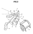
- FIG. 2 is a perspective view showing an arrangement of a seatbelt guide device according to the first embodiment;
- FIG. 3 is a side elevational view of the seatbelt guide device according to the first embodiment;
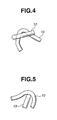
- FIG. 4 is a view in a direction of the arrow line A in FIG. 3.
- FIG. 5 is the view in the direction of the arrow line B in FIG. 3.
- FIG. 6 is a perspective view showing the arrangement of the seatbelt guide device according to a second embodiment of the present invention;
- FIG. 7 is the perspective view showing the arrangement of the seatbelt guide device according to a third embodiment of the present invention;
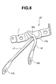
- FIG. 8 is the perspective view showing the arrangement of the seatbelt guide device according to a fourth embodiment of the present invention; and
- FIG. 9 is the view explaining a folded back state of a conventional seatbelt.
-
- In FIG. 1, reference numeral 1 denotes a rear quarter trim disposed behind a rear seat of an automobile (not shown), and a known
retractor 3 is disposed in the rear quarter trim 1 to wind a base end of a seatbelt 2 (shoulder belt) and to accommodate theseatbelt 2 into the rear quarter trim 1. Theseatbelt 2 drawn out of theretractor 3 is guided through aseatbelt guide device 4 disposed in the rear quarter trim 1, extended from abelt extract unit 6 which is disposed on the rear quarter trim 1 at the lower end of arear quarter glass 5, and coupled with a waist belt through a tongue (not shown). - In this embodiment, the
seatbelt guide device 4 has a structure by combining a small bracket fixedly secured to a vehicle body and a rod, and has a required strength while reducing its weight. Theseatbelt guide device 4 has a function for folding back theseatbelt 2 drawn out of theretractor 3 as well as reducing a load applied to the vehicle body by dispersing the load transmitted from theseatbelt 2. - More specifically, as shown in FIGS. 2 and 3, the
seatbelt guide device 4 comprises mainlybrackets rods brackets rods respective rods brackets rod 12 as described below) to secure a required strength. - The important structure is that the
rod 10 corresponds to a first rod of the present invention, therod 11 corresponds to a third rod of the present invention, and therod 13 corresponds to a second rod of the present invention. Further, in FIG. 3 showing a side elevational view, abracket 7 side shows the upper direction of the vehicle body, and abracket 9 side shows the front side thereof. - The
bracket 7 is a slender bracket having holes, which are formed at both ends thereof and through which thebracket 7 is attached to the vehicle body, and a rib-shaped bent portion formed at approximately the center thereof. An end portion of therod 10 is fixedly secured to the bent portion, and the end portion of therod 11 is fixedly secured to thebracket 7 in the vicinity of therod 10. - The
rod 10 is a main rod constituting the main portion of theseatbelt guide device 4 and has an arc-shapedwebbing guide portion 10a formed thereto. Thewebbing guide portion 10a is formed by bending the metal rod member and folds back and guides theseatbelt 2. The end portion of thewebbing guide portion 10a is fixedly secured to thebracket 7, and the base end of the rod-shaped straight portion thereof is secured to thebracket 8. Likewise, therod 11 is also formed by bending the straight metal rod member to a shape approximately similar to that of thewebbing guide portion 10a. The end portion of therod 11 is fixedly secured to thebracket 7, and the base end of the rod-shaped straight portion thereof is fixedly secured to thebracket 8 together with therod 10. - The
bracket 7 is disposed to a portion (first portion) of the vehicle body facing theretractor 3 so that thewebbing guide portion 10a of therod 10 fixedly secured to thebracket 7 faces a desired belt folding back direction, and the straight portions of therods seatbelt 2. The base ends of both therod bracket 8 which is attached to a portion (second portion) of the vehicle body between thebracket 7 and theretractor 3. That is, therod 11 is an auxiliary member for dispersing the load applied to therod 10 and suppressing the deformation of thebracket 7. - The
bracket 8 has two rib-shaped projections disposed approximately in parallel with each other on both the sides of an attachment hole defined approximately at the center of thebracket 8, through which it is attached to the vehicle body, and the base ends of therods reinforcement member 14 formed of a thin sheet metal is wound around and fixedly secured to the straight portions of therods bracket 8 so that therods reinforcement member 14 acting as a support member for coupling therod 10 with therod 11. - In contrast, the approximately L-
shaped rod 12 is used to prevent theseatbelt 2 from being removed from thewebbing guide portion 10a to theretractor 3 side. Therod 12 is disposed approximately in parallel with thebracket 7 with end portion thereof in a lateral direction fixedly secured to the outer periphery of the bent portion of therod 10 located between the straight portion and thewebbing guide portion 10a thereof (refer to FIG. 4), and the other end of therod 12 is opened. - In this case, since the
rod 12 is provided to prevent a removal of theseatbelt 2 from thewebbing guide portion 10a as described above, it does not necessarily have the rod member, and the removal of theseatbelt 2 may be prevented by covering thewebbing guide portion 10a with a resin cover and the like in place of therod 12. - Further, the end portion of the
rod 13 is abutted against and fixedly secured to the inside of the bent portion of therod 10 located between the straight portion and thewebbing guide portion 10a thereof (refer to FIG. 5), and the base end of therod 13 is fixedly secured to the end of the bracket 9 (the end opposite of an attachment hole to the vehicle body) disposed to a portion (third portion) of the vehicle body in the vicinity of thebracket 8. Therod 13 is an auxiliary member for supporting therod 10 from under thewebbing guide portion 10a so as to prevent therod 10 from falling down in the front direction of the vehicle body when a load is applied thereto. - Note that it is preferable that the portions of the
rods seatbelt 2 comes into contact, are covered with resin covers or coated with a resin material, thereby the winding property of theseatbelt 2 can be improved. - In the
seatbelt guide device 4 arranged as described above, theseatbelt 2 extract from theretractor 3 is extended from under the base portions of therods webbing guide portion 10a of therod 10. Then, theseatbelt 2 is suspended and folded back in a predetermined direction by thewebbing guide portion 10a, and extended from thebelt extraction unit 6 of the rear quarter trim 1. Theseatbelt 2 extended from thebelt extraction unit 6 is combined with, for example, a waist seatbelt (not shown) and constitutes a three-point type seatbelt. With this arrangement, the chest of a passenger is securely held by theseatbelt 2 drawn out of thebelt extract unit 6 as well as the waist of the passenger is held by the waist belt (not shown). - At this time, although the seatbelt 2 contacts the
webbing guide portion 10a of therod 10 and a load is applied thereto, theseatbelt 2 fits in the arc shape of thewebbing guide portion 10a and is prevented from slipping down as well as the load is dispersed by the threerods seatbelt 2, since the impact is received by therods rods - Further, the load can be transmitted to the vehicle body under desirable optimum conditions which are set according to the restraining conditions of the respective rods in consideration of the load received from the
seatbelt 2, the radii, the bent shapes, the materials and the span lengths of therespective rods rods - Since the
seatbelt guide device 4 in this embodiment is arranged by using the small andlight brackets rods - Moreover, since a degree of a design freedom of a layout is increased by the reduction in size and weight of the parts, it does not necessarily provide a guide stay and the like in a compartment to fold back the seatbelt by accommodating the
retractor 3 and the seatbeltguide device 4 in the rear quarter trim 1, which contributes to the improvement of the seatbeltguide device 4 as a commercial commodity without spoiling its good appearance in the compartment. - Next, a second embodiment of the present invention will be explained. FIG. 6 is a perspective view showing the arrangement of a seatbelt guide device according to the second embodiment of the present invention.
- The second embodiment simplifies the arrangement of the
seatbelt guide device 4 of the first embodiment described above by omitting therod 11 and thereinforcement member 14 used therein. That is, since therod 11 is used to disperse the load applied to therod 10 and thereinforcement member 14 is used to prevent therods rods seatbelt guide device 4 is not largely affected thereby. Accordingly, a lighter and less expensive seatbelt guide device can be realized by omitting these rods. - As shown in FIG. 6, the
seatbelt guide device 4A of the second embodiment comprises abracket 8A, thebrackets rods rod 11 and thereinforcement member 14. Thebracket 8A is a modification of thebracket 8 and has a smaller size than that of thebracket 8. Thebracket 8A is formed in a shape obtained by removing the rib-shaped projection for securing therod 11 from thebracket 8 of the first embodiment, and the relationship between thebrackets rods seatbelt 2 is dispersed to therods - In the second embodiment, the size of the
bracket 8A can be made smaller than that of thebracket 8 in the first embodiment described above by omitting therod 11 and the reinforcingmember 14. Accordingly, not only the weight and the cost of theseatbelt guide device 4 can be more reduced but also the winding property of the seatbelt can be maintained in a good state even if a layout is such that the distance from a belt folding-back portion to theretractor 3 is short and theseatbelt 2 is twisted by reducing the number and the size of parts. - Next, a third embodiment of the present invention will be explained. FIG. 7 is a perspective view showing the arrangement of a
seatbelt guide device 4B according to the third embodiment of the present invention. - In the third embodiment, the number of parts is reduced by integrating the
rod 12 with therod 13. That is, theseatbelt guide device 4B of the third embodiment shown in FIG. 7 is provided with arod 15 in place of therod 13 used in theseatbelt guide device 4, and the end portion of therod 15 is extended so that the end portion thereof also performs the function of therod 12. - More specifically, the
rod 15 is formed in an L-shape similar to that of therod 12 by extending the end portion of therod 13 that is fixedly secured to the inside of the bent portion of therod 10 located between the straight portion and thewebbing guide portion 10a thereof, and the L-shaped portion of therod 15 forms an easy disconnectionpreventive portion 15a for preventing from unexpectedly removing theseatbelt 2 from thewebbing guide portion 10a. - With the above arrangement, the third embodiment can achieve a further cost reduction by more reducing the number of parts while maintaining an excellent operational easiness similar to that of the second embodiment because it is not necessary to separately provide the
rod 12. - It is needless to say that the
rod 15, which also performs the function of therod 12, may be applied to theseatbelt guide device 4 of the first embodiment. - Next, a fourth embodiment of the present invention will be explained. FIG. 8 is the perspective view showing the arrangement of the seatbelt guide device according to the fourth embodiment of the present invention.
- In the fourth embodiment, brackets for securing rods to the vehicle body are eliminated, and FIG. 8 shows an example that the fourth embodiment is applied to the
seatbelt guide device 4B of the third embodiment to eliminate thebrackets - The
seatbelt guide device 4C shown in FIG. 8 eliminates thebracket 8A by using arod 16 of which base end is modified to permit therod 16 to be directly fixed to the vehicle body in place of therod 10 which is fixedly secured to the vehicle body through thebracket 8A. Further, theseatbelt guide device 4C eliminates thebracket 9 by using arod 17 of which base end is modified to permit therod 17 to be directly fixed to the vehicle body in place of therod 15 which is fixedly secured to the vehicle body through thebracket 9. - That is, the
rod 16 includes awebbing guide portion 16a and a vehiclebody attachment portion 16b. Thewebbing guide portion 16a is formed in the same shape as that of thewebbing guide portion 10a of therod 10, and the vehiclebody attachment portion 16b is formed by molding the end portion of therod 16 at the base end thereof to make flat by a press (or forging) machine and the like, and an attachment hole is drilled therethrough. Thewebbing guide portion 16a is fixedly secured to thebracket 7 at the end portion thereof by welding and the like, and the vehiclebody attachment portion 16b on the base end thereof is directly attached and secured to the vehicle body by a bolt and the like. - Further, the
rod 17 includes an easy disconnectionpreventive portion 17a and a vehiclebody attachment portion 17b. Thepreventive portion 17a is formed in the same shape as that of thepreventive portion 15a of therod 15, and the vehiclebody attachment portion 17b is formed by molding the end portion of therod 17 at the base end thereof to a flat shape by the press (or forging) machine and the like, and the attachment hole is drilled therethrough. The base portion of theremoval preventing portion 17a is fixedly secured to the inside of the bent portion of therod 16 continuous to thewebbing guide portion 16a thereof by welding and the like, and the vehiclebody attachment portion 17b at the base end of therod 17 is directly attached and secured to the vehicle body by the bolt and the like. - With this arrangement, not only the size and the weight of the
seatbelt guide device 4C can be more reduced by further reducing the number of parts but also the degree of design freedom of the layout can be more increased by reducing a space in which theseatbelt guide device 4C is installed. - It is also possible to eliminate the
bracket 7 by forming the end portion of thewebbing guide portion 16a of therod 16 in the same shape as that of the vehiclebody attachment portion 16b on the base end thereof. In this case, the seatbelt guide device can comprise only two rods without using any bracket. - As described above, in these embodiment, since the main rod, in which the guide portion is formed to suspend and fold back the seatbelt, and the auxiliary rod for dispersing the load applied to the main rod are restrained each other and secured to the vehicle body, the seatbelt guide device can be reduced in size and weight while securing the required strength, and the cost of the device can be reduced as well as the degree of design freedom of the layout of it can be improved.
- In the present invention, different embodiments can be arranged in a wide range based on the invention without departing from the spirit and the scope of the present invention.
Claims (9)
- A seatbelt guide device for an automobile for guiding a seatbelt extracted from a retractor, characterized by comprising:wherein the main rod and the auxiliary rod are restrained each other and secured to a vehicle body.a main rod with a guide portion for suspending and folding back the seatbelt (2); andan auxiliary rod for dispersing a load applied to the main rod;
- A seatbelt guide device according to claim 1; characterized in that said load is transmitted to the vehicle body under optimum conditions setted in accordance with the restraining conditions of the main rod and the auxiliary rod.
- A seatbelt guide device according to claim 1 or 2, characterized by further comprising, other rod for preventing from easily disconnecting the seatbelt (2) from the guide portion.
- A device according to any of claims 1 to 3, characterized by further comprising,
a cover for preventing from easily disconnecting the seatbelt (2) from the guide portion. - A device according to any of claims 1 to 4, characterized in that:the main rod has a first rod (10) with the guide portion formed in an arc shape of a part of a rod-shaped member;the auxiliary rod has a second rod (13) with one end secured to the inside of the guide portion and a third rod (11) disposed in parallel with the first rod (10) and coupled with the first rod (10) by a support member (14);one end of the first rod (10) on the guide portion side thereof and one end of the third rod (11) secured to a first portion of the vehicle body confronting the retractor (3) in the same way as the other end of the first rod (10) and the other end of the third rod (11) secured to a second portion of the vehicle body between the first portion and the retractor (3); andthe other end of the second rod (13) secured to a third portion of the vehicle body in the vicinity of the second portion.
- A device according to any of claims 1 to 4, , characterized in that:the main rod has a first rod (10) with the guide portion formed in an arc shape of a part of a rod-shaped member;the auxiliary rod has a second rod (13) with one end is secured to the inside of the guide portion;one end of the first rod (10) on the guide portion side thereof secured to a first portion of the vehicle body confronting the retractor (3) in the same as the other end of the first rod (10) secured to a second portion of the vehicle body between the first portion and the retractor (3); andthe other end of the second rod (13) secured to a third portion of the vehicle body in the vicinity of the second portion.
- A device according to any of claims 1 to 4, characterized in that:the main rod has a first rod (10) with the guide portion formed in an arc shape of a part of a rod-shaped member;the auxiliary rod has a second rod (15) which is fixedly secured to the inside of the guide portion and has a removal preventing portion (15a) formed of the open end thereof extending to a side of the guide portion for preventing the removal of the seatbelt (2) from the guide portion;one end of the first rod (10) on the guide portion side thereof secured to a first portion of the vehicle body confronting the retractor (3) in the same as the other end of the first rod (10) secured to a second portion of the vehicle body between the first portion and the retractor (3); andthe other end of the second rod (13) secured to a third portion of the vehicle body in the vicinity of the second portion.
- A device according to any of claims 1 to 7, further characterized by comprising:a bracket (7, 8, 9) for securing at least one of the main rod and the auxiliary rod to the vehicle body.
- A device according to any of claims 1 to 8, characterized in that at least one of the main rod and the auxiliary rod has a flat-plate-shaped vehicle body attaching portion (16b, 17b) for fixing the rod to the vehicle body.
Applications Claiming Priority (2)
| Application Number | Priority Date | Filing Date | Title |
|---|---|---|---|
| JP2002370725A JP4252796B2 (en) | 2002-12-20 | 2002-12-20 | Automotive seat belt guide device |
| JP2002370725 | 2002-12-20 |
Publications (2)
| Publication Number | Publication Date |
|---|---|
| EP1431138A1 true EP1431138A1 (en) | 2004-06-23 |
| EP1431138B1 EP1431138B1 (en) | 2005-10-19 |
Family
ID=32376346
Family Applications (1)
| Application Number | Title | Priority Date | Filing Date |
|---|---|---|---|
| EP03029008A Expired - Lifetime EP1431138B1 (en) | 2002-12-20 | 2003-12-16 | Guide device for automobile seatbelt |
Country Status (4)
| Country | Link |
|---|---|
| US (1) | US7131669B2 (en) |
| EP (1) | EP1431138B1 (en) |
| JP (1) | JP4252796B2 (en) |
| DE (1) | DE60301939T2 (en) |
Families Citing this family (12)
| Publication number | Priority date | Publication date | Assignee | Title |
|---|---|---|---|---|
| US8408599B2 (en) * | 2009-09-16 | 2013-04-02 | GM Global Technology Operations LLC | Guide loops for a seat belt system |
| US8585090B2 (en) * | 2010-06-29 | 2013-11-19 | Autoliv Asp, Inc. | High efficiency pretensioner |
| US8528987B2 (en) | 2012-01-30 | 2013-09-10 | Autoliv Asp, Inc. | Linear seat belt pretensioner |
| JP5786767B2 (en) * | 2012-03-09 | 2015-09-30 | トヨタ自動車株式会社 | Seat belt retractor mounting structure |
| DE102012010338A1 (en) * | 2012-05-25 | 2013-11-28 | Gm Global Technology Operations, Llc | Seat belt arrangement in motor vehicle, has seat belt associated with backrest of vehicle seat, while belt retractor is provided for shoulder belt portion of seat belt, where belt retractor is arranged below upper end of backrest |
| KR20140131824A (en) * | 2013-05-06 | 2014-11-14 | 아우토리브 디벨롭먼트 아베 | belt bag d-ring assembly f0r vehicles |
| DE102014104435B4 (en) * | 2013-11-19 | 2022-07-28 | Dr. Ing. H.C. F. Porsche Aktiengesellschaft | Belt deflection console and body structure |
| JP6001602B2 (en) * | 2014-07-02 | 2016-10-05 | 本田技研工業株式会社 | Vehicle webbing guide structure |
| JP6198064B2 (en) | 2014-07-04 | 2017-09-20 | トヨタ紡織株式会社 | Assembly structure for vehicle interior materials |
| US10894525B2 (en) * | 2018-11-08 | 2021-01-19 | Polaris Industries Inc. | Seat belt energy management loop |
| US11014528B2 (en) * | 2019-04-19 | 2021-05-25 | Toyota Motor Engineering & Manufacturing North America, Inc. | Energy absorption for D-ring attachment bracket |
| US12194954B2 (en) | 2023-03-17 | 2025-01-14 | Polaris Industries Inc. | Integrated seat belt energy management loop |
Citations (4)
| Publication number | Priority date | Publication date | Assignee | Title |
|---|---|---|---|---|
| DE2545890A1 (en) * | 1975-10-14 | 1977-04-21 | Bayerische Motoren Werke Ag | Reel type safety belt restraint device - has run through fitting displaced from coil reel and belt plane deflector surface |
| JPH1071929A (en) * | 1996-09-02 | 1998-03-17 | Araco Corp | Guiding structure for seat belt |
| JPH10236277A (en) * | 1997-03-01 | 1998-09-08 | Ikuo Kawamata | Seat belt drawing out device |
| DE19901784A1 (en) * | 1998-02-11 | 1999-08-12 | Breed Automotive Tech | Three-point safety belt system for central rear seat in motor vehicle |
Family Cites Families (38)
| Publication number | Priority date | Publication date | Assignee | Title |
|---|---|---|---|---|
| SE387852B (en) * | 1975-01-10 | 1976-09-20 | O L Lindblad | DETECTION DEVICE FOR VEHICLE SAFETY BELTS FITTED WITH TAPE COLLECTION DEVICE |
| US4056271A (en) * | 1975-09-15 | 1977-11-01 | Nissan Motor Company, Limited | Vehicle occupant restraining belt with device to provide an arrangement in which shoulder belt is prevented from touching seated occupant's neck |
| DE2915988C2 (en) * | 1979-04-20 | 1983-01-05 | Daimler-Benz Ag, 7000 Stuttgart | Guide device for belt webbing that can be unwound from and wound onto a supply roll of a seat belt system |
| JPS6027714Y2 (en) * | 1979-11-10 | 1985-08-21 | 日産自動車株式会社 | seat belt retractor |
| JPS6030848U (en) * | 1983-08-08 | 1985-03-02 | 株式会社東海理化電機製作所 | Webbing intermediate support device |
| JPS6121653U (en) * | 1984-07-13 | 1986-02-07 | 株式会社東海理化電機製作所 | webbing guide device |
| JPH0414289Y2 (en) * | 1986-07-22 | 1992-03-31 | ||
| US4786078A (en) * | 1987-06-22 | 1988-11-22 | Schreier Steven E | Shoulder belt adjuster |
| US5149135A (en) * | 1988-06-15 | 1992-09-22 | Mazda Motor Corporation | Front seat shoulder belt and seat back supporting structure |
| JPH02121364U (en) * | 1989-03-13 | 1990-10-02 | ||
| JPH02120273U (en) * | 1989-03-16 | 1990-09-27 | ||
| FR2660263B1 (en) * | 1990-03-30 | 1992-07-24 | Ecia Equip Composants Ind Auto | SELF-LOCKING STRAP RETURN FOR SEAT BELT. |
| US5139282A (en) * | 1991-05-06 | 1992-08-18 | General Motors Corporation | Shoulder belt comfort spring |
| US5176402A (en) * | 1991-08-21 | 1993-01-05 | Indiana Mills & Manufacturing, Inc. | Detachable vehicle belt guide |
| US5340198A (en) * | 1991-09-05 | 1994-08-23 | Murphy Joseph F | Seat belt adjustment device |
| DE4218792A1 (en) * | 1992-06-06 | 1993-12-09 | Bayerische Motoren Werke Ag | Three-point seat belt system for motor vehicles |
| JP3113081B2 (en) * | 1992-08-18 | 2000-11-27 | タカタ株式会社 | Inflatable seat belt device |
| JP3032407B2 (en) | 1993-06-25 | 2000-04-17 | 株式会社クボタ | Self-driving vehicles |
| DE4324785A1 (en) * | 1993-07-23 | 1995-01-26 | Bayerische Motoren Werke Ag | Fastening device for a deflection fitting |
| US5398997A (en) * | 1993-09-07 | 1995-03-21 | Trw Vehicle Safety Systems Inc. | Seat belt system with buckle-responsive retractor lock |
| US5385370A (en) * | 1993-12-27 | 1995-01-31 | Ford Motor Company | Occupant restraint system with improved mounting mechanism |
| US5439253A (en) * | 1994-04-12 | 1995-08-08 | Cari-All Inc. | Automatic retractable safety belt device for a seat compartment of a shopping cart |
| US5411292A (en) * | 1994-04-15 | 1995-05-02 | Allied-Signal Inc. | Seat belt system with locking guide loop assembly |
| US5516148A (en) * | 1994-06-28 | 1996-05-14 | Takata Corporation | Slip anchor for seat belt device |
| US5590907A (en) * | 1995-10-10 | 1997-01-07 | Vehicle Safety Systems, Inc. | Seat belt positioning device and system |
| JPH11198755A (en) | 1998-01-14 | 1999-07-27 | Kasai Kogyo Co Ltd | Seat belt guide device for car |
| US6168206B1 (en) * | 1998-03-02 | 2001-01-02 | Trw Vehicle Safety Systems Inc. | Assembly for protecting a vehicle occupant's head from an impact |
| JP3809736B2 (en) * | 1998-12-24 | 2006-08-16 | タカタ株式会社 | Air belt device |
| US6217069B1 (en) * | 1999-04-12 | 2001-04-17 | Palvannanathan Ganesan | Safety restraint for a horizontal passenger |
| JP4142201B2 (en) * | 1999-04-28 | 2008-09-03 | 株式会社東海理化電機製作所 | Through anchor |
| US6139059A (en) * | 1999-07-01 | 2000-10-31 | Metzger; Ray | Lap belt device |
| JP3785885B2 (en) * | 2000-02-04 | 2006-06-14 | 日産自動車株式会社 | Child seat mounting and child seat mounting structure |
| JP4488598B2 (en) * | 2000-06-21 | 2010-06-23 | 株式会社ニフコ | Seat belt guide |
| US6520588B1 (en) * | 2000-11-16 | 2003-02-18 | Trw Vehicle Safety Systems Inc. | Seat belt guide |
| US6450534B1 (en) * | 2001-05-25 | 2002-09-17 | Cts Corporation | Seat belt tension sensor |
| JP2003011777A (en) * | 2001-06-28 | 2003-01-15 | Tokai Rika Co Ltd | Through anchor |
| DE10153062C1 (en) * | 2001-10-30 | 2003-04-24 | Norbert Janz | Automotive seat belt shoulder harness attachment has belt sliding surface separated from bolt attachment centre point by defined gap |
| US6929286B2 (en) * | 2002-08-26 | 2005-08-16 | Autoliv Asp, Inc. | Energy absorbing turning loop cover |
-
2002
- 2002-12-20 JP JP2002370725A patent/JP4252796B2/en not_active Expired - Fee Related
-
2003
- 2003-12-12 US US10/734,575 patent/US7131669B2/en not_active Expired - Fee Related
- 2003-12-16 DE DE60301939T patent/DE60301939T2/en not_active Expired - Fee Related
- 2003-12-16 EP EP03029008A patent/EP1431138B1/en not_active Expired - Lifetime
Patent Citations (4)
| Publication number | Priority date | Publication date | Assignee | Title |
|---|---|---|---|---|
| DE2545890A1 (en) * | 1975-10-14 | 1977-04-21 | Bayerische Motoren Werke Ag | Reel type safety belt restraint device - has run through fitting displaced from coil reel and belt plane deflector surface |
| JPH1071929A (en) * | 1996-09-02 | 1998-03-17 | Araco Corp | Guiding structure for seat belt |
| JPH10236277A (en) * | 1997-03-01 | 1998-09-08 | Ikuo Kawamata | Seat belt drawing out device |
| DE19901784A1 (en) * | 1998-02-11 | 1999-08-12 | Breed Automotive Tech | Three-point safety belt system for central rear seat in motor vehicle |
Non-Patent Citations (2)
| Title |
|---|
| PATENT ABSTRACTS OF JAPAN vol. 1998, no. 08 30 June 1998 (1998-06-30) * |
| PATENT ABSTRACTS OF JAPAN vol. 1998, no. 14 31 December 1998 (1998-12-31) * |
Also Published As
| Publication number | Publication date |
|---|---|
| DE60301939D1 (en) | 2006-03-02 |
| US7131669B2 (en) | 2006-11-07 |
| DE60301939T2 (en) | 2006-07-27 |
| JP2004196263A (en) | 2004-07-15 |
| JP4252796B2 (en) | 2009-04-08 |
| US20040124690A1 (en) | 2004-07-01 |
| EP1431138B1 (en) | 2005-10-19 |
Similar Documents
| Publication | Publication Date | Title |
|---|---|---|
| US5364170A (en) | Seat belt webbing guide | |
| EP1431138B1 (en) | Guide device for automobile seatbelt | |
| JP2001138864A (en) | Seat belt device of automobile | |
| US6086100A (en) | Method and apparatus for transferring rear shoulder belt loads to a vehicle frame | |
| CN110341806B (en) | Vehicle body rear structure | |
| US6302442B1 (en) | Attachment structure of a seat belt system | |
| US5590907A (en) | Seat belt positioning device and system | |
| US8220829B2 (en) | Roof air bag mounting structure | |
| CN108973927A (en) | Seat safety belt apparatus | |
| WO2018139437A1 (en) | Seatbelt device for vehicle | |
| JP4314991B2 (en) | Car body rear structure | |
| KR100337830B1 (en) | Baggage intrusion prevention structure of trunk room | |
| JP2003226225A (en) | Vehicle retractor mounting structure | |
| JP2000095061A (en) | Vehicle seat belt device | |
| JPH0558240A (en) | Open top type automobile | |
| EP1468881A1 (en) | A seat belt device | |
| JP2001191898A (en) | Vehicle seat belt | |
| JP3911818B2 (en) | Vehicle seat belt device | |
| KR100435387B1 (en) | Structure for preventing bending of slide track for vehicle | |
| US12269417B1 (en) | Rear seat belt anchorage structure for vehicle | |
| JPH0534270Y2 (en) | ||
| CN210822151U (en) | A seat belt device for MPV | |
| JP4449210B2 (en) | Seat belt mounting structure for rear row center seat | |
| JPH0528135Y2 (en) | ||
| KR100206434B1 (en) | Seat belt buckle of a car |
Legal Events
| Date | Code | Title | Description |
|---|---|---|---|
| PUAI | Public reference made under article 153(3) epc to a published international application that has entered the european phase |
Free format text: ORIGINAL CODE: 0009012 |
|
| AK | Designated contracting states |
Kind code of ref document: A1 Designated state(s): AT BE BG CH CY CZ DE DK EE ES FI FR GB GR HU IE IT LI LU MC NL PT RO SE SI SK TR |
|
| AX | Request for extension of the european patent |
Extension state: AL LT LV MK |
|
| GRAP | Despatch of communication of intention to grant a patent |
Free format text: ORIGINAL CODE: EPIDOSNIGR1 |
|
| 17P | Request for examination filed |
Effective date: 20040714 |
|
| GRAS | Grant fee paid |
Free format text: ORIGINAL CODE: EPIDOSNIGR3 |
|
| AKX | Designation fees paid |
Designated state(s): DE FR GB |
|
| GRAA | (expected) grant |
Free format text: ORIGINAL CODE: 0009210 |
|
| RBV | Designated contracting states (corrected) |
Designated state(s): DE FR GB |
|
| AK | Designated contracting states |
Kind code of ref document: B1 Designated state(s): DE FR GB |
|
| REG | Reference to a national code |
Ref country code: GB Ref legal event code: FG4D |
|
| REF | Corresponds to: |
Ref document number: 60301939 Country of ref document: DE Date of ref document: 20060302 Kind code of ref document: P |
|
| ET | Fr: translation filed | ||
| PLBE | No opposition filed within time limit |
Free format text: ORIGINAL CODE: 0009261 |
|
| STAA | Information on the status of an ep patent application or granted ep patent |
Free format text: STATUS: NO OPPOSITION FILED WITHIN TIME LIMIT |
|
| 26N | No opposition filed |
Effective date: 20060720 |
|
| PGFP | Annual fee paid to national office [announced via postgrant information from national office to epo] |
Ref country code: FR Payment date: 20081212 Year of fee payment: 6 |
|
| PGFP | Annual fee paid to national office [announced via postgrant information from national office to epo] |
Ref country code: DE Payment date: 20081211 Year of fee payment: 6 |
|
| PGFP | Annual fee paid to national office [announced via postgrant information from national office to epo] |
Ref country code: GB Payment date: 20081210 Year of fee payment: 6 |
|
| GBPC | Gb: european patent ceased through non-payment of renewal fee |
Effective date: 20091216 |
|
| REG | Reference to a national code |
Ref country code: FR Ref legal event code: ST Effective date: 20100831 |
|
| PG25 | Lapsed in a contracting state [announced via postgrant information from national office to epo] |
Ref country code: FR Free format text: LAPSE BECAUSE OF NON-PAYMENT OF DUE FEES Effective date: 20091231 |
|
| PG25 | Lapsed in a contracting state [announced via postgrant information from national office to epo] |
Ref country code: DE Free format text: LAPSE BECAUSE OF NON-PAYMENT OF DUE FEES Effective date: 20100701 |
|
| PG25 | Lapsed in a contracting state [announced via postgrant information from national office to epo] |
Ref country code: GB Free format text: LAPSE BECAUSE OF NON-PAYMENT OF DUE FEES Effective date: 20091216 |