EP1431056A2 - Optical recording medium - Google Patents
Optical recording medium Download PDFInfo
- Publication number
- EP1431056A2 EP1431056A2 EP03256269A EP03256269A EP1431056A2 EP 1431056 A2 EP1431056 A2 EP 1431056A2 EP 03256269 A EP03256269 A EP 03256269A EP 03256269 A EP03256269 A EP 03256269A EP 1431056 A2 EP1431056 A2 EP 1431056A2
- Authority
- EP
- European Patent Office
- Prior art keywords
- water
- area
- ink receiving
- substantially rectangular
- substrate
- Prior art date
- Legal status (The legal status is an assumption and is not a legal conclusion. Google has not performed a legal analysis and makes no representation as to the accuracy of the status listed.)
- Withdrawn
Links
Images

Classifications
-
- G—PHYSICS
- G11—INFORMATION STORAGE
- G11B—INFORMATION STORAGE BASED ON RELATIVE MOVEMENT BETWEEN RECORD CARRIER AND TRANSDUCER
- G11B23/00—Record carriers not specific to the method of recording or reproducing; Accessories, e.g. containers, specially adapted for co-operation with the recording or reproducing apparatus ; Intermediate mediums; Apparatus or processes specially adapted for their manufacture
- G11B23/38—Visual features other than those contained in record tracks or represented by sprocket holes the visual signals being auxiliary signals
- G11B23/40—Identifying or analogous means applied to or incorporated in the record carrier and not intended for visual display simultaneously with the playing-back of the record carrier, e.g. label, leader, photograph
-
- G—PHYSICS
- G11—INFORMATION STORAGE
- G11B—INFORMATION STORAGE BASED ON RELATIVE MOVEMENT BETWEEN RECORD CARRIER AND TRANSDUCER
- G11B7/00—Recording or reproducing by optical means, e.g. recording using a thermal beam of optical radiation by modifying optical properties or the physical structure, reproducing using an optical beam at lower power by sensing optical properties; Record carriers therefor
- G11B7/24—Record carriers characterised by shape, structure or physical properties, or by the selection of the material
Definitions
- a size of the substantially rectangular area needs to be varied depending on a thermal transfer area (thermal head contact area) in thermal transfer recording. Particularly, when printing is performed with the thermal head contacting the label side such as for printing a solid image, heat from the thermal head affects a range larger than the thermal transfer area. Therefore, the substantially rectangular area is formed so as to include overlapping area of the thermal head.
- the substantially rectangular smooth area is preferably formed of at least water-insoluble ink (for example, trade name: UVSP THERMAL INK, manufactured by Teikoku Printing Inks Mfg. Co., Ltd. ) or a known water-insoluble material.
- water-insoluble ink for example, trade name: UVSP THERMAL INK, manufactured by Teikoku Printing Inks Mfg. Co., Ltd.
- a known water-insoluble material for example, trade name: UVSP THERMAL INK, manufactured by Teikoku Printing Inks Mfg. Co., Ltd.
- the height of the protrusion By limiting the height of the protrusion not to exceed 5 ⁇ m, the print defects such as described above can be effectively prevented. More preferable height of the protrusion is not more than 3 ⁇ m.
- a depression is present in the substantially rectangular areas 10a' and 10b', an image obtained thereon by printing, or the like, may have a defect such as a blank spot. From a standpoint of preventing such defects, it is preferable to have a surface roughness (arithmetic average roughness : Ra) be not more than 0.1 ⁇ m, while the height of the protrusion is limited to not more than 5 ⁇ m.
- the substantially rectangular area partially overlaps with a text information portion (corresponding to characters "A B C" in Fig. 1) or with the water-based ink receiving area 11 and a difference in level is created therein, the text information portion and the water-based ink receiving area 11 respectively form a protrusion.
- the height of the protrusion is greater than above-described 5 ⁇ m, print defects are caused.
- the substantially rectangular area so as not to overlap with a text information portion such as described above or the water-based ink receiving area 11. If the substantially rectangular area overlaps with a text information portion or the water-based ink receiving area 11, then the height of the protrusion is limited to not more than 5 ⁇ m. Further, if the water-based ink receiving area overlaps with the water-insoluble ink receiving area, the water-insoluble ink receiving area is formed to have an area larger than the contact area of the thermal head of the printer, so that the water-insoluble ink receiving area overlaps with the water-based ink receiving area at the outside of the contact area.
- the water-based ink receiving area 11 can be formed on a surface of the protective layer or the protective substrate using an ink-jet receiving ink (for example, trade name: UVSPJR INK manufactured by Teikoku Printing Inks Mfg. Co., Ltd.) or a material described in Japanese Patent Application Laid-Open (JP-A) No. 2001-325750 (particularly, a material used in Examples), or the like.
- an ink-jet receiving ink for example, trade name: UVSPJR INK manufactured by Teikoku Printing Inks Mfg. Co., Ltd.
- JP-A Japanese Patent Application Laid-Open
- Fig. 1 the arrangement shown in Fig. 1 is only an example and is not intended to limit the invention.
- the water-insoluble ink receiving areas and the water-based ink receiving area are adjacent to each other in Fig. 1, these areas may be spaced apart from each other. These areas may be formed in various layouts in consideration of design, or the like. For example, there may be water-based ink receiving areas at upper and lower portions (as shown in the drawing) of the label side and a water-insoluble ink receiving area provided therebetween.
- optical recording medium of the invention having the label side such as described above can be applied to an optical recording medium having a recording layer on/from which information can be recorded/reproduced using laser light, or an optical recording medium having a recording section (pits) including recorded information which can be reproduced using laser light.
- any of various materials used as a substrate in conventional optical recording media can be selected.
- glass examples thereof include glass; acrylic resins such as polycarbonate and polymethylmethacrylate; vinyl chloride resins such as polyvinyl chloride and vinyl chloride copolymer; epoxy resin; amorphous polyolefine; polyester; metals such as aluminum; and the like. These materials may be used in combination, as desired.
- a track pitch of the pre-groove preferably ranges from 300 to 900 nm, more preferably from 350 to 850 nm, and even more preferably from 400 to 800 nm. If the track pitch is less than 300 nm, it becomes difficult to precisely form the pre-groove and problems such as cross talk may occur. If the track pitch exceeds 900 nm, recording density may be reduced.
- a half-width of the pre-groove preferably ranges from 200 to 400 nm, more preferably from 230 to 380 nm, and even more preferably from 250 to 350 nm. If the half-width is less than 200 nm, the groove may not sufficiently be transferred at the time of pressing, and error rate of record may be increased. If the half-width exceeds 400 nm, pits formed during recording may be widened and this may cause cross talk, or a sufficient degree of modulation may not be obtained.
- a track pitch of the pre-groove preferably ranges from 1.2 to 2.0 ⁇ m, more preferably from 1.4 to 1.8 ⁇ m, and even more preferably from 1.55 to 1.65 ⁇ m .
- a half-width of the pre-groove preferably ranges from 400 to 650 nm, more preferably from 480 to 600 nm, and even more preferably from 500 to 580 nm.
- the recording layer is formed by: dissolving a dye, which is a recording substance, in a suitable solvent together with a binder, and the like, to prepare a coating solution; coating the coating solution using spin coating on a side of the substrate on which a pre-groove is formed to form a coating film; and drying the coating film.
- dyes described, for example, in JP-A Nos. 4-74690, 8-127174, 11-53758, 11-334204, 11-334205, 11-334206, 11-334207, 2000-43423, 2000-108513 and 2000-158818 are also preferably used.
- Examples of the solvent for the coating solution include esters such as butyl acetate, ethyl lactate and 2-methoxyethyl acetate; ketones such as methyl ethyl ketone, cyclohexanone and methyl isobutyl ketone; chlorinated hydrocarbons such as dichloromethane, 1,2-dichloromethane and chloroform; amides such as dimethylformamide; hydrocarbons such as methylcyclohexane; ethers such as tetrahydrofuran, ethylether and dioxane; alcohols such as ethanol, n-propanol, isopropanol and n-butanol diacetone alcohol; fluorine solvents such as 2,2,3,3-tetrafluoropropanol; glycol ethers such as ethylene glycol monomethyl ether, ethylene glycol monoethyl ether and propylene glycol monomethyl ether; and the like.
- the solvents can be used alone or in combination of two or more of them considering solubility of the recording substance to be used. Further, various additives such as an antioxidant, a UV absorbent, a plasticizer and a lubricant may be added in the coating solution, as required.
- a binder examples thereof include natural organic polymers such as gelatin, cellulose derivatives, dextran, rosin and rubber; and synthetic organic polymers, for example, hydrocarbon resins such as polyethylene, polypropylene, polystyrene and polyisobutylene; vinyl resins such as polyvinyl chloride, polyvinylidene chloride and polyvinyl chloride/polyvinyl acetate copolymer; acrylic resins such as poly(methyl acrylate) and poly(methyl methacrylate); polyvinyl alcohol, chlorinated polyethylene, epoxy resins, butyral resins, rubber derivatives, and precondensates of a thermosetting resin such as phenol-formaldehyde resin.
- hydrocarbon resins such as polyethylene, polypropylene, polystyrene and polyisobutylene
- vinyl resins such as polyvinyl chloride, polyvinylidene chloride and polyvinyl chloride/polyvinyl acetate copolymer
- the amount of the binder generally ranges from 0.01 time to 50 times (mass ratio), and preferably from 0.1 time to 5 times (mass ratio) of the recording materials.
- the concentration of the recording substance present in thus prepared coating solution generally ranges from 0.01 to 10% by mass, and preferably from 0.1 to 5% by mass.
- spin coating is applied as described above.
- a conventionally known coating apparatus can be used for coating.
- the recording layer may have a single layer structure or a multiple layer structure.
- a thickness of the recording layer generally ranges from 20 to 500 nm, preferably from 30 to 300 nm, and more preferably from 50 to 100 nm.
- the recording layer may contain various anti-fading agents in order to improve light fastness of the recording layer.
- a singlet oxygen quencher is generally employed, and those described in known patent specifications and other publications can be used. Specific examples thereof include those described in JP-A Nos. 58-175693, 59-81194, 60-18387, 60-19586, 60-19587, 60-35054, 60-36190, 60-36191, 60-44554, 60-44555, 60-44389, 60-44390, 60-54892, 60-47069, 63-209995 and 4-25492; Japanese Patent Application Publication (JP-B) Nos. 1-38680 and 6-26028; German Patent No. 350,399; and the Journal of the Chemical Society of Japan, Oct. 1992, page 1141.
- the amount of the anti-fading agent such as a singlet oxygen quencher to be used generally ranges from 0.1 to 50% by mass, preferably from 0.5 to 45% by mass, more preferably from 3 to 40% by mass, and particularly preferably from 5 to 25% by mass of the dye.
- the recording layer is preferably formed of a phase change recording material comprising at least Ag, Al, Te, Sb, which can assume at least two states: crystalline state and amorphous state.
- a phase change recording material comprising at least Ag, Al, Te, Sb, which can assume at least two states: crystalline state and amorphous state.
- Such a recording layer can be formed by a known method.
- a light reflecting material is deposited on the recording layer by vapor deposition, spattering or ion plating to form the light reflecting layer.
- a mask is used to control an area in which the light reflecting layer is formed.
- a light reflecting material having high reflectivity to laser light is used.
- the reflectivity is preferably 70% or more.
- Examples of the light reflecting material with high reflectivity include metals and semimetals such as Mg, Se, Y, Ti, Zr, Hf, V, Nb, Ta, Cr, Mo, W, Mn, Re, Fe, Co, Ni, Ru, Rh, Pd, Ir, Pt, Cu, Ag, Au, Zn, Cd, Al, Ga, In, Si, Ge, Te, Pb, Po, Sn and Bi, as well as stainless steel.
- These light reflecting materials may be used alone or in combination of two or more, or in a form of alloy.
- Cr, Ni, Pt, Cu, Ag, Au, Al and stainless steel are preferable
- Au, Ag, Al and their alloys are particularly preferable
- Au, Ag and their alloys are most preferable.
- a thickness of the light reflecting layer generally ranges from 10 to 300 nm, and preferably from 50 to 200 nm.
- the protective layer is formed on the light reflecting layer.
- the protective layer is formed by spin coating.
- spin coating By applying spin coating, the protective layer can be formed without damaging the recording layer (such as dissolution of the dye, or chemical reaction between the dye and the protective layer).
- a rotation speed for spin coating is preferably from 50 to 8000 rpm, and more preferably from 100 to 5000 rpm from the viewpoint of forming a uniform layer and preventing damage to the recording layer.
- ultraviolet curing resin used in the protective layer
- a ultraviolet irradiation lamp a metal halide lamp
- the coated ultraviolet curing resin may be left for a certain time before it is cured, as necessary.
- the protective layer prevents penetration of moisture and formation of scratch.
- Preferable materials for forming the protective layer include ultraviolet curing resins, visible light curing resins, thermosetting resins, silicon dioxide, and the like. Among them, ultraviolet curing resins are particularly preferable.
- An example of the ultraviolet curing resin is SD-640 manufactured by Dai-Nippon Ink and Chemical Co., Ltd. Further, SD-347 (trade name, manufactured by Dai-Nippon Ink and Chemical Co., Ltd.), SD-694 (trade name, manufactured by Dai-Nippon Ink and Chemical Co., Ltd.), SKCD 1051 (trade name, manufactured by SKC), and the like, can also be used.
- a thickness of the protective layer preferably ranges from 1 to 200 ⁇ m, and more preferably from 50 to 150 ⁇ m.
- the protective layer In a layer structure where the protective layer is used as an optical path for laser, the protective layer is required to have transparency.
- transparency used herein means being transparent enough to transmit writing and reading light beams (transmittance of 90 or more).
- an adhesive layer comprising a ultraviolet curing resin, or the like, and a substrate (having a thickness of about 0.6 mm, made of a material similar to that of the above-described substrate), which serves as the protective substrate, are laminated.
- the ultraviolet curing resin e.g., trade name: SD-640, manufactured by Dai-Nippon Ink and Chemical Co., Ltd.
- the adhesive layer for example, a polycarbonate substrate (having a thickness of 0.6 mm), which serves as the protective substrate, is placed, and ultraviolet light is irradiated from above the substrate to cure the ultraviolet curing resin, thereby effecting adhesion.
- the optical recording medium of the invention can also be applied to an optical recording medium which has a narrower track pitch than that of a conventional DVD, or the like, and on/from which information can be written/read with laser light having a smaller wavelength than that of conventionally used laser light.
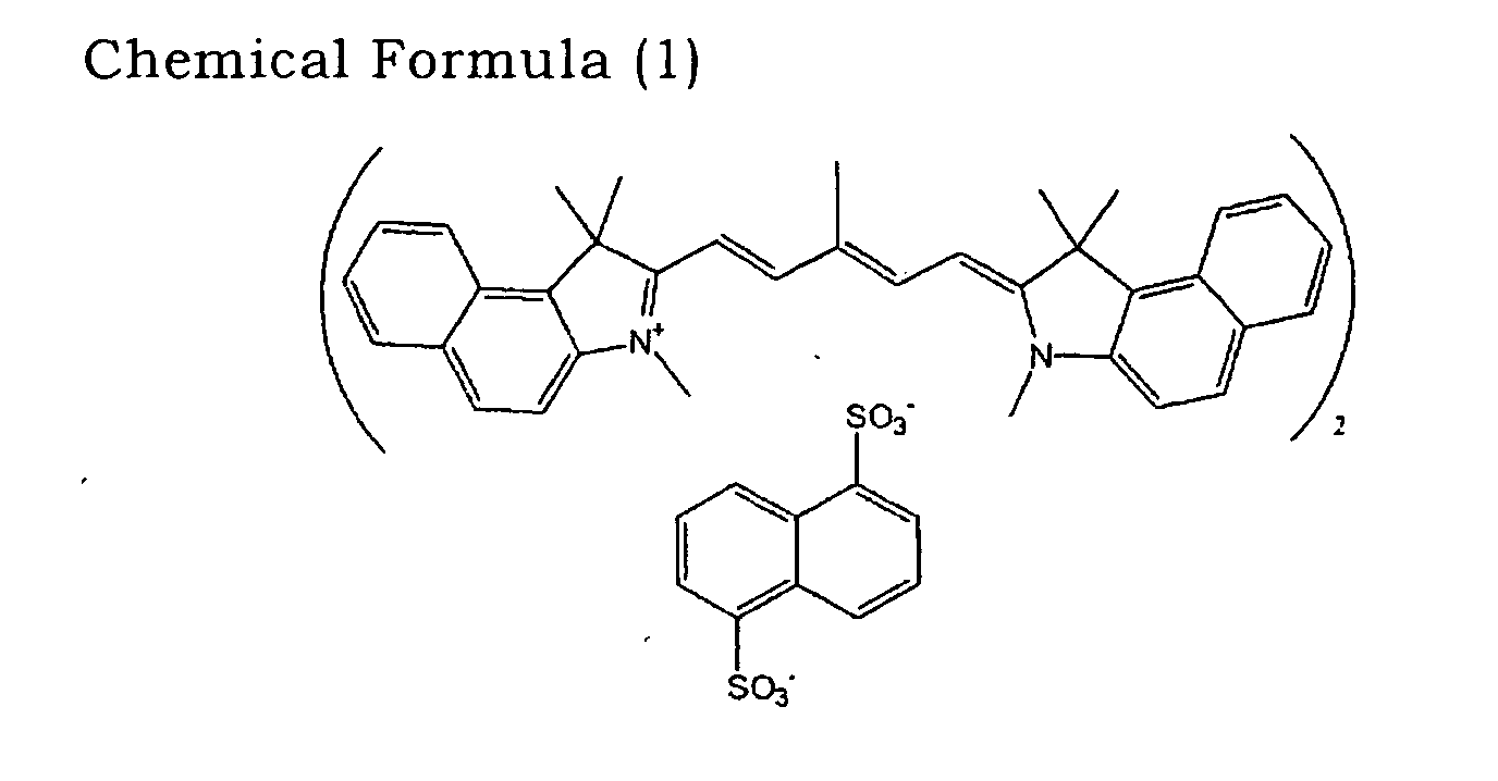
- cyanine dye represented by Chemical Formula (1) below was added, and was dissolved by being exposed to ultrasonic wave for 90 minutes, to prepare a recording layer forming coating solution.
- the recording layer forming coating solution was coated by spin coating on an injection-molded polycarbonate-resin substrate (polycarbonate: manufactured by Teijin, trade name: PANLITE AD5503), which has a thickness of 1.2 mm, an inner diameter of 15 mm and an outer diameter of 120 mm and is provided with a spiral groove, at a side thereof with the groove, to form a recording layer (thickness: 80 nm).
- conditions for spin coating were: coating rotation speed of 500 rpm was kept for 25 seconds, drying rotation speed of 1500 rpm was kept for 30 seconds, and spreading-off rotation speed of 3000 rpm was kept for 10 seconds.
- a light reflecting layer (thickness: 80 nm) made of Ag was formed by DC magnetron sputtering.
- a ultraviolet curing resin (trade name: SD-318, manufactured by Dai-Nippon Ink and Chemical Co., Ltd.) was coated by spin coating, and the coated surface was exposed to ultraviolet light to cure the ultraviolet curing resin, to form a protective layer (thickness: 9 ⁇ m).
- the water-based ink receiving area 11 and the water-insoluble ink receiving areas 10a and 10b were provided as shown in Fig. 1, to produce an optical recording medium.
- the water-insoluble ink receiving areas 10 and 10b were formed by screen printing ultraviolet curing screen ink for receiving (ink from) a thermal transfer ink ribbon (trade name: UVSP THERMAL INK, manufactured by Teikoku Printing Inks Mfg. Co., Ltd.), and exposing the ink surface to ultraviolet light to cure the ink.
- a thermal transfer ink ribbon (trade name: UVSP THERMAL INK, manufactured by Teikoku Printing Inks Mfg. Co., Ltd.), and exposing the ink surface to ultraviolet light to cure the ink.
- the water-based ink receiving area 11 was formed by screen printing ultraviolet curing screen ink for receiving (ink from) an inkjet (trade name: UVSPJR INK, manufactured by Teikoku Printing Inks Mfg. Co., Ltd.), and exposing the ink surface to ultraviolet light.
- an inkjet trade name: UVSPJR INK, manufactured by Teikoku Printing Inks Mfg. Co., Ltd.
- the text portion Since the area X (5 cm 2 ) included the formed text portion, the text portion created a difference in level, and therefore protrusions of 20 ⁇ m high were formed.
- the water-based ink receiving area 11 present in the area Y (10 cm 2 ) created a protrusion of 10 ⁇ m high.
- the water-based ink receiving area 11 present in the area Z (5 cm 2 ) also created a protrusion, however, a height thereof was 5 ⁇ m.
Landscapes
- Optical Record Carriers And Manufacture Thereof (AREA)
Abstract
Description
Claims (8)
- An optical recording medium comprising:wherein at least one of the water-insoluble ink receiving area comprises a substantially rectangular smooth area.a substrate;a recording layer formed on the substrate, on which information can be recorded using laser light;one of a protective layer and a protective substrate provided on the recording layer; anda water-based ink receiving area and a water-insoluble ink receiving area formed on said one of the protective layer and the protective substrate,
- The optical recording medium according to claim 1, wherein the substantially rectangular smooth area has an area of at least 5 cm2.
- The optical recording medium according to claim 1, wherein the substantially rectangular smooth area includes no protrusion having a height exceeding 5 µm.
- The optical recording medium according to claim 1, wherein the substantially rectangular smooth area comprises at least one of a water-insoluble ink and a water-insoluble material.
- An optical recording medium comprising:wherein at least a portion of the water-insoluble ink receiving area, at which a thermal head of a printer overlaps, comprises a substantially rectangular smooth area.a substrate;a recording layer formed on the substrate, on which information can be recorded using laser light;one of a protective layer and a protective substrate provided on the recording layer; anda water-based ink receiving area and a water-insoluble ink receiving area formed on said one of the protective layer and the protective substrate,
- The optical recording medium according to claim 5, wherein the substantially rectangular smooth area has an area of at least 5 cm2.
- The optical recording medium according to claim 5, wherein the substantially rectangular smooth area includes no protrusion having a height exceeding 5 µm.
- The optical recording medium according to claim 5, wherein the substantially rectangular smooth area comprises at least one of a water-insoluble ink and a water-insoluble material.
Applications Claiming Priority (2)
| Application Number | Priority Date | Filing Date | Title |
|---|---|---|---|
| JP2002292776 | 2002-10-04 | ||
| JP2002292776A JP2004127456A (en) | 2002-10-04 | 2002-10-04 | Optical recording medium |
Publications (2)
| Publication Number | Publication Date |
|---|---|
| EP1431056A2 true EP1431056A2 (en) | 2004-06-23 |
| EP1431056A3 EP1431056A3 (en) | 2005-07-06 |
Family
ID=32283933
Family Applications (1)
| Application Number | Title | Priority Date | Filing Date |
|---|---|---|---|
| EP03256269A Withdrawn EP1431056A3 (en) | 2002-10-04 | 2003-10-03 | Optical recording medium |
Country Status (4)
| Country | Link |
|---|---|
| US (1) | US20040133905A1 (en) |
| EP (1) | EP1431056A3 (en) |
| JP (1) | JP2004127456A (en) |
| TW (1) | TW200415608A (en) |
Families Citing this family (6)
| Publication number | Priority date | Publication date | Assignee | Title |
|---|---|---|---|---|
| JP4077781B2 (en) * | 2003-11-18 | 2008-04-23 | 富士フイルム株式会社 | Visible information recording method and recording apparatus for optical information recording medium |
| JP4551701B2 (en) * | 2004-06-14 | 2010-09-29 | 富士フイルム株式会社 | Protective film forming composition for immersion exposure and pattern forming method using the same |
| EP1971982A4 (en) * | 2005-03-03 | 2009-08-19 | Enxnet Inc | Optical disc having a reduced planar thickness |
| US7716695B2 (en) * | 2005-10-07 | 2010-05-11 | Enxnet, Inc. | Thin optical disc having remote reading capability |
| WO2007044567A2 (en) * | 2005-10-07 | 2007-04-19 | Enxnet, Inc. | Thin optical disc having remote reading capability |
| US20080291815A1 (en) * | 2007-05-23 | 2008-11-27 | Imation Corp. | Topographical surface label formed in an optical disk substrate |
Family Cites Families (11)
| Publication number | Priority date | Publication date | Assignee | Title |
|---|---|---|---|---|
| JPH0650876Y2 (en) * | 1987-03-31 | 1994-12-21 | 三洋電機株式会社 | Optical audio disc |
| KR0185765B1 (en) * | 1993-04-10 | 1999-04-15 | 가와다 미쓰구 | Optical information medium and method for fabricating same |
| KR100209819B1 (en) * | 1993-10-18 | 1999-07-15 | 사또 아끼오 | Optical recording medium, a method for printing on the surface of the same, and ultraviolet curable ink |
| JP2541529Y2 (en) * | 1994-06-06 | 1997-07-16 | 三洋電機株式会社 | Optical recording disc |
| JP3364336B2 (en) * | 1994-09-08 | 2003-01-08 | ティーディーケイ株式会社 | Optical disc and recording material |
| EP0863503A3 (en) * | 1997-02-28 | 2001-01-31 | Eastman Kodak Company | Compact disk with human readable information on an internal surface |
| DE69836194T2 (en) * | 1997-12-24 | 2007-02-01 | Fuji Photo Film Co., Ltd., Minami-Ashigara | Medium for optical information storage |
| GB2340292B (en) * | 1998-07-28 | 2002-10-23 | Ricoh Kk | Optical data storage medium capable of reversibly displaying information |
| JP3840345B2 (en) * | 1999-03-19 | 2006-11-01 | 富士写真フイルム株式会社 | Optical information recording medium |
| EP1154418B1 (en) * | 2000-04-27 | 2008-07-16 | Mitsubishi Kagaku Media Co., Ltd. | Optical recording medium |
| EP1497138B1 (en) * | 2002-04-25 | 2007-09-12 | Canon Finetech Inc. | Recording media |
-
2002
- 2002-10-04 JP JP2002292776A patent/JP2004127456A/en active Pending
-
2003
- 2003-10-03 EP EP03256269A patent/EP1431056A3/en not_active Withdrawn
- 2003-10-03 TW TW092127374A patent/TW200415608A/en unknown
- 2003-10-03 US US10/677,491 patent/US20040133905A1/en not_active Abandoned
Also Published As
| Publication number | Publication date |
|---|---|
| US20040133905A1 (en) | 2004-07-08 |
| EP1431056A3 (en) | 2005-07-06 |
| JP2004127456A (en) | 2004-04-22 |
| TW200415608A (en) | 2004-08-16 |
Similar Documents
| Publication | Publication Date | Title |
|---|---|---|
| US20050180308A1 (en) | Optical recording medium and method of recording an image | |
| EP1431056A2 (en) | Optical recording medium | |
| US20030169679A1 (en) | Optical recording medium | |
| US20070237051A1 (en) | Optical Recording Medium and Recording Method | |
| US20050123711A1 (en) | Optical information recording medium and information recording method | |
| CN101019179A (en) | Method of manufacturing optical information recording medium | |
| JP2005149645A (en) | Optical information recording medium, optical information recording medium group, its management method, and its information recording method | |
| US20070269652A1 (en) | Optical Disk | |
| JP2006260728A (en) | Optical disk | |
| US6818386B2 (en) | Method for manufacturing a bonded optical disc | |
| US20080046908A1 (en) | Original glass plate, method of producing original glass plate, stamper for optical recording medium, and method of producing stamper | |
| US20090008257A1 (en) | Method of producing stamper for optical recording medium, method of producing substrate, and method of producing optical recording medium | |
| US20030189891A1 (en) | Optical information recording medium and production process thereof | |
| EP1394788A2 (en) | Optical information recording medium | |
| JP2006155751A (en) | Optical disk | |
| US20080159116A1 (en) | Method for Producing Optical Recording Medium | |
| US20080080361A1 (en) | Optical Recording Medium | |
| JP2006040440A (en) | Image recording method to optical disk | |
| JP2005285167A (en) | Optical recording medium | |
| JP2004280930A (en) | Protective sheet set for optical recording media | |
| JP2006031899A (en) | Optical disk | |
| JP2004280929A (en) | Protective sheet for optical recording media | |
| JP2006228278A (en) | Optical disk | |
| JP2008146726A (en) | Optical information recording medium, substrate, stamper, mold, and method of manufacturing optical information recording medium | |
| JP2008084458A (en) | Optical recording medium |
Legal Events
| Date | Code | Title | Description |
|---|---|---|---|
| PUAI | Public reference made under article 153(3) epc to a published international application that has entered the european phase |
Free format text: ORIGINAL CODE: 0009012 |
|
| AK | Designated contracting states |
Kind code of ref document: A2 Designated state(s): AT BE BG CH CY CZ DE DK EE ES FI FR GB GR HU IE IT LI LU MC NL PT RO SE SI SK TR |
|
| AX | Request for extension of the european patent |
Extension state: AL LT LV MK |
|
| PUAL | Search report despatched |
Free format text: ORIGINAL CODE: 0009013 |
|
| AK | Designated contracting states |
Kind code of ref document: A3 Designated state(s): AT BE BG CH CY CZ DE DK EE ES FI FR GB GR HU IE IT LI LU MC NL PT RO SE SI SK TR |
|
| AX | Request for extension of the european patent |
Extension state: AL LT LV MK |
|
| 17P | Request for examination filed |
Effective date: 20051024 |
|
| STAA | Information on the status of an ep patent application or granted ep patent |
Free format text: STATUS: THE APPLICATION HAS BEEN WITHDRAWN |
|
| AKX | Designation fees paid |
Designated state(s): DE FR GB |
|
| 18W | Application withdrawn |
Effective date: 20060316 |