EP1431048A1 - Method of smoothing surface of printing paper, smoothing apparatus, and printer with the smoothing apparatus - Google Patents
Method of smoothing surface of printing paper, smoothing apparatus, and printer with the smoothing apparatus Download PDFInfo
- Publication number
- EP1431048A1 EP1431048A1 EP03257887A EP03257887A EP1431048A1 EP 1431048 A1 EP1431048 A1 EP 1431048A1 EP 03257887 A EP03257887 A EP 03257887A EP 03257887 A EP03257887 A EP 03257887A EP 1431048 A1 EP1431048 A1 EP 1431048A1
- Authority
- EP
- European Patent Office
- Prior art keywords
- heat generating
- heat
- printing paper
- thermal head
- protection layer
- Prior art date
- Legal status (The legal status is an assumption and is not a legal conclusion. Google has not performed a legal analysis and makes no representation as to the accuracy of the status listed.)
- Granted
Links
- 238000009499 grossing Methods 0.000 title claims abstract description 26
- 238000000034 method Methods 0.000 title claims abstract description 17
- 239000010410 layer Substances 0.000 description 66
- 239000010408 film Substances 0.000 description 10
- 238000010438 heat treatment Methods 0.000 description 8
- 239000000976 ink Substances 0.000 description 8
- 239000002932 luster Substances 0.000 description 6
- 230000017525 heat dissipation Effects 0.000 description 5
- 239000000758 substrate Substances 0.000 description 5
- 239000000463 material Substances 0.000 description 4
- 238000003825 pressing Methods 0.000 description 3
- 239000010409 thin film Substances 0.000 description 3
- VYPSYNLAJGMNEJ-UHFFFAOYSA-N Silicium dioxide Chemical compound O=[Si]=O VYPSYNLAJGMNEJ-UHFFFAOYSA-N 0.000 description 2
- 230000020169 heat generation Effects 0.000 description 2
- 239000000314 lubricant Substances 0.000 description 2
- 229920005989 resin Polymers 0.000 description 2
- 239000011347 resin Substances 0.000 description 2
- 229920002050 silicone resin Polymers 0.000 description 2
- 238000000859 sublimation Methods 0.000 description 2
- 230000008022 sublimation Effects 0.000 description 2
- XOLBLPGZBRYERU-UHFFFAOYSA-N tin dioxide Chemical compound O=[Sn]=O XOLBLPGZBRYERU-UHFFFAOYSA-N 0.000 description 2
- 229910018487 Ni—Cr Inorganic materials 0.000 description 1
- 229910019142 PO4 Inorganic materials 0.000 description 1
- 229920002845 Poly(methacrylic acid) Polymers 0.000 description 1
- 229910052581 Si3N4 Inorganic materials 0.000 description 1
- 229910004479 Ta2N Inorganic materials 0.000 description 1
- 229910004481 Ta2O3 Inorganic materials 0.000 description 1
- 239000000919 ceramic Substances 0.000 description 1
- 229910052804 chromium Inorganic materials 0.000 description 1
- 229910052681 coesite Inorganic materials 0.000 description 1
- 229910052906 cristobalite Inorganic materials 0.000 description 1
- 238000007599 discharging Methods 0.000 description 1
- 239000011521 glass Substances 0.000 description 1
- 239000011810 insulating material Substances 0.000 description 1
- 230000001788 irregular Effects 0.000 description 1
- 239000002184 metal Substances 0.000 description 1
- 229910052751 metal Inorganic materials 0.000 description 1
- 125000002496 methyl group Chemical group [H]C([H])([H])* 0.000 description 1
- 238000012986 modification Methods 0.000 description 1
- 230000004048 modification Effects 0.000 description 1
- 229910003465 moissanite Inorganic materials 0.000 description 1
- 239000010452 phosphate Substances 0.000 description 1
- -1 phosphate ester Chemical class 0.000 description 1
- 239000011241 protective layer Substances 0.000 description 1
- 238000007789 sealing Methods 0.000 description 1
- 229910010271 silicon carbide Inorganic materials 0.000 description 1
- 239000000377 silicon dioxide Substances 0.000 description 1
- 229920002545 silicone oil Polymers 0.000 description 1
- 239000000344 soap Substances 0.000 description 1
- 238000004544 sputter deposition Methods 0.000 description 1
- 229910052682 stishovite Inorganic materials 0.000 description 1
- 229910052905 tridymite Inorganic materials 0.000 description 1
- 229910052721 tungsten Inorganic materials 0.000 description 1
- 238000001771 vacuum deposition Methods 0.000 description 1
Images



Classifications
-
- B—PERFORMING OPERATIONS; TRANSPORTING
- B41—PRINTING; LINING MACHINES; TYPEWRITERS; STAMPS
- B41J—TYPEWRITERS; SELECTIVE PRINTING MECHANISMS, i.e. MECHANISMS PRINTING OTHERWISE THAN FROM A FORME; CORRECTION OF TYPOGRAPHICAL ERRORS
- B41J11/00—Devices or arrangements of selective printing mechanisms, e.g. ink-jet printers or thermal printers, for supporting or handling copy material in sheet or web form
- B41J11/0005—Curl smoothing, i.e. smoothing down corrugated printing material, e.g. by pressing means acting on wrinkled printing material
-
- B—PERFORMING OPERATIONS; TRANSPORTING
- B41—PRINTING; LINING MACHINES; TYPEWRITERS; STAMPS
- B41J—TYPEWRITERS; SELECTIVE PRINTING MECHANISMS, i.e. MECHANISMS PRINTING OTHERWISE THAN FROM A FORME; CORRECTION OF TYPOGRAPHICAL ERRORS
- B41J11/00—Devices or arrangements of selective printing mechanisms, e.g. ink-jet printers or thermal printers, for supporting or handling copy material in sheet or web form
- B41J11/0015—Devices or arrangements of selective printing mechanisms, e.g. ink-jet printers or thermal printers, for supporting or handling copy material in sheet or web form for treating before, during or after printing or for uniform coating or laminating the copy material before or after printing
-
- B—PERFORMING OPERATIONS; TRANSPORTING
- B41—PRINTING; LINING MACHINES; TYPEWRITERS; STAMPS
- B41J—TYPEWRITERS; SELECTIVE PRINTING MECHANISMS, i.e. MECHANISMS PRINTING OTHERWISE THAN FROM A FORME; CORRECTION OF TYPOGRAPHICAL ERRORS
- B41J2/00—Typewriters or selective printing mechanisms characterised by the printing or marking process for which they are designed
- B41J2/315—Typewriters or selective printing mechanisms characterised by the printing or marking process for which they are designed characterised by selective application of heat to a heat sensitive printing or impression-transfer material
- B41J2/32—Typewriters or selective printing mechanisms characterised by the printing or marking process for which they are designed characterised by selective application of heat to a heat sensitive printing or impression-transfer material using thermal heads
- B41J2/325—Typewriters or selective printing mechanisms characterised by the printing or marking process for which they are designed characterised by selective application of heat to a heat sensitive printing or impression-transfer material using thermal heads by selective transfer of ink from ink carrier, e.g. from ink ribbon or sheet
-
- B—PERFORMING OPERATIONS; TRANSPORTING
- B41—PRINTING; LINING MACHINES; TYPEWRITERS; STAMPS
- B41J—TYPEWRITERS; SELECTIVE PRINTING MECHANISMS, i.e. MECHANISMS PRINTING OTHERWISE THAN FROM A FORME; CORRECTION OF TYPOGRAPHICAL ERRORS
- B41J2/00—Typewriters or selective printing mechanisms characterised by the printing or marking process for which they are designed
- B41J2/315—Typewriters or selective printing mechanisms characterised by the printing or marking process for which they are designed characterised by selective application of heat to a heat sensitive printing or impression-transfer material
- B41J2/32—Typewriters or selective printing mechanisms characterised by the printing or marking process for which they are designed characterised by selective application of heat to a heat sensitive printing or impression-transfer material using thermal heads
- B41J2/335—Structure of thermal heads
- B41J2/33505—Constructional details
- B41J2/3351—Electrode layers
-
- B—PERFORMING OPERATIONS; TRANSPORTING
- B41—PRINTING; LINING MACHINES; TYPEWRITERS; STAMPS
- B41J—TYPEWRITERS; SELECTIVE PRINTING MECHANISMS, i.e. MECHANISMS PRINTING OTHERWISE THAN FROM A FORME; CORRECTION OF TYPOGRAPHICAL ERRORS
- B41J2/00—Typewriters or selective printing mechanisms characterised by the printing or marking process for which they are designed
- B41J2/315—Typewriters or selective printing mechanisms characterised by the printing or marking process for which they are designed characterised by selective application of heat to a heat sensitive printing or impression-transfer material
- B41J2/32—Typewriters or selective printing mechanisms characterised by the printing or marking process for which they are designed characterised by selective application of heat to a heat sensitive printing or impression-transfer material using thermal heads
- B41J2/335—Structure of thermal heads
- B41J2/33505—Constructional details
- B41J2/33515—Heater layers
-
- B—PERFORMING OPERATIONS; TRANSPORTING
- B41—PRINTING; LINING MACHINES; TYPEWRITERS; STAMPS
- B41J—TYPEWRITERS; SELECTIVE PRINTING MECHANISMS, i.e. MECHANISMS PRINTING OTHERWISE THAN FROM A FORME; CORRECTION OF TYPOGRAPHICAL ERRORS
- B41J2/00—Typewriters or selective printing mechanisms characterised by the printing or marking process for which they are designed
- B41J2/315—Typewriters or selective printing mechanisms characterised by the printing or marking process for which they are designed characterised by selective application of heat to a heat sensitive printing or impression-transfer material
- B41J2/32—Typewriters or selective printing mechanisms characterised by the printing or marking process for which they are designed characterised by selective application of heat to a heat sensitive printing or impression-transfer material using thermal heads
- B41J2/335—Structure of thermal heads
- B41J2/33505—Constructional details
- B41J2/3353—Protective layers
-
- B—PERFORMING OPERATIONS; TRANSPORTING
- B41—PRINTING; LINING MACHINES; TYPEWRITERS; STAMPS
- B41J—TYPEWRITERS; SELECTIVE PRINTING MECHANISMS, i.e. MECHANISMS PRINTING OTHERWISE THAN FROM A FORME; CORRECTION OF TYPOGRAPHICAL ERRORS
- B41J2/00—Typewriters or selective printing mechanisms characterised by the printing or marking process for which they are designed
- B41J2/315—Typewriters or selective printing mechanisms characterised by the printing or marking process for which they are designed characterised by selective application of heat to a heat sensitive printing or impression-transfer material
- B41J2/32—Typewriters or selective printing mechanisms characterised by the printing or marking process for which they are designed characterised by selective application of heat to a heat sensitive printing or impression-transfer material using thermal heads
- B41J2/335—Structure of thermal heads
- B41J2/3354—Structure of thermal heads characterised by geometry
-
- B—PERFORMING OPERATIONS; TRANSPORTING
- B41—PRINTING; LINING MACHINES; TYPEWRITERS; STAMPS
- B41J—TYPEWRITERS; SELECTIVE PRINTING MECHANISMS, i.e. MECHANISMS PRINTING OTHERWISE THAN FROM A FORME; CORRECTION OF TYPOGRAPHICAL ERRORS
- B41J2/00—Typewriters or selective printing mechanisms characterised by the printing or marking process for which they are designed
- B41J2/315—Typewriters or selective printing mechanisms characterised by the printing or marking process for which they are designed characterised by selective application of heat to a heat sensitive printing or impression-transfer material
- B41J2/32—Typewriters or selective printing mechanisms characterised by the printing or marking process for which they are designed characterised by selective application of heat to a heat sensitive printing or impression-transfer material using thermal heads
- B41J2/335—Structure of thermal heads
- B41J2/33555—Structure of thermal heads characterised by type
- B41J2/3357—Surface type resistors
Definitions
- the present invention relates to a method of smoothing the surface of printingpaper, asmoothingapparatus, andaprinter with the smoothing apparatus.
- a protection layer for protecting an ink layer is also transferred along with the ink layer.
- the protection layer is transferred by the heat of a thermal head.
- a technique for transferring the protection layer by the heat of a line heater is also known (described in Granted Japanese Patent No. 3314980).
- the protection layer is transferredby a thermal head, since the thermal head is formed by arraying a plurality of heat generating portions corresponding to the pixels, the protection layer comes to have portions therein that are located at the heat generating portions and have portions therein that are locatedbetweentheheat generatingportions. For this reason, there are the problems such that the heat applied to the protection layer is not uniform, and thus concavo-convex portions occur in the protection layer and, therefore, the luster was lost.
- the present invention has an object to provide a method capable of smoothing the surface of printing paper formed by a thermal head.
- one aspect of the present invention provides a method of smoothing a surface of printing paper, characterized by smoothing a protection layer formed on images of printing paper by heat of a thermal head having a plurality of heat generating portions arrayed apart from each other, the method comprising the steps of: disposing a line heater having a heat generating portion that continuously extends over a length corresponding to the plurality of heat generating portions of the thermal head, so that the heat generating portion may contact with the protection layer; and relatively moving the line heater and the printing paper, while causing generation of heat from the heat generating portion of the line heater.
- the line heater is provided therein a single heat generating portion that has a length corresponding to the plurality of heat generating portions of the thermal head. Therefore, it is possible, by disposing the line heater so as to contact with the protection layer and, while causing generation of heat from its heat generating portion, relatively moving the line heater and printing paper, to soften, flatten, and level those concavo-convex portions. Accordingly, it is possible to make smooth the surface of the printingpaper and therefore improve the luster of the printing paper.
- releasability may be imparted to the protection layer.
- releasability may be imparted to the protection layer.
- another aspect of the present invention provides an apparatus for smoothing a surface of printing paper, characterized by smoothing a protection layer formed on images of printing paper by heat of a thermal head having arrayed therein at space intervals from one another a plurality of heat generatingportions , the apparatus comprising: a line heater having a heat generating portion that continuously extends over a length corresponding to the plurality of heat generating portions of the thermal head and that is disposed so that the heat generating portion may contact with the protection layer; and a device for relatively moves the line heater and the printing paper.
- still another aspect of the present invention provides a printer characterized by forming a protection layer on images of printing paper by heat of a thermal head having a plurality of heat generating portions arrayed apart from each other, the printer comprising: a line heater that, on a downstream side of the thermal head in the feeding direction of the printing paper, has a heat generating portion that continuously extends over a length corresponding to the plurality of heat generating portions of the thermal head, the heat generating portion being disposed so as to contact with the protection layer.
- the line heater may be provided in such a way as to extend over the entire width of the printing paper. In this case, if only once causing the printing paper to pass on the line heater, that paper can be made smooth. Therefore, it is possible to quickly make that paper smooth.
- the line heater since the line heater extends in a direction perpendicular to the direction in which the paper is fed, simply feeding the printing paper out along the feeding direction thereof enables smoothing the printing pater. Thus, the configuration of the printer can be simplified.
- FIGS. 1 and 2 illustrate the outline of a printer according to an embodiment of a method of smoothing of the present invention.
- FIG. 1 is a side view
- FIG. 2 is an upper surface view.
- the printer 1 is configured as a sublimation heat-transfer type printer that heat-transfers the ink of a transfer film 50 onto an image-receiving paper (printing paper) 100 to form an image.
- the image-receiving paper 100 is attached to the printer 1 in the state where it is wound like, for example, a roll and it is drawn out from the roll by the quantity necessary for printing.
- the printer 1 has a printing section 2 and smoothing section 3 on a conveyance passage for the image-receiving paper 100 drawn out from the roll.
- the printing section 2 is provided therein a platen roll 4 that conveys the image-receiving paper 100 while it supports this image-receiving paper 100, a feed roll 5 that has wound therearound a not-already-used heat-transfer film 50, a thermal head 6 that heats the heat-transfer film 50 that has been delivered from the feed roll 5, and a wind-up roll 7 that takes up the heat-transfer film 50 that has been heated by the thermal head 6.
- a plurality of heat generating portions 6a, ... 6a are arranged apart from each other. The heat generating portions 6a, ...
- the heat generating portions 6a ... 6a are provided, for example, 12 pieces per 1mm.
- any known structure of thermal head can be used, and at each of the space between adjacent two of the heat generating portions 6a ... 6a, a notch may be provided or a separate member such as a heat-insulating material may be provided.
- the smoothing section 3 illustrated in FIGS. 1 and 2 is provided, for example, at a discharging part of the printerl.
- a platen roll 10 that conveys the image-receiving paper 100 while it supports that paper 100 and a line heater 11 that heats the image-receiving paper 100.
- the platen roll 10 and line heater 11 are disposed so as to be in a direction perpendicular to the direction in which the paper is fed, the direction being indicated by the arrow y, and are extended over the entire width of the image-receiving paper 100.
- the platen roll 10 and line heater 11 are disposed so that they can press the image-receiving paper 100 in such a manner as to sandwich the image-receiving paper 100 with a predetermined level of pressure.
- they can press the image-receiving paper 100 under a pressure that is the same extent of 20 to 30N as the printing pressure of a general thermal head.
- the platen roll 10 or line heater 11 may be attached so that its vertical position can be controlled by a driving device such as a motor so that its pressure of pressing the image-receiving paper 100 can be adjusted.
- the platen roll 10 and line heater 11 may be attached so that each of their vertical positions may be fixed to a fixed position.
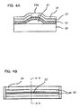
- the line heater 11 is configured as illustrated in FIG. 4.
- FIG. 4A is a sectional view taken along a line A-A of FIG. 4B.
- FIG. 4B is a plan view, partly broken away, of the line heater 11, taken from above FIG. 4A. It is to be noted that the upper part of FIG. 4A corresponds to the lower part of FIG. 1.
- the line heater 11 is configured as a thin-film type line heater having laminated on its heat dissipation substrate 20, a heat-resisting layer 21, a heat generating resistor 22, electrodes 23, and a wear-resisting layer 24.
- the heat-resisting layer 21 is formed as a convex shape of portion on and at the central part of the heat-dissipation substrate 20.
- the heat generating resistor 22, etc. laminated on it are formed in the way that they rise at the center.
- the electrodes 23 are disposed so that they clamp the apex portion of that rise of the heat generating resistor 22.
- Aportion of the wear-resisting layer 24 corresponding to the spacing between the electrodes 23 functions as a heat generating portion 24a.
- the heat generating portion 24a extends over a length corresponding to the plurality of heat generating portions 6a, ... 6a of the thermal head. In this embodiment, the heat generating portion 24a extends over a length corresponding to the entire width of the thermal head.
- the heat dissipation substrate 20 for example, ceramics is used.
- the heat-resisting layer 21 for example, glass is used.
- the heat generating resistor 22 for example, Ta 2 N, W, Cr, Ni-Cr, SnO 2 , etc. are used.
- the heat generating resistor 22 is formed, like a line, using a thin-film configuration technique such as vacuum deposition, CVD, sputtering, etc.
- the electrode 23, for example, Al is used.
- the wear-resisting layer 24 for example, Ta 2 O 3 , Si 3 N 4 , SiC, etc are used.
- the wear-resisting layer 24 may be formed into a two-layer structure.
- the image-receiving paper 100 has an image-receiving layer 100a on its upper surface.
- the transfer film 50 has sequentially provided therein in a direction counter to the feeding direction of paper, for example, ink areas of Yellow (Y) , Magenta (M) , and Cyan (C) and an area of overprint (OP) layer.
- the printer 1 having the above-described configuration will now be explained.
- the image-receiving paper 100 is conveyed to the area under the thermal head 6 by the platen roller 4, the image-receiving paper 100, along with the transfer film 50, is pressed between the platen roller 4 and the thermal head 6, in such a way that it is clamped between the both.
- the Y, M, and C inks are adhered to the image-receiving layer 100a of the image-receiving paper 100 by heat-generation controlling each heat generating portion 6a, ... 6a.
- the portion corresponding to a 1 line of pixels is formed.
- the printer 1 transfers the OP layer onto the 1 line of pixel image by heat-generation controlling the heat generating portions 6a, ... 6a.
- the OP layer has a protection layer 53 and adhesion layer 54.
- a release layer 52, the protection layer 53, and the adhesion layer 54 are laminated on a base material 51 of the transfer film 50 in this order so that the OP layer is provided on the transfer film 50.
- the protection layer 53 and adhesion layer 54 are transferred onto the image-receiving paper 100.
- the upper part of FIG. 5A corresponds to the lower part of FIG. 1.
- the release layer 52 may not be provided.
- the printer 1 intermittently conveys the image-receiving paper 100, by the platen roller 4, by the portion thereof corresponding to the 1 line of pixels. Further, by repeatedly performing transfer of the 1 line of pixel ink and protection layer 53, the printer 1 forms images on a predetermined area 100b and simultaneously transfers the protection layer 53 on those images.
- the heat generating portions 6a, ... 6a are provided in space intervals from one another, the heating temperatures taken in the direction that goes along the thermal head 6 are not uniform. Therefore, concavo-convex portions are formed in the width direction of the protection layer 53 that has been transferred to the image-receiving paper 100. Further, since the protection layer 53 is transferred while the image-receiving paper 100 is shifted relative to the thermal head by the quantity corresponding to one line, the protection layer 53 also has concavo-convex portions formed in the feeding direction, as well, of the paper. Accordingly, the protection layer 53 is formed like a mat. Therefore, because of irregular reflection of that surface, it results that the image-receiving paper 100 has its luster lost.
- the image-receiving paper 100 When the image-receiving paper 100 is conveyed to the area under the line heater 11, the image-receiving paper 100 is pressed between the platen roller 10 and the line heater 11 in such a way that it is clamped between the both.
- the printer 1 causes the line heater 11 to generate heat until the temperature thereof becomes a softening temperature of the protection layer 53 and, conveys the image-receiving paper 100 using the platen roller 10. For this reason, the convex portions of the protection layer 53 are pressed while they are being heated by the heat generating portion 24a, with the result that the convex portions that have been softened are leveled.
- the concavo-convex portions of the protection layer 53 are made smooth, thereby it is possible to improve the luster of the post-printing image-receiving paper 100.
- the printer 1 can suitably be used for forming a print matter like a photograph and can also be applied to a photographic sealing machine as well.
- the temperature of the heat generated from the line heater is set to, for example, 140°C to 150°C while the conveying speed of the platen roller 10 is set to 1000mm/min.
- the conveying speed of the platen roller 10 and the generated-heat temperature of the heat generating portion 24a may each be fixed or made variable.
- the conveying speed of the platen roller 10 may be set to the same value as that of the conveying speed of the platen roller 4 or may be set to a different value from that of the conveying speed of the platen roller 4.
- the generated-heat temperature of the heat generating portion 24a may be set to a temperature that is higher than the temperature at which the protection layer 53 begins to soften, so that the protection layer 53 can be softened even in a short period of time.
- the protection layer 53 various kinds of material can be used. By imparting releasability to the protection layer 53, the protection layer 53 may be made easily separable from the heat generating portion 24a when mutual rub occurs between the heat generating portion 24a and the protection layer 53. Because of this, the accuracy of smoothing may be made high.
- an ordinary type of lubricant such as silicone oil, metal soap, or phosphate ester
- an ordinary type of resin such as polymethacrylic acid methyl
- resin material thathas releasability in itself, such as silicone resin may be used in independent form.
- silicone resin and lubricant may be used in combined form.
- the material having at-heating releasability that exhibits releasability at the temperature at which the protection layer softens may be used.
- the printing method is not limited to that in which sublimation heat-transfer is carried out. It may be the one in which melt heat-transfer is carried out, or the one in which heat-sensitive recording paper is rendered a color. It may be any method in which the protection layer is heated by the thermal head, thereby the concavo-convex portions are formed.
- the heat generating portion 24a of the line heater 11 is not limited to the one that continuously extends over the entire width of the image-receiving paper 100. If that heat generating portion continuously extends over a length corresponding to some pieces of the heat generating portions 6a of the thermal head 6, it is possible to make the image-receiving paper 100 smooth.
- the line heater 11 is not limited to the one that is disposed so that it may intersect the feeding direction of paper at a right angle with respect thereto, and the line heater 11 may be disposed along the direction that is in coincidence with the feeding direction of paper.
- the line heater 11 is not limited to a thin-film type and a thick-film type of line heater may be used as that line heater 11.
- the relative movement between the image-receiving paper 100 and line heater 11 may be realized by moving the line heater 11, or by moving both of the image-receiving paper 100 and the line heater 11.
- the line heater is provided therein a single heat generating portion that has a length corresponding to a plurality of heat generating portions of the thermal head, it is possible, by disposing the line heater so that it may contact with the protective layer and, while causing generation of heat from its heat generating portion, relatively moving the line heater and the printing paper, to soften, flatten, and level the concavo-convex portions stated above. Accordingly, it is possible to make smooth the surface of the printing paper and therefore improve the luster of the printing paper.
Landscapes
- Physics & Mathematics (AREA)
- Geometry (AREA)
- Electronic Switches (AREA)
Abstract
Description
- The present invention relates to a method of smoothing the surface of printingpaper, asmoothingapparatus, andaprinter with the smoothing apparatus.
- In printing by heat transfer, a protection layer for protecting an ink layer is also transferred along with the ink layer. Ordinarily, the protection layer is transferred by the heat of a thermal head. Further, a technique for transferring the protection layer by the heat of a line heater is also known (described in Granted Japanese Patent No. 3314980).
- Incidentally, a technique for re-heating the ink layer after transferred for the purpose of making the ink monomolecular and thereby increasing its resistance to light is also known (described in Japanese Patent Application Laid-Open No. 5-69678). For this re-heating, a heating roller is used.
- However, if the protection layer is transferredby a thermal head, since the thermal head is formed by arraying a plurality of heat generating portions corresponding to the pixels, the protection layer comes to have portions therein that are located at the heat generating portions and have portions therein that are locatedbetweentheheat generatingportions. For this reason, there are the problems such that the heat applied to the protection layer is not uniform, and thus concavo-convex portions occur in the protection layer and, therefore, the luster was lost.
- Thereupon, the present invention has an object to provide a method capable of smoothing the surface of printing paper formed by a thermal head.
- Hereafter, the present invention will be explained.
- In order to achieve the above object, one aspect of the present invention provides a method of smoothing a surface of printing paper, characterized by smoothing a protection layer formed on images of printing paper by heat of a thermal head having a plurality of heat generating portions arrayed apart from each other, the method comprising the steps of: disposing a line heater having a heat generating portion that continuously extends over a length corresponding to the plurality of heat generating portions of the thermal head, so that the heat generating portion may contact with the protection layer; and relatively moving the line heater and the printing paper, while causing generation of heat from the heat generating portion of the line heater.
- As described above, when the protection layer is formed by the thermal head, since this thermal head is discontinuously provided therein the heat generating portions, the heat applied to the protection layer is not uniform. Thus, concavo-convex portions occur on the surface of the protection layer. On the other hand, the line heater is provided therein a single heat generating portion that has a length corresponding to the plurality of heat generating portions of the thermal head. Therefore, it is possible, by disposing the line heater so as to contact with the protection layer and, while causing generation of heat from its heat generating portion, relatively moving the line heater and printing paper, to soften, flatten, and level those concavo-convex portions. Accordingly, it is possible to make smooth the surface of the printingpaper and therefore improve the luster of the printing paper. Furthermore, since using the line heater, comparing to the case where a roller for heating is used, there are various merits including that of enabling faster generation of heat, that of enabling lessening the power consumption, that of enabling miniaturizing the heater, and that of enabling making narrow the area of its contacting with the printing paper and thereby increasing the pressure of pressing that paper.
- In the method of smoothing printing paper according to the present invention, releasability may be imparted to the protection layer. In this case, when mutual rub occurs between the heat generating portion of the line heater and the protection layer, since that protection layer is easily released from that heat generating portion, it is possible to more increase the accuracy of smoothing.
- In order to achieve the above object, another aspect of the present invention provides an apparatus for smoothing a surface of printing paper, characterized by smoothing a protection layer formed on images of printing paper by heat of a thermal head having arrayed therein at space intervals from one another a plurality of heat generatingportions , the apparatus comprising: a line heater having a heat generating portion that continuously extends over a length corresponding to the plurality of heat generating portions of the thermal head and that is disposed so that the heat generating portion may contact with the protection layer; and a device for relatively moves the line heater and the printing paper. According to the smoothing apparatus of the present invention, it is possible to realize the above-described method of smoothing.
- In order to achieve the above object, still another aspect of the present invention provides a printer characterized by forming a protection layer on images of printing paper by heat of a thermal head having a plurality of heat generating portions arrayed apart from each other, the printer comprising: a line heater that, on a downstream side of the thermal head in the feeding direction of the printing paper, has a heat generating portion that continuously extends over a length corresponding to the plurality of heat generating portions of the thermal head, the heat generating portion being disposed so as to contact with the protection layer. According to the printer of the present invention, it is possible to smooth the surface of printing paper by us ing the above smoothingmethod and thereby obtain the printing paper, the luster of which has been improved.
- In the printer according to the present invention, the line heater may be provided in such a way as to extend over the entire width of the printing paper. In this case, if only once causing the printing paper to pass on the line heater, that paper can be made smooth. Therefore, it is possible to quickly make that paper smooth. In addition, since the line heater extends in a direction perpendicular to the direction in which the paper is fed, simply feeding the printing paper out along the feeding direction thereof enables smoothing the printing pater. Thus, the configuration of the printer can be simplified.
-
- FIG. 1 is a side view illustrating the outline of a printer according to an embodiment of the present invention;
- FIG. 2 is an upper surface view illustrating the outline of the printer illustrated in FIG. 1;
- FIGS. 3A and 3B are views illustrating respective heat generating portions of a thermal head and line heater of the printer illustrated in FIG. 1;
- FIGS. 4A and 4B are views illustrating configurations of the line heater of the printer illustrated in FIG. 1; and
- FIGS. 5A and 5B are views illustrating configurations of a transfer film and image-receiving paper.
-
- FIGS. 1 and 2 illustrate the outline of a printer according to an embodiment of a method of smoothing of the present invention. FIG. 1 is a side view, and FIG. 2 is an upper surface view. The
printer 1 is configured as a sublimation heat-transfer type printer that heat-transfers the ink of atransfer film 50 onto an image-receiving paper (printing paper) 100 to form an image. The image-receivingpaper 100 is attached to theprinter 1 in the state where it is wound like, for example, a roll and it is drawn out from the roll by the quantity necessary for printing. Theprinter 1 has aprinting section 2 andsmoothing section 3 on a conveyance passage for the image-receivingpaper 100 drawn out from the roll. - The
printing section 2 is provided therein aplaten roll 4 that conveys the image-receivingpaper 100 while it supports this image-receivingpaper 100, afeed roll 5 that has wound therearound a not-already-used heat-transfer film 50, athermal head 6 that heats the heat-transfer film 50 that has been delivered from thefeed roll 5, and a wind-uproll 7 that takes up the heat-transfer film 50 that has been heated by thethermal head 6. On the underside of thethermal head 6, as conceptually shown in FIG. 3A, a plurality ofheat generating portions 6a, ... 6a are arranged apart from each other. The heat generatingportions 6a, ... 6a correspond to the pixels of an original printing matter and their temperatures are made controllable for each of theheatgeneratingportions 6a. The heat generatingportions 6a ... 6a are provided, for example, 12 pieces per 1mm. For thethermal head 6, any known structure of thermal head can be used, and at each of the space between adjacent two of the heat generatingportions 6a ... 6a, a notch may be provided or a separate member such as a heat-insulating material may be provided. - The
smoothing section 3 illustrated in FIGS. 1 and 2 is provided, for example, at a discharging part of the printerl. In thesmoothing section 3, there are provided aplaten roll 10 that conveys the image-receivingpaper 100 while it supports thatpaper 100 and aline heater 11 that heats the image-receivingpaper 100. Theplaten roll 10 andline heater 11 are disposed so as to be in a direction perpendicular to the direction in which the paper is fed, the direction being indicated by the arrow y, and are extended over the entire width of the image-receivingpaper 100. Also, theplaten roll 10 andline heater 11 are disposed so that they can press the image-receivingpaper 100 in such a manner as to sandwich the image-receivingpaper 100 with a predetermined level of pressure. For example, they can press the image-receivingpaper 100 under a pressure that is the same extent of 20 to 30N as the printing pressure of a general thermal head. Incidentally, theplaten roll 10 orline heater 11 may be attached so that its vertical position can be controlled by a driving device such as a motor so that its pressure of pressing the image-receivingpaper 100 can be adjusted. Alternatively, it may be attached so that it can be rocked via, for example, an elastic member so that it can mechanically press the image-receivingpaper 100 under a predetermined level of pressure. Alternatively, theplaten roll 10 andline heater 11 may be attached so that each of their vertical positions may be fixed to a fixed position. - The
line heater 11 is configured as illustrated in FIG. 4. FIG. 4A is a sectional view taken along a line A-A of FIG. 4B. FIG. 4B is a plan view, partly broken away, of theline heater 11, taken from above FIG. 4A. It is to be noted that the upper part of FIG. 4A corresponds to the lower part of FIG. 1. Theline heater 11 is configured as a thin-film type line heater having laminated on itsheat dissipation substrate 20, a heat-resistinglayer 21, aheat generating resistor 22,electrodes 23, and a wear-resistinglayer 24. The heat-resistinglayer 21 is formed as a convex shape of portion on and at the central part of the heat-dissipation substrate 20. Accordingly, theheat generating resistor 22, etc. laminated on it are formed in the way that they rise at the center. Theelectrodes 23 are disposed so that they clamp the apex portion of that rise of theheat generating resistor 22. Aportion of the wear-resistinglayer 24 corresponding to the spacing between theelectrodes 23 functions as aheat generating portion 24a. Theheat generating portion 24a, as illustrated in FIG. 3B, extends over a length corresponding to the plurality ofheat generating portions 6a, ... 6a of the thermal head. In this embodiment, theheat generating portion 24a extends over a length corresponding to the entire width of the thermal head. - For the
heat dissipation substrate 20, for example, ceramics is used. For the heat-resistinglayer 21, for example, glass is used. For theheat generating resistor 22, for example, Ta2N, W, Cr, Ni-Cr, SnO2, etc. are used. Theheat generating resistor 22 is formed, like a line, using a thin-film configuration technique such as vacuum deposition, CVD, sputtering, etc. For theelectrode 23, for example, Al is used. For the wear-resistinglayer 24, for example, Ta2O3, Si3N4, SiC, etc are used. Furthermore, by providing on theelectrode 23 side a layer that consists of SiO2 or the like and that has an oxidation-resisting layer, the wear-resistinglayer 24 may be formed into a two-layer structure. - Supplying an electric current to the
heat generating resistor 22 via the intermediary of theelectrodes 23 causes heat to be generated at the portion clamped between the left andright electrodes 23. Accordingly, it is possible to heat the paper-receivingpaper 100 via theheat generating portion 24a. About theline heater 11, as the heat-resistinglayer 21 located under the heat generating portion is formed thickly, the leakage of the heat to the heat-dissipation substrate 20 side is less, and the efficient heating of the image-receivingpaper 100 is possible. Incidentally, by detecting the temperature by disposing a thermistor above or below the heat-dissipation substrate 20 the temperature of theline heater 11 may be made accurately controllable. - In FIG. 1, the image-receiving
paper 100 has an image-receivinglayer 100a on its upper surface. Thetransfer film 50 has sequentially provided therein in a direction counter to the feeding direction of paper, for example, ink areas of Yellow (Y) , Magenta (M) , and Cyan (C) and an area of overprint (OP) layer. - The operation of the
printer 1 having the above-described configuration will now be explained. When the image-receivingpaper 100 is conveyed to the area under thethermal head 6 by theplaten roller 4, the image-receivingpaper 100, along with thetransfer film 50, is pressed between theplaten roller 4 and thethermal head 6, in such a way that it is clamped between the both. The Y, M, and C inks are adhered to the image-receivinglayer 100a of the image-receivingpaper 100 by heat-generation controlling eachheat generating portion 6a, ... 6a. As a result of this, of the images that plan to be printed, the portion corresponding to a 1 line of pixels is formed. - Thereafter, the
printer 1 transfers the OP layer onto the 1 line of pixel image by heat-generation controlling theheat generating portions 6a, ... 6a. As illustrated in FIG. 5A, the OP layer has aprotection layer 53 andadhesion layer 54. Further, arelease layer 52, theprotection layer 53, and theadhesion layer 54 are laminated on abase material 51 of thetransfer film 50 in this order so that the OP layer is provided on thetransfer film 50. Accordingly, as illustrated in FIG. 5B, theprotection layer 53 andadhesion layer 54 are transferred onto the image-receivingpaper 100. Incidentally, the upper part of FIG. 5A corresponds to the lower part of FIG. 1. Also, therelease layer 52 may not be provided. - The
printer 1 intermittently conveys the image-receivingpaper 100, by theplaten roller 4, by the portion thereof corresponding to the 1 line of pixels. Further, by repeatedly performing transfer of the 1 line of pixel ink andprotection layer 53, theprinter 1 forms images on apredetermined area 100b and simultaneously transfers theprotection layer 53 on those images. - Since the
heat generating portions 6a, ... 6a are provided in space intervals from one another, the heating temperatures taken in the direction that goes along thethermal head 6 are not uniform. Therefore, concavo-convex portions are formed in the width direction of theprotection layer 53 that has been transferred to the image-receivingpaper 100. Further, since theprotection layer 53 is transferred while the image-receivingpaper 100 is shifted relative to the thermal head by the quantity corresponding to one line, theprotection layer 53 also has concavo-convex portions formed in the feeding direction, as well, of the paper. Accordingly, theprotection layer 53 is formed like a mat. Therefore, because of irregular reflection of that surface, it results that the image-receivingpaper 100 has its luster lost. - When the image-receiving
paper 100 is conveyed to the area under theline heater 11, the image-receivingpaper 100 is pressed between theplaten roller 10 and theline heater 11 in such a way that it is clamped between the both. Theprinter 1 causes theline heater 11 to generate heat until the temperature thereof becomes a softening temperature of theprotection layer 53 and, conveys the image-receivingpaper 100 using theplaten roller 10. For this reason, the convex portions of theprotection layer 53 are pressed while they are being heated by theheat generating portion 24a, with the result that the convex portions that have been softened are leveled. Accordingly, the concavo-convex portions of theprotection layer 53 are made smooth, thereby it is possible to improve the luster of the post-printing image-receivingpaper 100. Theprinter 1 can suitably be used for forming a print matter like a photograph and can also be applied to a photographic sealing machine as well. - The temperature of the heat generated from the line heater is set to, for example, 140°C to 150°C while the conveying speed of the
platen roller 10 is set to 1000mm/min. The conveying speed of theplaten roller 10 and the generated-heat temperature of theheat generating portion 24a may each be fixed or made variable. The conveying speed of theplaten roller 10 may be set to the same value as that of the conveying speed of theplaten roller 4 or may be set to a different value from that of the conveying speed of theplaten roller 4. When the conveying speed of theplaten roller 10 is fast, the generated-heat temperature of theheat generating portion 24a may be set to a temperature that is higher than the temperature at which theprotection layer 53 begins to soften, so that theprotection layer 53 can be softened even in a short period of time. - For the
protection layer 53, various kinds of material can be used. By imparting releasability to theprotection layer 53, theprotection layer 53 may be made easily separable from theheat generating portion 24a when mutual rub occurs between theheat generating portion 24a and theprotection layer 53. Because of this, the accuracy of smoothing may be made high. When imparting releasability to the protection layer, an ordinary type of lubricant such as silicone oil, metal soap, or phosphate ester, and an ordinary type of resin such as polymethacrylic acid methyl may be used in combined form. Alternatively, resin material thathas releasability in itself, such as silicone resin, may be used in independent form. Alternatively, silicone resin and lubricant may be used in combined form. Also, the material having at-heating releasability that exhibits releasability at the temperature at which the protection layer softens may be used. - The present invention is not limited to the above-described embodiment and permits various changes or modifications to be made so long as they are substantially the same as the technical idea of the invention.
- The printing method is not limited to that in which sublimation heat-transfer is carried out. It may be the one in which melt heat-transfer is carried out, or the one in which heat-sensitive recording paper is rendered a color. It may be any method in which the protection layer is heated by the thermal head, thereby the concavo-convex portions are formed.
- The
heat generating portion 24a of theline heater 11 is not limited to the one that continuously extends over the entire width of the image-receivingpaper 100. If that heat generating portion continuously extends over a length corresponding to some pieces of theheat generating portions 6a of thethermal head 6, it is possible to make the image-receivingpaper 100 smooth. Theline heater 11 is not limited to the one that is disposed so that it may intersect the feeding direction of paper at a right angle with respect thereto, and theline heater 11 may be disposed along the direction that is in coincidence with the feeding direction of paper. Theline heater 11 is not limited to a thin-film type and a thick-film type of line heater may be used as thatline heater 11. - The relative movement between the image-receiving
paper 100 andline heater 11 may be realized by moving theline heater 11, or by moving both of the image-receivingpaper 100 and theline heater 11. - According to the present invention, since the line heater is provided therein a single heat generating portion that has a length corresponding to a plurality of heat generating portions of the thermal head, it is possible, by disposing the line heater so that it may contact with the protective layer and, while causing generation of heat from its heat generating portion, relatively moving the line heater and the printing paper, to soften, flatten, and level the concavo-convex portions stated above. Accordingly, it is possible to make smooth the surface of the printing paper and therefore improve the luster of the printing paper. Furthermore, since using the line heater, comparing to the case where the roller for heating is used, there are various merits including that of enabling faster generation of heat, that of enabling lessening the power consumption, that of enabling miniaturizing the heater, and that of enabling making narrow the area of its being contacted with the printing paper and thereby increasing the pressure of pressing that paper.
Claims (5)
- A method of smoothing a surface of printing paper (100) , characterized by smoothing a protection layer (53) formed on images of printing paper (100) by heat of a thermal head (6) having a plurality of heat generating portions (6a, ...6a) arranged apart from each other, the method comprising the steps of:disposing a line heater (11) having a heat generating portion (24a) that continuously extends over a length corresponding to the plurality of heat generating portions (6a, ...6a) of the thermal head (6) , so that the heat generating portion (24a) may contact with the protection layer (53); andrelatively moving the line heater (11) and the printing paper (100), while causing generation of heat from the heat generating portion (24a) of the line heater (11).
- The method of smoothing the surface of printing paper (100) according to claim 1, wherein releasability is imparted to the protection layer (53).
- An apparatus (3) for smoothing a surface of printing paper (100) , characterized by smoothing a protection layer (53) formed on images of printing paper (100) by heat of a thermal head (6) havingapluralityofheatgeneratingportions (6a, ... 6a) arrayed apart from each other, the apparatus (3) comprising:a line heater (11) having a heat generating portion (24a) that continuously extends over a length corresponding to the plurality of heat generating portions (6a, ...6a) of the thermal head (6) and that is disposed so that the heat generating portion (24a) may contact with the protection layer (53); anda device (10) for relatively moving the line heater (11) and the printing paper (100).
- A printer (1) characterized by forming a protection layer (53) on images of printing paper (100) by heat of a thermal head (6) having a plurality of heat generating portions (6a, ...6a) arrayed apart form each other, the printer (1) comprising:a line heater (11) that, on a downstream side of the thermal head (6) in the feeding direction of the printing paper (100) , has a heat generating portion (24a) that continuously extends over a length corresponding to the plurality of heat generating portions (6a, ...6a) of the thermal head (6) , the heat generating portion (24a) being disposed so as to contact with the protection layer (53).
- The printer (1) according to claim 4, wherein the line heater (11) is provided so as to extend over an entire width of the printing paper (100).
Applications Claiming Priority (2)
| Application Number | Priority Date | Filing Date | Title |
|---|---|---|---|
| JP2002364619 | 2002-12-17 | ||
| JP2002364619A JP3784366B2 (en) | 2002-12-17 | 2002-12-17 | Method for smoothing the surface of photographic paper |
Publications (2)
| Publication Number | Publication Date |
|---|---|
| EP1431048A1 true EP1431048A1 (en) | 2004-06-23 |
| EP1431048B1 EP1431048B1 (en) | 2008-12-03 |
Family
ID=32376230
Family Applications (1)
| Application Number | Title | Priority Date | Filing Date |
|---|---|---|---|
| EP03257887A Expired - Lifetime EP1431048B1 (en) | 2002-12-17 | 2003-12-16 | Method of smoothing surface of printing paper, smoothing apparatus, and printer with the smoothing apparatus |
Country Status (4)
| Country | Link |
|---|---|
| US (1) | US7009631B2 (en) |
| EP (1) | EP1431048B1 (en) |
| JP (1) | JP3784366B2 (en) |
| DE (1) | DE60325007D1 (en) |
Families Citing this family (7)
| Publication number | Priority date | Publication date | Assignee | Title |
|---|---|---|---|---|
| US7113198B2 (en) * | 2004-09-08 | 2006-09-26 | Pitney Bowes Inc. | Method and system for creation of secure documents using digital embossing of thermal media with thermal print heads |
| JP4544111B2 (en) * | 2005-09-16 | 2010-09-15 | ソニー株式会社 | Image forming apparatus and image forming method |
| JP5056430B2 (en) * | 2007-08-03 | 2012-10-24 | ソニー株式会社 | Image forming method, image forming apparatus, surface modification sheet, thermal transfer sheet |
| JP5223317B2 (en) * | 2007-12-05 | 2013-06-26 | ソニー株式会社 | Printer device and laminating method |
| JP5151496B2 (en) * | 2008-01-17 | 2013-02-27 | ソニー株式会社 | Image forming apparatus and modified sheet cartridge used therefor |
| CN201503666U (en) * | 2009-07-28 | 2010-06-09 | 东莞植富商标印制有限公司 | Heat-transfer electronic radio frequency identification label |
| JP2011167948A (en) * | 2010-02-19 | 2011-09-01 | Mitsubishi Electric Corp | Thermal transfer recorder |
Citations (5)
| Publication number | Priority date | Publication date | Assignee | Title |
|---|---|---|---|---|
| JPH0569678A (en) * | 1991-09-17 | 1993-03-23 | Matsushita Electric Ind Co Ltd | Thermal transfer recording and its device |
| JPH06336043A (en) * | 1993-05-28 | 1994-12-06 | Dainippon Printing Co Ltd | Heat transfer recording method and device thereof |
| JPH08328404A (en) * | 1995-05-31 | 1996-12-13 | Kyocera Corp | Toner fixing heater |
| JPH09193433A (en) * | 1996-01-18 | 1997-07-29 | Rohm Co Ltd | Protective film on heating resistor |
| JPH10291332A (en) * | 1997-02-19 | 1998-11-04 | Fuji Photo Film Co Ltd | Color thermosensitive color printing method and apparatus, and smoothing processing apparatus |
Family Cites Families (7)
| Publication number | Priority date | Publication date | Assignee | Title |
|---|---|---|---|---|
| JPS59215885A (en) * | 1983-05-24 | 1984-12-05 | Ricoh Co Ltd | Image hardening processing method |
| JPH04103360A (en) * | 1990-08-23 | 1992-04-06 | Victor Co Of Japan Ltd | Transfer method of heat melting transparent binder |
| JP3033486B2 (en) * | 1995-06-30 | 2000-04-17 | 富士ゼロックス株式会社 | Fixing method and apparatus |
| US5851720A (en) * | 1995-11-14 | 1998-12-22 | Sony Corporation | Transfer material for use in thermal transfer and method of forming thermal transfer images |
| JPH1086420A (en) | 1996-09-18 | 1998-04-07 | Dainippon Printing Co Ltd | Method and apparatus for surface smoothing treatment of heat transfer target by thermal transfer recording method |
| JP2002113958A (en) | 2000-10-12 | 2002-04-16 | Konica Corp | Thermal transfer recording method and printed matter |
| US6984424B2 (en) * | 2002-03-01 | 2006-01-10 | Dai Nippon Printing Co., Ltd. | Thermally transferable image protective sheet, method for protective layer formation, and record produced by said method |
-
2002
- 2002-12-17 JP JP2002364619A patent/JP3784366B2/en not_active Expired - Fee Related
-
2003
- 2003-12-16 US US10/736,828 patent/US7009631B2/en not_active Expired - Lifetime
- 2003-12-16 EP EP03257887A patent/EP1431048B1/en not_active Expired - Lifetime
- 2003-12-16 DE DE60325007T patent/DE60325007D1/en not_active Expired - Lifetime
Patent Citations (5)
| Publication number | Priority date | Publication date | Assignee | Title |
|---|---|---|---|---|
| JPH0569678A (en) * | 1991-09-17 | 1993-03-23 | Matsushita Electric Ind Co Ltd | Thermal transfer recording and its device |
| JPH06336043A (en) * | 1993-05-28 | 1994-12-06 | Dainippon Printing Co Ltd | Heat transfer recording method and device thereof |
| JPH08328404A (en) * | 1995-05-31 | 1996-12-13 | Kyocera Corp | Toner fixing heater |
| JPH09193433A (en) * | 1996-01-18 | 1997-07-29 | Rohm Co Ltd | Protective film on heating resistor |
| JPH10291332A (en) * | 1997-02-19 | 1998-11-04 | Fuji Photo Film Co Ltd | Color thermosensitive color printing method and apparatus, and smoothing processing apparatus |
Non-Patent Citations (5)
| Title |
|---|
| PATENT ABSTRACTS OF JAPAN vol. 017, no. 389 (M - 1449) 21 July 1993 (1993-07-21) * |
| PATENT ABSTRACTS OF JAPAN vol. 1995, no. 03 28 April 1995 (1995-04-28) * |
| PATENT ABSTRACTS OF JAPAN vol. 1997, no. 04 30 April 1997 (1997-04-30) * |
| PATENT ABSTRACTS OF JAPAN vol. 1997, no. 11 28 November 1997 (1997-11-28) * |
| PATENT ABSTRACTS OF JAPAN vol. 1999, no. 02 26 February 1999 (1999-02-26) * |
Also Published As
| Publication number | Publication date |
|---|---|
| JP3784366B2 (en) | 2006-06-07 |
| JP2004195711A (en) | 2004-07-15 |
| DE60325007D1 (en) | 2009-01-15 |
| EP1431048B1 (en) | 2008-12-03 |
| US20040165052A1 (en) | 2004-08-26 |
| US7009631B2 (en) | 2006-03-07 |
Similar Documents
| Publication | Publication Date | Title |
|---|---|---|
| US6390617B1 (en) | Image forming apparatus | |
| KR0136076B1 (en) | Fusing Device and Image Forming Device With The Same | |
| KR101491523B1 (en) | Method and apparatus for forming image, surface-property-modifying sheet, and thermal transfer sheet | |
| US8641163B2 (en) | Temperature leveling roller and pressure nip assembly | |
| US7009631B2 (en) | Method of smoothing surface of printing paper, smoothing apparatus and printer with the smoothing apparatus | |
| CN100455444C (en) | Method and apparatus for controlling printing in a thermal printer | |
| CN100567007C (en) | thermal print head | |
| JPH0679889A (en) | Thermal printer | |
| US8668318B2 (en) | System and method for spreading ink on a media web | |
| JPH09511459A (en) | Thermoelectric printer for transferring ink to recording media | |
| JP2003145846A (en) | Printer | |
| JP3314980B2 (en) | Thermal transfer recording method and apparatus | |
| JPH1178090A (en) | Thermal color printing method, thermal head and printer | |
| JP4113864B2 (en) | Thermal transfer recording method and thermal transfer recording apparatus | |
| JP4584882B2 (en) | Thick film thermal print head | |
| JP7307894B2 (en) | THERMAL TRANSFER SYSTEM AND THERMAL TRANSFER METHOD | |
| JP2002154724A (en) | Transfer device and method for manufacturing transferred material | |
| EP1520714A2 (en) | Thermal transfer recording method and apparatus | |
| JP2000255089A (en) | Contact type recording head and image forming apparatus using the same | |
| JPH0863016A (en) | Fixing device | |
| US20060232656A1 (en) | Thermal printer, print head, printing method and substrate for use therewith | |
| US4639742A (en) | Method and apparatus for printing an image | |
| JP3765766B2 (en) | Thermal head | |
| JP2012013868A (en) | Heating apparatus | |
| JPH0480049A (en) | Thermal head |
Legal Events
| Date | Code | Title | Description |
|---|---|---|---|
| PUAI | Public reference made under article 153(3) epc to a published international application that has entered the european phase |
Free format text: ORIGINAL CODE: 0009012 |
|
| AK | Designated contracting states |
Kind code of ref document: A1 Designated state(s): AT BE BG CH CY CZ DE DK EE ES FI FR GB GR HU IE IT LI LU MC NL PT RO SE SI SK TR |
|
| AX | Request for extension of the european patent |
Extension state: AL LT LV MK |
|
| 17P | Request for examination filed |
Effective date: 20040807 |
|
| AKX | Designation fees paid |
Designated state(s): DE FR GB |
|
| 17Q | First examination report despatched |
Effective date: 20070321 |
|
| GRAP | Despatch of communication of intention to grant a patent |
Free format text: ORIGINAL CODE: EPIDOSNIGR1 |
|
| GRAS | Grant fee paid |
Free format text: ORIGINAL CODE: EPIDOSNIGR3 |
|
| GRAA | (expected) grant |
Free format text: ORIGINAL CODE: 0009210 |
|
| AK | Designated contracting states |
Kind code of ref document: B1 Designated state(s): DE FR GB |
|
| REG | Reference to a national code |
Ref country code: GB Ref legal event code: FG4D |
|
| REF | Corresponds to: |
Ref document number: 60325007 Country of ref document: DE Date of ref document: 20090115 Kind code of ref document: P |
|
| PLBE | No opposition filed within time limit |
Free format text: ORIGINAL CODE: 0009261 |
|
| STAA | Information on the status of an ep patent application or granted ep patent |
Free format text: STATUS: NO OPPOSITION FILED WITHIN TIME LIMIT |
|
| 26N | No opposition filed |
Effective date: 20090904 |
|
| REG | Reference to a national code |
Ref country code: FR Ref legal event code: PLFP Year of fee payment: 13 |
|
| REG | Reference to a national code |
Ref country code: FR Ref legal event code: PLFP Year of fee payment: 14 |
|
| REG | Reference to a national code |
Ref country code: FR Ref legal event code: PLFP Year of fee payment: 15 |
|
| PGFP | Annual fee paid to national office [announced via postgrant information from national office to epo] |
Ref country code: GB Payment date: 20201223 Year of fee payment: 18 Ref country code: DE Payment date: 20201211 Year of fee payment: 18 Ref country code: FR Payment date: 20201223 Year of fee payment: 18 |
|
| REG | Reference to a national code |
Ref country code: DE Ref legal event code: R119 Ref document number: 60325007 Country of ref document: DE |
|
| GBPC | Gb: european patent ceased through non-payment of renewal fee |
Effective date: 20211216 |
|
| PG25 | Lapsed in a contracting state [announced via postgrant information from national office to epo] |
Ref country code: GB Free format text: LAPSE BECAUSE OF NON-PAYMENT OF DUE FEES Effective date: 20211216 Ref country code: DE Free format text: LAPSE BECAUSE OF NON-PAYMENT OF DUE FEES Effective date: 20220701 |
|
| PG25 | Lapsed in a contracting state [announced via postgrant information from national office to epo] |
Ref country code: FR Free format text: LAPSE BECAUSE OF NON-PAYMENT OF DUE FEES Effective date: 20211231 |