EP1431047A1 - Tape printing device - Google Patents
Tape printing device Download PDFInfo
- Publication number
- EP1431047A1 EP1431047A1 EP03029089A EP03029089A EP1431047A1 EP 1431047 A1 EP1431047 A1 EP 1431047A1 EP 03029089 A EP03029089 A EP 03029089A EP 03029089 A EP03029089 A EP 03029089A EP 1431047 A1 EP1431047 A1 EP 1431047A1
- Authority
- EP
- European Patent Office
- Prior art keywords
- platen
- thermal head
- tape
- printing device
- tape printing
- Prior art date
- Legal status (The legal status is an assumption and is not a legal conclusion. Google has not performed a legal analysis and makes no representation as to the accuracy of the status listed.)
- Granted
Links
- 230000007246 mechanism Effects 0.000 claims abstract description 59
- 230000001105 regulatory effect Effects 0.000 claims description 64
- 229920005989 resin Polymers 0.000 claims description 28
- 239000011347 resin Substances 0.000 claims description 28
- 238000006073 displacement reaction Methods 0.000 claims description 3
- 238000003825 pressing Methods 0.000 description 28
- 238000005452 bending Methods 0.000 description 15
- 238000005192 partition Methods 0.000 description 15
- 230000006866 deterioration Effects 0.000 description 14
- 238000004519 manufacturing process Methods 0.000 description 10
- 238000005520 cutting process Methods 0.000 description 8
- 238000000465 moulding Methods 0.000 description 8
- 230000000994 depressogenic effect Effects 0.000 description 7
- 210000003811 finger Anatomy 0.000 description 5
- 238000007599 discharging Methods 0.000 description 4
- 229920003002 synthetic resin Polymers 0.000 description 4
- 239000000057 synthetic resin Substances 0.000 description 4
- 210000003813 thumb Anatomy 0.000 description 4
- 238000000034 method Methods 0.000 description 3
- 230000008569 process Effects 0.000 description 3
- 208000010727 head pressing Diseases 0.000 description 2
- 229910052751 metal Inorganic materials 0.000 description 2
- 239000002184 metal Substances 0.000 description 2
- 230000009467 reduction Effects 0.000 description 2
- 239000000853 adhesive Substances 0.000 description 1
- 230000001070 adhesive effect Effects 0.000 description 1
- 239000012790 adhesive layer Substances 0.000 description 1
- 229910052782 aluminium Inorganic materials 0.000 description 1
- XAGFODPZIPBFFR-UHFFFAOYSA-N aluminium Chemical compound [Al] XAGFODPZIPBFFR-UHFFFAOYSA-N 0.000 description 1
- 230000008859 change Effects 0.000 description 1
- 230000007423 decrease Effects 0.000 description 1
- 230000000881 depressing effect Effects 0.000 description 1
- 238000004512 die casting Methods 0.000 description 1
- 238000010438 heat treatment Methods 0.000 description 1
- 239000004973 liquid crystal related substance Substances 0.000 description 1
- 230000004048 modification Effects 0.000 description 1
- 238000012986 modification Methods 0.000 description 1
Images





Classifications
-
- B—PERFORMING OPERATIONS; TRANSPORTING
- B41—PRINTING; LINING MACHINES; TYPEWRITERS; STAMPS
- B41J—TYPEWRITERS; SELECTIVE PRINTING MECHANISMS, i.e. MECHANISMS PRINTING OTHERWISE THAN FROM A FORME; CORRECTION OF TYPOGRAPHICAL ERRORS
- B41J3/00—Typewriters or selective printing or marking mechanisms characterised by the purpose for which they are constructed
- B41J3/407—Typewriters or selective printing or marking mechanisms characterised by the purpose for which they are constructed for marking on special material
- B41J3/4075—Tape printers; Label printers
Definitions
- the present invention relates to a tape printing device that is configured such that a tape-form thermal recording medium (hereinafter, simply referred to as a tape) is pressed against a thermal head, letter/characters are printed on the tape, and a portion of the tape on which the letters/characters are printed is discharged to outside.
- a tape-form thermal recording medium hereinafter, simply referred to as a tape
- An example of the conventional tape printing devices is configured such that the tape is fed by a platen mechanism, which is movable between an operating position and a standby position in association with an attachment/detachment (i.e., attaching/detaching or opening/closing) of a back cover for covering a cassette holding section. Then, the tape is pressed against a thermal head by the platen. The. thermal head applies heat to the tape in accordance with print data to form letters/characters on the tape. Then, the printed portion of the tape is discharged outside.
- a tape printing device provided with a tape feeding mechanism, a thermal head for forming letters/characters on the tape, a platen that is retractably urged toward the thermal head is disclosed.
- the tape feeding mechanism, the thermal head and the platen are provided within a frame of a tape cassette holding section that accommodates a tape cassette.
- the platen is supported by a platen holder that is swingably supported by a holder shaft.
- the holder shaft stands on a base plate, and a head supporting member mounting a thermal head is disposed on the base plate. The position of the thermal head with respect to the platen is previously adjusted, and the base plate is secured on the frame by means of screws.
- United States Patent No. 5,839,840 discloses a tape printer having a platen mechanism which moves between an operable position and a retracted position in association with attachment/detachment of a back cover that covers a tape cassette holding section.
- a platen mechanism which moves between an operable position and a retracted position in association with attachment/detachment of a back cover that covers a tape cassette holding section.
- an engaging protrusion standing on an inner surface of the back cover is interposed between the movable platen and a fixed member, thereby the platen holder is swung toward the tape cassette until a portion of the tape is pressed against the thermal head by the platen.
- the head supporting member is typically made as a metal member, which is produced, for example, by aluminum die-casting.
- the head supporting member is secured on the base plate made of metal by means of screws, which raises a problem of increasing working processes and a manufacturing cost.
- the supporting plate provided in the tape mounting portion for supporting the thermal head is typically made of resin. Therefore, the supporting plate can be formed by a single resin molding process, and hence the manufacturing cost can be reduced.
- the present invention is advantageous in that the above-mentioned problem can be solved. That is, according to the invention, there is provided an improved tape printing device by which the thermal head mounting member on which the thermal head is to be mounted can be formed integrally with the cassette holding section in a single resin molding process to reduce the manufacturing cost. Further, the creep deformation of the thermal head mounting member can be prevented even if the tape printing device is stored or used in high temperature environment for a long time, and hence deterioration of tape printing quality can be prevented for a long time.
- a tape printing device that prints letters/characters on a tape-form thermal recording medium.
- the tape printing device is provided with a device body, a cassette holding section being formed in the device body to accommodate a tape cassette containing the tape-form recording medium, a cover member that covers the cassette holding section, a thermal head that applies heat to print letters/characters on the tape-form recording medium, a thermal head mounting portion formed on a bottom of the cassette holding section, the thermal head mounting portion including a plate-like member that protrudes from the bottom of the cassette holding section toward the cover member, the thermal head being attached to a side of the plate-like member, and a platen mechanism having a platen which faces the thermal head and is biased toward the thermal head.
- the thermal head mounting portion has an abutting member
- the cover member has a regulating member.
- the abutting member and the regulating member are configured such that the abutting member abuts the regulating member from a direction opposite to a direction in which the platen is biased toward the thermal head at least when the cover member covers the cassette holding section, deformation of the plate-like member urged by the platen being prevented as a displacement of the abutting member is prevented by the regulating member.
- the abutting member may include a protruded member protruding from a side end surface of the plate-like member.
- the regulating member is formed on an inner surface, which faces the thermal head mounting portion, of the cover member.
- the protruded member may be configured to have a substantially circular cross section along a plane perpendicular to a protruding direction of the protruded member.
- the protruded member has a substantially semicircular cross section along a plane perpendicular to a protruding direction of the protruded member, a convex surface of the protruded member facing the regulating member.
- the regulating member has a receiving portion that receives the protruded member, at least a portion of the receiving portion abutting the protruded member having a concave shape fitting to the shape of the protruded member.
- the platen mechanism is configured such that the platen moves between an operating position at which the platen is biased toward the thermal head and a standby position at which the platen is retracted from the operating position, and the abutting member faces the regulating member only when the platen is located at the operating position.
- the cover member is detachably attached to the body, and the platen mechanism is configured such that the platen moves between an operating position at which the platen is biased toward the thermal head and a standby position at which the platen is retracted from the operating position in association with attachment/detachment of the cover member with respect to the body.
- the platen mechanism has a moving mechanism that moves the platen between the operating position and the standby position
- the cover member has a protrusion portion formed on the inner surface of the cover member, the protrusion portion affecting the moving mechanism to move the platen.
- the abutting member may include a protruded member protruding from a side end surface of the plate-like member, and the regulating member may be formed on the inner surface, which faces the thermal head mounting portion, of the cover member.
- the cover member may include a pair of first ribs, the first ribs being formed on the inner surface of the cover member and extending from both sides of the regulating member.
- the cover member may include a pair of second ribs, the second ribs being formed on the inner surface of the cover member and extending from both sides of the protrusion portion.
- first ribs and the second ribs are joined between the regulating member and the protrusion portion.
- a distance between the regulating member and the protrusion portion may be determined such that the platen is urged against the thermal head at a predetermined force.
- the regulating member and the protrusion portion are formed integrally with the cover member.
- the thermal head mounting member and the cassette holding section are formed of resin.
- the cover member is made of resin.
- the thermal head mounting member is formed integrally with the cassette holding section.
- the platen mechanism may include a platen roller, and a biasing mechanism that biases the platen roller toward the thermal head, and the abutting portion may be formed on the cover member side end portion of the thermal head mounting member such that it faces a rotation axis of the platen roller when the platen mechanism is at the operating position.
- the platen mechanism may include a swinging mechanism that swings the platen mechanism from the operating position to the standby position about a fixed point
- the cover member has a protrusion portion formed on the inner surface, and the protrusion portion presses an outer side of the platen mechanism to move the platen mechanism from the standby position to the operating position against the swinging means.
- a tape printing device that prints letters/characters on a tape-form thermal recording medium
- a device body a cover member that covers detachably attached to the device body, a thermal head that applies heat to the tape-form recording medium so as to print letters/characters thereon
- a thermal head mounting portion provided to the device body, the thermal head mounting portion including a plate-like member that extends from the device body toward the cover member, the thermal head being attached to a side of the plate-like member, a platen mechanism having a platen which faces the thermal head and is biased toward the thermal head, and a supporting mechanism provided between the thermal head mounting portion and the cover member.
- the supporting mechanism is configured to support the plate-like member from a side opposite to the platen to prevent deformation of the plate-like member due to biasing force applied by the platen.
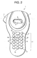
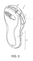
- the tape printing device 1 has a body 2 made of synthetic resin and a back cover 3 made of synthetic resin.
- the back cover 3 is detachably attached to the body 2 so that it covers the rear side, which is a side opposite to a front side that faces a user using the tape printing device 1, of the body 2.
- the tape printing device 1 is longer in an up and down direction in Fig. 2 than in a width direction (i.e., a right and left direction in Fig. 2).
- a substantially upper half of the body 2 in the longitudinal direction thereof is formed such that it has a rather round shape when viewed from the front (as shown in Fig. 2).
- a window 5 is opened at a substantially central area of the surface of the upper half of the body 2.
- the window 5 extends in right and left direction in Fig. 2.
- a liquid crystal display (LCD) 6 is provided at the window 5.
- LCD liquid crystal display
- a cutting lever 7 is provided on a left side of the upper half of the body 2.
- a thermal tape 9 that is printed and discharged from a tape discharging opening 8 (see Fig. 3) formed at an upper end of the tape printing device 1 can be cut by a cutter 10 (Fig. 5), which will be described later, by pressing the cutting lever 7 inwardly, with a thumb, for example.
- a substantially lower half of the body 2 in the longitudinal direction thereof, which constitute a gripping portion 11, is formed to have a width slightly smaller than the width of the upper half of the body 2, and corners at right and left sides thereof are rounded so as to provide an easy grip. Further, corners at right and left sides of a portion of the back cover 3 corresponding to the gripping portion 11 are also rounded, which also provide an easy grip feel.
- the back cover 3 attached to the body 2 is formed such that the thickness of the tape printing device 1 gradually decreases from a portion where a tape cassette 26 is accommodated toward the gripping portion 11.
- the gripping portion 11 is formed to have a thickness smaller than the thickness of the portion accommodating the tape cassette 26.
- the gripping portion 11 is configured so that a user can easily hold it in his/her hand.
- Figs. 13 and 13A-13E show outlines of the cross sections of the body 2 with the back cover 3 attached thereto at various longitudinal positions of the tape printing device 1.
- the keys include character input keys 12 for inputting alphanumerical characters and various symbols to create a text of document data, a space key 13 for entering a space, a case shift key 14 that carries out a case shift when it is pressed, a print key 15 for inputting a command instructing text printing, a cursor key 16 for moving a cursor to right and left on the LCD 6 that displays characters and symbols input through the character input keys 12, a power button 17 that is operated to power ON/OFF the tape printing device 1, and a return key 18 to be operated to select a letter selection or the like.
- a plurality of characters are assigned to one character input key 12.
- a character displayed on the LCD 6 changes among a plurality of characters when the same character input key 12 is repeatedly depressed.
- the characters “a”, "b", "c", and “2” are displayed cyclically in sequence at a cursor position on the LCD 6 at each depression of the character input key 12.
- the character input key 12 is depressed when the character "2" is displayed, "a” is displayed.
- the character displayed on the LCD 6 is entered when the return key 18 is depressed.
- case shift key 14 when the case shift key 14 is depressed, the case of the character displayed at the cursor position on the LCD 6 is switched between a lowercase and an uppercase. For example, when “a” is displayed at the cursor position of the LCD 6, by depressing the case shift key 14, the letter is changed to "A”. Similarly, when the case sift key 14 is depressed, a letter "b" at the cursor position is switched to "B", or a letter “C” at the cursor position is switched to "c". The change is established when the return key 18 is depressed.
- a circuit board 20 is provided inside the gripping portion 11 of the body 2 below the front surface of the gripping portion 11.
- the character input keys 12, the space key 13, the case shift key 14, the print key 15, the cursor key 16, the power button 17, the return key 18 are arranged on a top surface of the circuit board 20.
- a control circuit board 21, on which a control circuit is provided, is disposed inside the body 2 at a position between the gripping portion 11 and the LCD 6.
- a driving motor 25 is disposed in a space of the body 2 in a space that is defined on an opposite side of the control circuit board 21 with respect to a thermal head 33. As shown in Fig. 4, the driving motor 25 is located at the upper end portion inside the body 2.
- the driving motor 25 is provided to rotatably drive a platen roller 23 via a not shown gear mechanism.
- a partition member 30 made of synthetic resign is fixed to the body 2 by means of screws 31 (see Figs. 5 and 6) at an opening thereof defined behind the circuit board 20, the control circuit board 21, the LCD 6 and the driving motor 25.
- a cassette holding section 27 for receiving the tape cassette 26 (see Figs. 4-6) and a battery holding section 29 that accommodates a plurality of batteries (four batteries in the present embodiment) with each two batteries arranged along the longitudinal direction of the body 2 (see Figs. 5 and 6) are formed on a rear side of the partition member 30.
- the cassette holding section 27 is defined on the partition member 30 on the upper half in the longitudinal direction of the body 2.
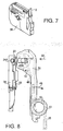
- the cassette holding section 27 is formed to have a substantially rectangular shape viewed from the rear (as shown in Figs. 5 and 6) that is substantially the same as the outside shape of the tape cassette 26, which is shown in Fig. 7.
- portions surrounding the cassette holding section 27 are formed to be protrude portions that protrude toward the back cover side of the tape printing device 1 so that the depth of the cassette holding section 27 with respect to the protruded portions is substantially the same as the thickness of the tape cassette 26.
- a thin plate like thermal head mounting portion 34 On a bottom surface of the cassette holding section 27 at an end portion nearer to the cutting lever 7 (i.e., at a right-hand side end in Fig. 5 or Fig. 6), a thin plate like thermal head mounting portion 34, on which the thermal head 33 is to be mounted, is provided.
- the thermal head mounting portion 34 is formed to extend along the longitudinal direction of the body 2, and stands perpendicularly (i.e., in a direction perpendicular to a plane of Fig. 5 or Fig. 6) from the bottom surface of the cassette holding section 27.
- the thermal head is mounted on the outer side (i.e., the tape cutter side) of the thermal head mounting portion 34.
- a cutout is formed on a right-hand side portion (in Fig. 6) of the protruded potions defining the cassette holding section 27, facing the thermal head 33.
- a platen holder 35 is provided on the rear side of the partition member 30 at the cutout portion such that the platen holder 35 is swingable about a boss 43 (see Fig. 8), to which a through hole 42 formed on a gripping portion side end of the platen holder 35 (see Fig. 8) is fitted.
- the tape printing device 1 is configured such that, when the back cover 3 is detached from the body 2, the platen holder 35 is biased outward by a torsion spring 46 (see Fig.
- a standby position at which the platen holder 35 abuts a position fixing member 37 that is formed at an outward side (tape cutter side) of a substantially rectangular engaging hole 36 formed on the partition member 30, and extends toward the front surface of the tape printing device 1.
- the platen holder 35 is rotatably supported by the boss 43 formed on the partition member 30.
- the circular through hole 42 formed on the platen holder 35 at the lower end in the longitudinal direction thereof is fitted on the boss 43.
- the platen holder 35 is biased outward (in a direction of arrow 46 in Fig. 8) by the torsion spring 45.
- the platen holder 35, at the upper end portion in the longitudinal direction thereof along a plane perpendicular to the longitudinal direction of the tape printing device 1, is formed to have a substantially U-shaped cross section, and through holes 47 are formed on top and bottom surfaces of the upper end portion of the platen holder 35.
- Each of the through holes 47 has a substantially rectangular shape, when viewed from the rear of the body 2.
- Each through hole 47 is long in a direction substantially orthogonal to the longitudinal direction of the platen holder 35 (i.e., in the right-and-left hand direction in Fig. 8).
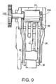
- Rotation shafts 23A of the platen roller 23 are rotatably inserted into the through holes 47 on both sides of the U-shaped portion of the platen holder 35.
- One of the rotation shafts 23A (the one on the left hand side in Fig. 9) extends toward the back side of the partition member 30 (i.e., toward the front side of the body 2), and a platen gear 23B is provided on an end thereof.
- the rotation shafts 23A are biased inward (in a direction indicated by arrow 50 in Fig. 8) by a pressing spring 49.
- the pressing spring 49 is supported at an outer side of a lower end portion of the platen holder 35 in the longitudinal direction thereof and has a substantially U-like shape which is long in the longitudinal direction of the platen holder 35.
- An abutting protrusion 34A is formed on the back cover side surface of the thermal head mounting portion 34 at a location corresponding to a portion to which the platen roller 23 is urged.
- the abutting protrusion 34A has a substantially circular shape viewed from the rear of the body 2, and protrudes toward the back cover side by a predetermined length. It should be noted that the shape of the abutting protrusion 34A viewed from the rear of the body 2 need not be limited to the circular shape. As an alternatively, a semicircular shape having the planar surface facing on the platen roller 23 side may be employed.
- the cutting lever 7 is biased by a not shown spring so that the cutting lever 7 swings outward.
- a cutter 10 is slidably supported by a not shown cutter supporting mechanism which also supports the cutting lever 7 slidably. When the cutting lever 7 is pressed inward, the supporting mechanism moves the cutter 10 toward the tape cassette 26 and cuts the thermal tape 9 located thereat.
- a first gap 39 large enough for inserting a finger is formed at a middle of an upper end side, in the longitudinal direction of the body 2, of the cassette holding section 27.
- the battery holding section 29 is formed on a portion of the partition member 30, which is located in the gripping portion 11, at a side opposite to the thermal head 33 with respect to a longitudinal center line 1X (see Fig. 5), i.e., below the driving motor 25 in the longitudinal direction of the body 2.
- the battery holding section 29 has an elongated rectangular shape when observed from the rear of the body 2 and accommodates four batteries 28 (which are size AA batteries in the present embodiment) with each two batteries 28 arranged and connected along the longitudinal direction of the body 2.
- the battery holding section 29 is formed such that it steps down, from the bottom of the cassette holding section 27, toward the front surface side (left-hand-side in Fig. 4) by a depth that is slightly larger than the diameter of the batteries 28.
- the battery holding section 29 extends in the longitudinal direction of the body 2 such that the upper end of the battery holding section 29 is located in the cassette holding section 27 by a predetermined length.
- a portion of the batteries 28 is located on the front surface side with respect to the tape cassette 26 when the batteries 28 and the tape cassette 26 are attached to the body 2.
- a portion of the cassette holding section 27 facing the battery holding section 29 is cut out to form a second gap 40 that allows a finger to be inserted above the batteries 28 held in the battery holding section 29 when the tape cassette 26 is detached from the tape holding section 29.
- a recess 29a is formed on a thermal head side (the left-hand side in Fig. 6) of the battery holding section 29 defined in the gripping portion 11.
- the recess 29a has a semicircular shape when observed from the rear side of the body 2, and a finger can be inserted thereinto.
- the bottom of the recess 29A is substantially at the same level of the bottom of the battery holding section 29.
- the platen holder 35 When the back cover 3 is removed as shown in Figs. 5 and 6, the platen holder 35 is located at the standby position and the tape cassette 26 can be taken out of the cassette holding section 27 by inserting fingers through the first gap 39 and the second gap 40.
- each battery 28 can be removed by inserting the finger through the recess 29A, and thus the batteries 28 can be exchanged.
- the tape cassette 26 is placed back in the tape holding section 27 and the back cover 3 is attached on the body 2.
- the platen holder 35 swings and is located at the operating position, thereby the tape printing device 1 being operable (see Figs. 11A and 11B).
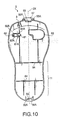
- the back cover 3 will be described with reference to Fig. 10.
- the back cover 3 is provided with resilient engaging pieces 55 and 56 at middle positions, in the width direction, of upper and lower end portions, in the longitudinal direction, of the back cover 3.
- the engaging pieces 55 and 56 are formed to extend toward the body side (i.e., in a direction perpendicular to and upward from a plane of Fig. 9).
- engaging protrusions 55A and 56A are formed at both sides, in a width direction, of a top of each of the resilient engaging pieces 55 and 56.
- the engaging protrusions 55A and 56A engage resiliently with upper and lower end portions of the partition member 30 in the longitudinal direction thereof.
- the back cover 3 is resiliently secured to the back side of the body 2.
- a pressing portion 57 protrudes outward from a base of the resilient engaging piece 55 at the upper side in the longitudinal direction. By pressing the pressing portion 57 inward (i.e., in the downward direction in Fig. 10), each engaging protrusion 55A of the resilient engaging piece 55 is detached from the partition member 30, and the back cover 3 can be removed easily from the back side portion of the body 2.
- a tape discharging opening 8 is formed beside the resilient engaging piece 55 at the upper side of the back cover 3 in the longitudinal direction thereof (see Figs. 10 and 3).
- a regulating piece 61 having a semi-circular horizontal section and a protrusion portion 62 having a substantially w shape horizontal section are formed below, in the longitudinal direction, the tape discharging opening 8.
- the regulating piece 61 is formed to protrude substantially perpendicularly from the inner surface of the back cover 3 at a position corresponding to the abutting protrusion 34A formed at the top end of the thermal head mounting portion 34.
- the regulating piece 61 substantially engages with the abutting protrusion 34A so as to restrict the deformation of the thermal head mounting member as will be described later.
- the protrusion portion 62 is formed to protrude substantially perpendicularly on the inner surface of the back cover 3 at a position corresponding to the engaging hole 36 of the partition member 30. Further, as shown in Fig. 11B, the height of the regulating piece 61 from the inner surface of the back cover 3 is adjusted such that the regulating piece 61 faces the outer surface of the abutting protrusion 34A in the width direction thereof when the back cover 3 is attached to the back side of the body 2. Further, as shown in Fig.
- the height of the protrusion portion 62 from the inner wall of the back cover 3 is adjusted such that the protrusion portion 62 is inserted through the engaging hole 36 and interposed between the side portion of the platen holder 35 and the position fixing member 37 when the back cover 3 is attached to the body 2.
- First ribs 61A extending outward in the width direction from both side portions of the regulating piece 61, and second ribs 62A extending inward in the width direction from both side portions of the protrusion portion 62 are joined at a substantially middle portion between the regulating piece 61 and the protrusion portion 62 to form a rib portion having a substantially rectangular cross sectional shape.
- the firs ribs 61A and the second ribs 62A have a substantially constant height.
- the tip of the protrusion portion 62 is inclined such that the height on the outer side is greater than the height on the inner side as shown in Fig. 11B. Therefore, the protrusion portion 62 can easily be interposed between the platen holder 35 and the position fixing member 37.
- a cassette holding rib 63 is formed on an opposite side of the regulating piece 61 with respect to the longitudinal center line 3X.
- the cassette holding rib 63 has a height that substantially reaches the top surface (i.e., the surface facing the inner wall of the back cover 3) of the tape cassette 26 when the back cover 3 is attached to the body 2.
- the back cover 3 is provided with a pair of battery holding ribs 64, which are formed on the inner wall at the gripping portion 11 at an upper portion of the gripping portion 11 and at a substantially middle portion of the gripping portion 11, in the longitudinal direction of the back cover 3.
- the pair of battery holding ribs 64 are formed to extend in a direction substantially perpendicular to the longitudinal direction of the back cover 3 over the entire width of the back cover 3.
- Each battery holding rib 64 is formed to protrude substantially perpendicularly to the inner wall of the back cover 3 at a height that reaches the top surface (i.e. , the back cover side surface) of the partition member 30 to hold the batteries 28 in place when the back cover 3 is attached to the body 2.
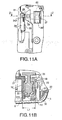
- Fig. 11A an enlarged partial plan view showing a portion around the thermal head 33
- Fig. 11B is a cross sectional view taken along line Z-Z in Fig. 11A.
- the protrusion portion 62 provided on the inner surface of the back cover 3 is inserted through the engaging hole 36 and interposed between the side portion of the platen holder 35 and the position fixing member 37 (the protrusion portion 62 being shown as a cross section by dotted lines).
- the platen holder 35 swings toward the thermal head 33, while due to the urging force of the torsion spring, the platen holder 35 is held at a position where the side portion of the platen holder 35 abuts the inner side of the protrusion portion 62 (i.e., the operating position).
- the platen roller 23 is urged toward the thermal head 33, thus, the platen roller 23 moves outward (i.e., toward the right-hand-side in Fig. 11A) along the through holes 47 with bending the pressing spring 49 since the platen roller 23 is pressed against the thermal head 33.
- the platen roller 23 can press the thermal tape 9 located between the platen roller 23 and the thermal head 33 against the thermal head 33 by a pressing force corresponding to bending amount of the pressing spring 49.
- the regulating piece 61 provided on the inner surface of the back cover 3 is arranged at a position where it faces the abutting protrusion 34A, which protrudes from the upper end portion of the thermal head mounting portion 34, at the side thereof opposite from the platen holder 35.
- a gap of about 0.1-0.3 mm is formed between the regulating piece 61 and the abutting portion 34, taking a manufacturing error in account.
- the platen gear 23B provided on the back side end portion of the platen roller 23 engages with the not shown gear mechanism, which is rotatably driven by the driving motor 25, to drive the platen roller 23 to rotate and feed the thermal tape 9 printed by the thermal head 33.
- the thermal tape 9 accommodated in the tape cassette 26 is configured such that color is developed when heat is applied by the thermal head 33.
- the thermal energy required for each heater element of the thermal head 33 can be kept lower than that in printing on a tape by a thermal ink ribbon, and the heating temperature of the thermal head can be suppressed at a lower level. Therefore, the creep deformation of the thermal head mounting portion 34 due to the heat generated by the thermal head 33 can be suppressed.
- the thermal tape 9 may be one having an adhesive previously applied on the back side thereof and a release tape tentatively adhered on the adhesive layer.
- the operator holds the gripping portion 11 of the tape printing device 1 with his/her left hand with the LCD 6 displaying the printing data.
- the operator creates desired printing data with ease by pressing the character input keys 12, the space key 13, the case shift key 14, the cursor key 16, and the return key 18 using the thumb of the left hand.
- the print key 15 is pressed with the left hand thumb
- the thermal tape is printed.
- the cutting lever 7 is pressed inward by the thumb of the left hand, which currently holds the tape printing device 1, to cut the thermal tape 9, on which the desired printing data is printed and is discharged from the tape discharging opening 8.
- the operator can obtain a tape on which arbitrary data is printed by using only the left hand which is holding the gripping portion 11 of the tape printing device 1.
- the platen holder 35 moves to the operating position and the thermal head 33 is pressed by the platen roller 23 with the tape located therebetween.
- the thermal head mounting portion 34 which is a thin plate like member on the side of which the thermal head 33 is mounted, is applied with a force to bend the same toward the direction pressed by the platen roller 23, the thermal head mounting portion 34 is supported on both sides thereof in the bending direction since the abutting protrusion 34A provided on the outer end portion of the thermal head mounting portion 34 abuts the regulating piece 61 formed on the inner surface of the back cover 3 in a vicinity of the surface of the abutting protrusion 34A on the side thereof opposite from the platen holder 35.
- the thermal head mounting portion 34 is supported at both sides in the direction where the bending force is applied due to the pressing force of the platen roller 23 when the back cover 3 is attached to the body 2, the creep deformation of the thermal head mounting portion 34 can be prevented effectively even in the case it is stored or used for a long time in high temperatures environment, and hence deterioration of the printing quality can be prevented for a long time.
- the abutting protrusion 34A is formed on the end portion of the thermal head mounting portion 34 so that it faces the rotation shaft 23A of the platen roller 23 when the platen holder 35 is located at the operating position. Since the abutting protrusion 34A and the platen roller 23 face to each other when the back cover 3 is attached to the body 2, the thermal head mounting portion 34 is reliably supported at both sides to which the pressing force of the platen roller 23 works. With this structure, the bending deformation of the thermal head mounting portion 34 due to the pressing force of the platen roller 23 can be prevented more reliably, and the abutting protrusion 34A can be made compact, and hence the-device body can be made compact with ease.
- the abutting protrusion 34A having a substantially circular horizontal section abuts the regulating piece 61 having a substantially semicircular horizontal section into which the abutting portion can be inserted.
- the abutting protrusion 34A is supported inside the regulating piece 61 in the thermal head's pressing direction irrespective of the direction thereof. Therefore, the thermal head mounting portion 34 can be reliably supported at both sides thereof in the bending direction thereof.
- the protrusion portion 62 provided on the inner surface of the back cover 3 presses the outer side of the platen holder 35 to move the platen holder 35 from the standby position to the operating position against the force of the torsion spring 45 that biases the platen holder 35 to swing from the operating position to the standby position. Therefore, the platen holder 35 can be automatically moved to the operating position with a simple structure, and the tape printing device 1 can be made compact and the manufacturing cost thereof can be reduced.
- the cassette holding section 27 and the thermal head mounting portion 34 are made of synthetic resin, they can be simultaneously made by means of resin molding which enables a large amount of reduction of the manufacturing cost. Further, since bending deformation of the resin thermal head mounting portion 34 due to the pressure applied by the platen roller 23 can be minimized with use of the regulating piece 61 of the back cover 3, the deformation of the resin thermal head mounting portion 34 due to high temperature creep is prevented. Thus, the tape printing quality can be kept uniform and deterioration of the printing quality of the thermal tape 9 can be prevented for a long time.
- the back cover 3 is made of synthetic resin, it can be made by resin molding which enables a large reduction of the manufacturing cost. Further, the mechanical strength of the resin regulating piece 61 and the resin protrusion portion 62 is enhanced by the first ribs 61A and the second ribs 62A. Therefore, deformations of the resin regulating piece 61 and the resin protrusion portion 62 due to high temperature creep or the like are prevented. Thus, printing quality of the thermal tape 9 can be kept uniform and deterioration of the printing quality of the thermal tape 9 can be prevented for a long time.
- the regulating piece 61 and the protrusion portion 62A are joined between the regulating piece 61 and the protrusion portion 62 to form the rib portion having a substantially rectangular cross section, the regulating piece 61 and the protrusion portion 62 can be easily formed by resin molding with a distance L1 therebetween of high accuracy.
- the pressing force of the platen roller 23 can be kept at a constant load, and hence the printing quality of the thermal tape 9 can be kept more uniform and deterioration of printing quality of the thermal tape 9 can be reliably prevented for a long time.
- the present invention is not limited to the embodiment described above and various changes and modifications may be made without departing from the scope of the invention.
- the abutting protrusion 34A is formed to have a substantially circular horizontal cross section in the embodiment described above, it may be formed to have a substantially semicircular horizontal section with a convex surface being located on the opposite side of the platen holder 35. Even with this alternative, the abutting protrusion 34A abuts the inner surface of the regulating piece 61.
- the abutting protrusion 34A can be supported efficiently and the mechanical strength of the abutting protrusion 34A can be improved by enlarging the section thereof.
- the cassette holding section 27, the thermal head mounting portion 34 and the battery holding section 29 are formed on the partition member 30.
- the partition member 30 may be divided into two in the longitudinal direction thereof at the upper end of the gripping portion 11 in the longitudinal direction thereof, and the cassette holding section 27 and the thermal head mounting portion 34 may be made of heat resistance resin.
- the abutting protrusion 34A is provided on the thermal head mounting portion 34 at the end portion thereof at a location corresponding to the platen roller 23.
- a plurality of abutting protrusions 34A may be provided on the thermal head mounting portion 34 on the end portion at a back cover side thereof along the longitudinal direction, and the corresponding number of regulating piece 61 may be provided on the inner surface of the back cover 3 at positions corresponding to the abutting protrusions 34A.
- the abutting portion provided on the cover side end portion of the thermal head mounting portion abuts the regulating member provided on the inner surface of the back cover such that it faces the surface of the abutting portion opposite from the platen mechanism.
- the bending deformation of the thermal head mounting portion due to the pressing force of the platen mechanism can be prevented. Accordingly, such a tape printing device can print on a tape with uniform quality.
- the thermal head mounting portion is supported at both sides (i.e., at the front side and the rear side) against the pressing force of the thermal head mounting portion, the creep deformation of the thermal head mounting portion can be prevented even when the tape printing devices is stored or used for a long time in high temperature environment.
- a tape printing device capable of preventing the deterioration of the tape printing quality for a long time.
- the thermal head mounting portion 34 which is a relatively thin plate-like member formed on the bottom of the cassette holding section, is pressed by the platen roller through the thermal head mounted on the side of the thermal head mounting portion.
- the thermal head mounting portion is pressed to be bent in the direction by the platen roller.
- the abutting protrusion provided on the cover side end portion of the thermal head mounting member abuts the regulating member formed on the inner surface of the back cover, the thermal head mounting portion is supported at both sides thereof.
- the thermal head mounting portion is supported at both sides (i.e., at the cassette holding section side and at the back cover side) when the back cover is attached to the device body, the creep deformation of the thermal head mounting portion can be prevented even if the tape printing device is stored or used for a long time in high temperatures environment, and hence deterioration of the printing quality can be prevented for a long time.
- the platen mechanism moves from a standby position to a operating position in association with a movement of the back cover member covering the cassette holding section.
- the platen mechanism moves to the operating position and is biased toward the thermal head, accordingly the tape can be automatically pressed against the thermal head when the tape cassette is accommodated in the cassette holding section and the cover is attached to the body.
- the platen mechanism moves to the standby position when the cover is removed, the tape cassette can be removed from the tape cassette holding section without causing damage to the tape.
- the abutting portion is formed on the back cover side end portion of the thermal head mounting member so that it faces a rotation axis of the platen roller when the platen mechanism is located at the operating position, the platen roller, which is biased toward the thermal head by the biasing mechanism, faces this abutting member.
- both sides of the thermal head mounting portion, which is pressed by the platen roller are reliably supported.
- the abutting portion formed to have a circular horizontal section or a substantially circular horizontal section abuts the regulating member having a substantially semicircular horizontal section into which the abutting portion can be inserted.
- the abutting portion is supported inside the regulating member in the thermal head's pressing direction irrespective of the direction thereof. Therefore, the thermal head mounting portion can be reliably supported at both sides thereof in the bending direction thereof.
- the mechanical strength of the regulating member is enhanced by the pair of the first ribs extending from both sides of the regulating member, the bending deformation due to a counter force of the regulating member for supporting the abutting portion can be prevented to achieve uniform quality printing on the tape.
- the mechanical strength of the regulating member in the direction of the counter force for supporting the abutting portion is improved by the pair of the first ribs, the creep deformation of the regulating member caused by storing or using it for a long time in high temperatures environment can be prevented, and hence deterioration of the tape printing quality can be reliably prevented for a long time.
- the protrusion portion provided on the inner surface of the cover member presses the outer side of the platen mechanism to move the platen mechanism from the standby position to the operating position against the swinging means that swings the platen mechanism from the operating position to the standby position. Therefore, the platen mechanism can be moved to the operating position by a simple arrangement, and the tape printing device can be made compact and the size and the manufacturing cost of the device body can be reduced.
- the mechanical strength of the protrusion portion is improved by the pair of the second ribs extending from both sides of the protrusion portion, the bending deformation due to the counter force of the protrusion for pressing the platen mechanism can be prevented to achieve uniform tape printing quality.
- the mechanical strength of the protrusion portion in the direction of the counter force pressing the platen mechanism is improved by the pair of the second ribs when the cover is attached to the device body, the creep deformation of the protrusion portion caused by storing or using it for a long time in high temperatures environment can be prevented, and hence deterioration of the tape printing quality can be reliably prevented for a long time.
- the tape printing device described above since the first ribs and the second ribs are joined between the regulating member and the protrusion portion to form a rib portion having a substantially rectangular horizontal section, the mechanical strength of the regulating member and the protrusion portion can be further improved, and the first ribs and the second ribs can be downsized, and hence the device body can be downsized with ease.
- the cassette holding section and the thermal head mounting portion are made of resin, they can be formed simultaneously by resin molding and a deep cut of the manufacturing cost can be achieved. Further, the bending deformation of the resin thermal head mounting portion caused by the pressing force of the platen mechanism can be reduced to a minimum by the regulating member of the cover. Therefore, the deformation of the resin thermal head mounting portion due to high temperature creep or the like is prevented and the tape printing quality can be kept uniform and deterioration of the tape printing quality can be prevented for a long time.
- the cover is made of resin, it can be made of resin molding, and hence a deep cut of the manufacturing cost there of can be achieved. Further, the mechanical strength of the resin regulating member and the resin protrusion portion provided on the inner surface of the cover is improved by the first ribs and the second ribs. Therefore, deformations of the resin regulating member and the resin protrusion portion due to high temperature creep or the like are prevented. Thus, tape printing quality can be kept uniform and deterioration of the tape printing quality can be prevented for a long time.
- the regulating member and the protrusion portion can be easily formed by resin molding with a distance therebetween of high accuracy.
- the pressing force of the platen mechanism can be kept at a constant load, and hence the tape printing quality can be kept further uniform and deterioration of tape printing quality can be reliably prevented for a long time.
Landscapes
- Printers Characterized By Their Purpose (AREA)
- Impression-Transfer Materials And Handling Thereof (AREA)
- Electronic Switches (AREA)
- Printers Or Recording Devices Using Electromagnetic And Radiation Means (AREA)
- Handling Of Sheets (AREA)
Abstract
Description
Claims (17)
- A tape printing device that prints letters/characters on a tape-form thermal recording medium, comprising:wherein said thermal head mounting portion has an abutting member,a device body, a cassette holding section being formed in said device body to accommodate a tape cassette containing the tape-form recording medium;a cover member that covers said cassette holding section;a thermal head that applies heat to print letters/characters on the tape-form recording medium;a thermal head mounting portion formed on a bottom of said cassette holding section, said thermal head mounting portion including a plate-like member that protrudes from the bottom of said cassette holding section toward said cover member, said thermal head being attached to a side of said plate-like member; anda platen mechanism having a platen which faces said thermal head and is biased toward said thermal head,
wherein said cover member has a regulating member,
said abutting member and said regulating member being configured such that said abutting member abuts said regulating member from a direction opposite to a direction in which said platen is biased toward said thermal head at least when said cover member covers said cassette holding section, deformation of said plate-like member urged by said platen being prevented as a displacement of said abutting member is prevented by said regulating member. - The tape printing device according to claim 1, wherein said abutting member includes a protruded member protruding from a side end surface of said plate-like member.
- The tape printing device according to claim 1 or 2, wherein said regulating member is formed on an inner surface, which faces said thermal head mounting portion, of said cover member.
- The tape printing device according to claim 1, 2 or 3, wherein said protruded member has a substantially circular cross section along a plane perpendicular to a protruding direction of said protruded member or
said protruded member has a substantially semicircular cross section along a plane perpendicular to a protruding direction of said protruded member, a convex surface of said protruded member facing said regulating member. - The tape printing device according to one of claims 2 to 4, wherein said regulating member has a receiving portion that receives said protruded member, at least a portion of said receiving portion abutting said protruded member having a concave shape fitting to the shape of said protruded member.
- The tape printing device according to any one of claims 1 through 5,
wherein said platen mechanism is configured such that said platen moves between an operating position at which said platen is biased toward said thermal head and a standby position at which said platen is retracted from said operating position; and
wherein said abutting member faces said regulating member only when said platen is located at said operating position. - The tape printing device according to any one of claims 1 through 6,
wherein said cover member is detachably attached to said body, and
wherein said platen mechanism is configured such that said platen moves between an operating position at which said platen is biased toward said thermal head and a standby position at which said platen is retracted from said operating position in association with attachment/detachment of said cover member with respect to said body. - The tape printing device according to claim 6 or 7,
wherein said platen mechanism includes a platen roller, and a biasing mechanism that biases said platen roller toward said thermal head, and
wherein said abutting portion is formed on the cover member side end portion of said thermal head mounting portion such that it faces a rotation axis of said platen roller when said platen mechanism is at the operating position. - The tape printing device according to claim 6 or 7,
wherein said platen mechanism has a swinging mechanism that swings said platen mechanism from the operating position to the standby position about a fixed point,
wherein said cover member has a protrusion portion formed on said inner surface, and
wherein said protrusion portion presses an outer side of said platen mechanism to move said platen mechanism from the standby position to the operating position against said swinging means. - The tape printing device according to any one of claims 1 through 7,
wherein said platen mechanism has a moving mechanism that moves said platen between the operating position and the standby position,
wherein said cover member has a protrusion portion formed on the inner surface of said cover member, said protrusion portion affecting said moving mechanism to move said platen. - The tape printing device according to claim 10,
wherein said abutting member includes a protruded member protruding from a side end surface of said plate-like member, and
wherein said regulating member is formed on the inner surface, which faces said thermal head mounting portion, of said cover member. - The tape printing device according to claim 11, wherein said cover member has a pair of first ribs, said first ribs being formed on said inner surface of said cover member and extending from both sides of said regulating member.
- The tape printing device according to claim 11 or 12, wherein said cover member has a pair of second ribs, said second ribs being formed on said inner surface of said cover member and extending from both sides of said protrusion portion.
- The tape printing device according to claim 13, wherein said first ribs and said second ribs are joined between said regulating member and said protrusion portion.
- The tape printing device according to any one of claims 10 to 14, wherein a distance between said regulating member and said protrusion portion is determined such that said platen is urged against said thermal head at a predetermined force.
- The tape printing device according to any one of claims 10 through 15, wherein said regulating member and said protrusion portion are formed integrally with said cover member.
- The tape printing device according to any one of the preceding claims, wherein said thermal head mounting member and said cassette holding section are formed of resin and/or
said cover member is made of resin and/or
said thermal head mounting member is formed integrally with said cassette holding section.
Applications Claiming Priority (2)
| Application Number | Priority Date | Filing Date | Title |
|---|---|---|---|
| JP2002369504A JP3823918B2 (en) | 2002-12-20 | 2002-12-20 | Tape printer |
| JP2002369504 | 2002-12-20 |
Publications (2)
| Publication Number | Publication Date |
|---|---|
| EP1431047A1 true EP1431047A1 (en) | 2004-06-23 |
| EP1431047B1 EP1431047B1 (en) | 2005-06-08 |
Family
ID=32376320
Family Applications (1)
| Application Number | Title | Priority Date | Filing Date |
|---|---|---|---|
| EP03029089A Expired - Lifetime EP1431047B1 (en) | 2002-12-20 | 2003-12-17 | Tape printing device |
Country Status (6)
| Country | Link |
|---|---|
| US (1) | US6930697B2 (en) |
| EP (1) | EP1431047B1 (en) |
| JP (1) | JP3823918B2 (en) |
| CN (1) | CN1315654C (en) |
| AT (1) | ATE297317T1 (en) |
| DE (1) | DE60300812T2 (en) |
Families Citing this family (14)
| Publication number | Priority date | Publication date | Assignee | Title |
|---|---|---|---|---|
| JP2008100381A (en) * | 2006-10-17 | 2008-05-01 | Seiko Instruments Inc | Thermal printer |
| JP4665973B2 (en) | 2008-01-31 | 2011-04-06 | ブラザー工業株式会社 | Tape printer |
| USD631826S1 (en) | 2008-10-14 | 2011-02-01 | Boston-Power, Inc. | Battery pack |
| USD631827S1 (en) | 2008-10-14 | 2011-02-01 | Boston-Power, Inc. | Battery pack |
| USD631830S1 (en) | 2008-10-14 | 2011-02-01 | Boston-Power, Inc. | Battery pack |
| USD631829S1 (en) | 2008-10-14 | 2011-02-01 | Boston-Power, Inc. | Battery pack |
| USD631832S1 (en) * | 2008-10-14 | 2011-02-01 | Boston-Power, Inc. | Battery pack |
| USD631831S1 (en) | 2008-10-14 | 2011-02-01 | Boston-Power, Inc. | Battery pack |
| USD631828S1 (en) | 2008-10-14 | 2011-02-01 | Boston-Power, Inc. | Battery pack |
| USD631825S1 (en) | 2008-10-14 | 2011-02-01 | Boston-Power, Inc. | Battery pack |
| USD631833S1 (en) | 2008-10-14 | 2011-02-01 | Boston-Power, Inc. | Battery pack |
| CN102001234B (en) * | 2010-09-09 | 2016-03-16 | 刘元勋 | A portable printer capable of receiving wireless data |
| JP2016175384A (en) * | 2015-03-23 | 2016-10-06 | セイコーエプソン株式会社 | Tape printer |
| JP1546043S (en) * | 2015-09-07 | 2019-03-11 |
Citations (3)
| Publication number | Priority date | Publication date | Assignee | Title |
|---|---|---|---|---|
| US5839840A (en) * | 1996-09-26 | 1998-11-24 | Brother Kogyo Kabushiki Kaisha | Tape printing apparatus |
| EP1120263A2 (en) * | 2000-01-27 | 2001-08-01 | Esselte N.V. | Printing device |
| US6435744B1 (en) * | 1998-04-21 | 2002-08-20 | Esselte N.V. | Tape printing device and tape cassette |
Family Cites Families (3)
| Publication number | Priority date | Publication date | Assignee | Title |
|---|---|---|---|---|
| JPH0825753A (en) | 1994-07-18 | 1996-01-30 | Brother Ind Ltd | Printing part support device in printing tape making device |
| EP0794066B1 (en) * | 1996-03-07 | 2000-05-17 | Esselte N.V. | Means to detect a ribbon cassette in a tape printing apparatus |
| GB2318094A (en) * | 1996-10-14 | 1998-04-15 | Esselte Nv | Tape cassette with tape printing apparatus |
-
2002
- 2002-12-20 JP JP2002369504A patent/JP3823918B2/en not_active Expired - Fee Related
-
2003
- 2003-12-08 US US10/728,776 patent/US6930697B2/en not_active Expired - Lifetime
- 2003-12-17 AT AT03029089T patent/ATE297317T1/en not_active IP Right Cessation
- 2003-12-17 DE DE60300812T patent/DE60300812T2/en not_active Expired - Lifetime
- 2003-12-17 EP EP03029089A patent/EP1431047B1/en not_active Expired - Lifetime
- 2003-12-19 CN CNB2003101239401A patent/CN1315654C/en not_active Expired - Fee Related
Patent Citations (3)
| Publication number | Priority date | Publication date | Assignee | Title |
|---|---|---|---|---|
| US5839840A (en) * | 1996-09-26 | 1998-11-24 | Brother Kogyo Kabushiki Kaisha | Tape printing apparatus |
| US6435744B1 (en) * | 1998-04-21 | 2002-08-20 | Esselte N.V. | Tape printing device and tape cassette |
| EP1120263A2 (en) * | 2000-01-27 | 2001-08-01 | Esselte N.V. | Printing device |
Also Published As
| Publication number | Publication date |
|---|---|
| DE60300812T2 (en) | 2006-05-18 |
| CN1315654C (en) | 2007-05-16 |
| JP2004195894A (en) | 2004-07-15 |
| JP3823918B2 (en) | 2006-09-20 |
| HK1064336A1 (en) | 2005-01-28 |
| DE60300812D1 (en) | 2005-07-14 |
| US20040155951A1 (en) | 2004-08-12 |
| EP1431047B1 (en) | 2005-06-08 |
| US6930697B2 (en) | 2005-08-16 |
| CN1509886A (en) | 2004-07-07 |
| ATE297317T1 (en) | 2005-06-15 |
Similar Documents
| Publication | Publication Date | Title |
|---|---|---|
| EP1431047B1 (en) | Tape printing device | |
| US6503005B1 (en) | Hand-held tape printing device | |
| US6602009B2 (en) | Tape cutting mechanism for tape printing apparatus | |
| US6332725B1 (en) | Tape printing apparatus and tape holding cases | |
| EP2903832B1 (en) | Printing apparatus | |
| US7021845B2 (en) | Tape printing device | |
| US5758980A (en) | Tape printer providing improved layout of drive motor and battery portion | |
| US7077587B2 (en) | Tape printing apparatus with tape cassette guide members | |
| EP2314457B1 (en) | Printing apparatus | |
| JP4100436B2 (en) | Tape printer | |
| JP4438429B2 (en) | switch | |
| JP4049066B2 (en) | Tape printer | |
| HK1064336B (en) | Tape printing device | |
| JP3867679B2 (en) | Tape printer | |
| JPH1067150A (en) | Printing device |
Legal Events
| Date | Code | Title | Description |
|---|---|---|---|
| PUAI | Public reference made under article 153(3) epc to a published international application that has entered the european phase |
Free format text: ORIGINAL CODE: 0009012 |
|
| AK | Designated contracting states |
Kind code of ref document: A1 Designated state(s): AT BE BG CH CY CZ DE DK EE ES FI FR GB GR HU IE IT LI LU MC NL PT RO SE SI SK TR |
|
| AX | Request for extension of the european patent |
Extension state: AL LT LV MK |
|
| 17P | Request for examination filed |
Effective date: 20040812 |
|
| GRAP | Despatch of communication of intention to grant a patent |
Free format text: ORIGINAL CODE: EPIDOSNIGR1 |
|
| AKX | Designation fees paid |
Designated state(s): AT BE BG CH CY CZ DE DK EE ES FI FR GB GR HU IE IT LI LU MC NL PT RO SE SI SK TR |
|
| GRAS | Grant fee paid |
Free format text: ORIGINAL CODE: EPIDOSNIGR3 |
|
| GRAA | (expected) grant |
Free format text: ORIGINAL CODE: 0009210 |
|
| AK | Designated contracting states |
Kind code of ref document: B1 Designated state(s): AT BE BG CH CY CZ DE DK EE ES FI FR GB GR HU IE IT LI LU MC NL PT RO SE SI SK TR |
|
| PG25 | Lapsed in a contracting state [announced via postgrant information from national office to epo] |
Ref country code: IT Free format text: LAPSE BECAUSE OF FAILURE TO SUBMIT A TRANSLATION OF THE DESCRIPTION OR TO PAY THE FEE WITHIN THE PRESCRIBED TIME-LIMIT;WARNING: LAPSES OF ITALIAN PATENTS WITH EFFECTIVE DATE BEFORE 2007 MAY HAVE OCCURRED AT ANY TIME BEFORE 2007. THE CORRECT EFFECTIVE DATE MAY BE DIFFERENT FROM THE ONE RECORDED. Effective date: 20050608 Ref country code: EE Free format text: LAPSE BECAUSE OF FAILURE TO SUBMIT A TRANSLATION OF THE DESCRIPTION OR TO PAY THE FEE WITHIN THE PRESCRIBED TIME-LIMIT Effective date: 20050608 Ref country code: SI Free format text: LAPSE BECAUSE OF FAILURE TO SUBMIT A TRANSLATION OF THE DESCRIPTION OR TO PAY THE FEE WITHIN THE PRESCRIBED TIME-LIMIT Effective date: 20050608 Ref country code: CZ Free format text: LAPSE BECAUSE OF FAILURE TO SUBMIT A TRANSLATION OF THE DESCRIPTION OR TO PAY THE FEE WITHIN THE PRESCRIBED TIME-LIMIT Effective date: 20050608 Ref country code: LI Free format text: LAPSE BECAUSE OF FAILURE TO SUBMIT A TRANSLATION OF THE DESCRIPTION OR TO PAY THE FEE WITHIN THE PRESCRIBED TIME-LIMIT Effective date: 20050608 Ref country code: SK Free format text: LAPSE BECAUSE OF FAILURE TO SUBMIT A TRANSLATION OF THE DESCRIPTION OR TO PAY THE FEE WITHIN THE PRESCRIBED TIME-LIMIT Effective date: 20050608 Ref country code: FI Free format text: LAPSE BECAUSE OF FAILURE TO SUBMIT A TRANSLATION OF THE DESCRIPTION OR TO PAY THE FEE WITHIN THE PRESCRIBED TIME-LIMIT Effective date: 20050608 Ref country code: AT Free format text: LAPSE BECAUSE OF FAILURE TO SUBMIT A TRANSLATION OF THE DESCRIPTION OR TO PAY THE FEE WITHIN THE PRESCRIBED TIME-LIMIT Effective date: 20050608 Ref country code: NL Free format text: LAPSE BECAUSE OF FAILURE TO SUBMIT A TRANSLATION OF THE DESCRIPTION OR TO PAY THE FEE WITHIN THE PRESCRIBED TIME-LIMIT Effective date: 20050608 Ref country code: TR Free format text: LAPSE BECAUSE OF FAILURE TO SUBMIT A TRANSLATION OF THE DESCRIPTION OR TO PAY THE FEE WITHIN THE PRESCRIBED TIME-LIMIT Effective date: 20050608 Ref country code: CH Free format text: LAPSE BECAUSE OF FAILURE TO SUBMIT A TRANSLATION OF THE DESCRIPTION OR TO PAY THE FEE WITHIN THE PRESCRIBED TIME-LIMIT Effective date: 20050608 Ref country code: RO Free format text: LAPSE BECAUSE OF FAILURE TO SUBMIT A TRANSLATION OF THE DESCRIPTION OR TO PAY THE FEE WITHIN THE PRESCRIBED TIME-LIMIT Effective date: 20050608 |
|
| REG | Reference to a national code |
Ref country code: GB Ref legal event code: FG4D |
|
| REG | Reference to a national code |
Ref country code: CH Ref legal event code: EP |
|
| REF | Corresponds to: |
Ref document number: 60300812 Country of ref document: DE Date of ref document: 20050714 Kind code of ref document: P |
|
| REG | Reference to a national code |
Ref country code: IE Ref legal event code: FG4D |
|
| PG25 | Lapsed in a contracting state [announced via postgrant information from national office to epo] |
Ref country code: DK Free format text: LAPSE BECAUSE OF FAILURE TO SUBMIT A TRANSLATION OF THE DESCRIPTION OR TO PAY THE FEE WITHIN THE PRESCRIBED TIME-LIMIT Effective date: 20050908 Ref country code: GR Free format text: LAPSE BECAUSE OF FAILURE TO SUBMIT A TRANSLATION OF THE DESCRIPTION OR TO PAY THE FEE WITHIN THE PRESCRIBED TIME-LIMIT Effective date: 20050908 Ref country code: SE Free format text: LAPSE BECAUSE OF FAILURE TO SUBMIT A TRANSLATION OF THE DESCRIPTION OR TO PAY THE FEE WITHIN THE PRESCRIBED TIME-LIMIT Effective date: 20050908 Ref country code: BG Free format text: LAPSE BECAUSE OF FAILURE TO SUBMIT A TRANSLATION OF THE DESCRIPTION OR TO PAY THE FEE WITHIN THE PRESCRIBED TIME-LIMIT Effective date: 20050908 |
|
| PG25 | Lapsed in a contracting state [announced via postgrant information from national office to epo] |
Ref country code: ES Free format text: LAPSE BECAUSE OF FAILURE TO SUBMIT A TRANSLATION OF THE DESCRIPTION OR TO PAY THE FEE WITHIN THE PRESCRIBED TIME-LIMIT Effective date: 20050919 |
|
| PG25 | Lapsed in a contracting state [announced via postgrant information from national office to epo] |
Ref country code: PT Free format text: LAPSE BECAUSE OF FAILURE TO SUBMIT A TRANSLATION OF THE DESCRIPTION OR TO PAY THE FEE WITHIN THE PRESCRIBED TIME-LIMIT Effective date: 20051114 |
|
| NLV1 | Nl: lapsed or annulled due to failure to fulfill the requirements of art. 29p and 29m of the patents act | ||
| PG25 | Lapsed in a contracting state [announced via postgrant information from national office to epo] |
Ref country code: HU Free format text: LAPSE BECAUSE OF FAILURE TO SUBMIT A TRANSLATION OF THE DESCRIPTION OR TO PAY THE FEE WITHIN THE PRESCRIBED TIME-LIMIT Effective date: 20051209 |
|
| REG | Reference to a national code |
Ref country code: CH Ref legal event code: PL |
|
| PG25 | Lapsed in a contracting state [announced via postgrant information from national office to epo] |
Ref country code: CY Free format text: LAPSE BECAUSE OF FAILURE TO SUBMIT A TRANSLATION OF THE DESCRIPTION OR TO PAY THE FEE WITHIN THE PRESCRIBED TIME-LIMIT Effective date: 20051217 |
|
| PG25 | Lapsed in a contracting state [announced via postgrant information from national office to epo] |
Ref country code: IE Free format text: LAPSE BECAUSE OF NON-PAYMENT OF DUE FEES Effective date: 20051219 |
|
| PG25 | Lapsed in a contracting state [announced via postgrant information from national office to epo] |
Ref country code: LU Free format text: LAPSE BECAUSE OF NON-PAYMENT OF DUE FEES Effective date: 20051231 Ref country code: MC Free format text: LAPSE BECAUSE OF NON-PAYMENT OF DUE FEES Effective date: 20051231 |
|
| ET | Fr: translation filed | ||
| PLBE | No opposition filed within time limit |
Free format text: ORIGINAL CODE: 0009261 |
|
| STAA | Information on the status of an ep patent application or granted ep patent |
Free format text: STATUS: NO OPPOSITION FILED WITHIN TIME LIMIT |
|
| 26N | No opposition filed |
Effective date: 20060309 |
|
| REG | Reference to a national code |
Ref country code: IE Ref legal event code: MM4A |
|
| REG | Reference to a national code |
Ref country code: FR Ref legal event code: PLFP Year of fee payment: 13 |
|
| REG | Reference to a national code |
Ref country code: FR Ref legal event code: PLFP Year of fee payment: 14 |
|
| REG | Reference to a national code |
Ref country code: FR Ref legal event code: PLFP Year of fee payment: 15 |
|
| PGFP | Annual fee paid to national office [announced via postgrant information from national office to epo] |
Ref country code: GB Payment date: 20211130 Year of fee payment: 19 Ref country code: FR Payment date: 20211117 Year of fee payment: 19 Ref country code: DE Payment date: 20211110 Year of fee payment: 19 |
|
| PGFP | Annual fee paid to national office [announced via postgrant information from national office to epo] |
Ref country code: BE Payment date: 20211117 Year of fee payment: 19 |
|
| REG | Reference to a national code |
Ref country code: DE Ref legal event code: R119 Ref document number: 60300812 Country of ref document: DE |
|
| GBPC | Gb: european patent ceased through non-payment of renewal fee |
Effective date: 20221217 |
|
| REG | Reference to a national code |
Ref country code: BE Ref legal event code: MM Effective date: 20221231 |
|
| PG25 | Lapsed in a contracting state [announced via postgrant information from national office to epo] |
Ref country code: GB Free format text: LAPSE BECAUSE OF NON-PAYMENT OF DUE FEES Effective date: 20221217 Ref country code: DE Free format text: LAPSE BECAUSE OF NON-PAYMENT OF DUE FEES Effective date: 20230701 |
|
| PG25 | Lapsed in a contracting state [announced via postgrant information from national office to epo] |
Ref country code: FR Free format text: LAPSE BECAUSE OF NON-PAYMENT OF DUE FEES Effective date: 20221231 Ref country code: BE Free format text: LAPSE BECAUSE OF NON-PAYMENT OF DUE FEES Effective date: 20221231 |