EP1430986A1 - Friction stir welding method for reducing the friction force - Google Patents
Friction stir welding method for reducing the friction force Download PDFInfo
- Publication number
- EP1430986A1 EP1430986A1 EP03004933A EP03004933A EP1430986A1 EP 1430986 A1 EP1430986 A1 EP 1430986A1 EP 03004933 A EP03004933 A EP 03004933A EP 03004933 A EP03004933 A EP 03004933A EP 1430986 A1 EP1430986 A1 EP 1430986A1
- Authority
- EP
- European Patent Office
- Prior art keywords
- welding
- workpieces
- friction stir
- welding tool
- pin
- Prior art date
- Legal status (The legal status is an assumption and is not a legal conclusion. Google has not performed a legal analysis and makes no representation as to the accuracy of the status listed.)
- Granted
Links
- 238000003466 welding Methods 0.000 title claims abstract description 145
- 238000003756 stirring Methods 0.000 title claims abstract description 41
- 238000000034 method Methods 0.000 title claims abstract description 27
- 239000000919 ceramic Substances 0.000 claims abstract description 53
- 238000010438 heat treatment Methods 0.000 claims abstract description 24
- 239000000463 material Substances 0.000 claims abstract description 11
- 238000005299 abrasion Methods 0.000 claims description 6
- 239000011247 coating layer Substances 0.000 claims description 5
- HBMJWWWQQXIZIP-UHFFFAOYSA-N silicon carbide Chemical compound [Si+]#[C-] HBMJWWWQQXIZIP-UHFFFAOYSA-N 0.000 claims description 5
- 229910010271 silicon carbide Inorganic materials 0.000 claims description 4
- 230000007423 decrease Effects 0.000 abstract description 6
- 230000003247 decreasing effect Effects 0.000 abstract description 4
- 238000007796 conventional method Methods 0.000 description 9
- 229910052751 metal Inorganic materials 0.000 description 9
- 239000002184 metal Substances 0.000 description 9
- 238000000576 coating method Methods 0.000 description 7
- 229910000975 Carbon steel Inorganic materials 0.000 description 5
- 239000010962 carbon steel Substances 0.000 description 5
- 239000011248 coating agent Substances 0.000 description 5
- 238000002844 melting Methods 0.000 description 3
- 230000008018 melting Effects 0.000 description 3
- 230000002093 peripheral effect Effects 0.000 description 3
- 229910000838 Al alloy Inorganic materials 0.000 description 2
- OKTJSMMVPCPJKN-UHFFFAOYSA-N Carbon Chemical compound [C] OKTJSMMVPCPJKN-UHFFFAOYSA-N 0.000 description 2
- 229910052581 Si3N4 Inorganic materials 0.000 description 2
- 229910001315 Tool steel Inorganic materials 0.000 description 2
- 229910052799 carbon Inorganic materials 0.000 description 2
- 238000001816 cooling Methods 0.000 description 2
- 230000007547 defect Effects 0.000 description 2
- 230000000694 effects Effects 0.000 description 2
- 230000000630 rising effect Effects 0.000 description 2
- HQVNEWCFYHHQES-UHFFFAOYSA-N silicon nitride Chemical compound N12[Si]34N5[Si]62N3[Si]51N64 HQVNEWCFYHHQES-UHFFFAOYSA-N 0.000 description 2
- 239000010935 stainless steel Substances 0.000 description 2
- 229910001220 stainless steel Inorganic materials 0.000 description 2
- MTPVUVINMAGMJL-UHFFFAOYSA-N trimethyl(1,1,2,2,2-pentafluoroethyl)silane Chemical compound C[Si](C)(C)C(F)(F)C(F)(F)F MTPVUVINMAGMJL-UHFFFAOYSA-N 0.000 description 2
- PIGFYZPCRLYGLF-UHFFFAOYSA-N Aluminum nitride Chemical compound [Al]#N PIGFYZPCRLYGLF-UHFFFAOYSA-N 0.000 description 1
- 229910052582 BN Inorganic materials 0.000 description 1
- PZNSFCLAULLKQX-UHFFFAOYSA-N Boron nitride Chemical compound N#B PZNSFCLAULLKQX-UHFFFAOYSA-N 0.000 description 1
- RYGMFSIKBFXOCR-UHFFFAOYSA-N Copper Chemical compound [Cu] RYGMFSIKBFXOCR-UHFFFAOYSA-N 0.000 description 1
- 229910000881 Cu alloy Inorganic materials 0.000 description 1
- RTAQQCXQSZGOHL-UHFFFAOYSA-N Titanium Chemical compound [Ti] RTAQQCXQSZGOHL-UHFFFAOYSA-N 0.000 description 1
- NRTOMJZYCJJWKI-UHFFFAOYSA-N Titanium nitride Chemical compound [Ti]#N NRTOMJZYCJJWKI-UHFFFAOYSA-N 0.000 description 1
- 229910052782 aluminium Inorganic materials 0.000 description 1
- XAGFODPZIPBFFR-UHFFFAOYSA-N aluminium Chemical compound [Al] XAGFODPZIPBFFR-UHFFFAOYSA-N 0.000 description 1
- CXOWYMLTGOFURZ-UHFFFAOYSA-N azanylidynechromium Chemical compound [Cr]#N CXOWYMLTGOFURZ-UHFFFAOYSA-N 0.000 description 1
- 238000010276 construction Methods 0.000 description 1
- 239000010949 copper Substances 0.000 description 1
- 229910052802 copper Inorganic materials 0.000 description 1
- 150000002739 metals Chemical class 0.000 description 1
- 238000012986 modification Methods 0.000 description 1
- 230000004048 modification Effects 0.000 description 1
- 238000007751 thermal spraying Methods 0.000 description 1
- 230000008719 thickening Effects 0.000 description 1
- 239000010936 titanium Substances 0.000 description 1
- 229910052719 titanium Inorganic materials 0.000 description 1
- XLYOFNOQVPJJNP-UHFFFAOYSA-N water Substances O XLYOFNOQVPJJNP-UHFFFAOYSA-N 0.000 description 1
Images


Classifications
-
- B—PERFORMING OPERATIONS; TRANSPORTING
- B23—MACHINE TOOLS; METAL-WORKING NOT OTHERWISE PROVIDED FOR
- B23K—SOLDERING OR UNSOLDERING; WELDING; CLADDING OR PLATING BY SOLDERING OR WELDING; CUTTING BY APPLYING HEAT LOCALLY, e.g. FLAME CUTTING; WORKING BY LASER BEAM
- B23K20/00—Non-electric welding by applying impact or other pressure, with or without the application of heat, e.g. cladding or plating
- B23K20/12—Non-electric welding by applying impact or other pressure, with or without the application of heat, e.g. cladding or plating the heat being generated by friction; Friction welding
- B23K20/122—Non-electric welding by applying impact or other pressure, with or without the application of heat, e.g. cladding or plating the heat being generated by friction; Friction welding using a non-consumable tool, e.g. friction stir welding
- B23K20/1245—Non-electric welding by applying impact or other pressure, with or without the application of heat, e.g. cladding or plating the heat being generated by friction; Friction welding using a non-consumable tool, e.g. friction stir welding characterised by the apparatus
- B23K20/1255—Tools therefor, e.g. characterised by the shape of the probe
-
- B—PERFORMING OPERATIONS; TRANSPORTING
- B23—MACHINE TOOLS; METAL-WORKING NOT OTHERWISE PROVIDED FOR
- B23K—SOLDERING OR UNSOLDERING; WELDING; CLADDING OR PLATING BY SOLDERING OR WELDING; CUTTING BY APPLYING HEAT LOCALLY, e.g. FLAME CUTTING; WORKING BY LASER BEAM
- B23K20/00—Non-electric welding by applying impact or other pressure, with or without the application of heat, e.g. cladding or plating
- B23K20/12—Non-electric welding by applying impact or other pressure, with or without the application of heat, e.g. cladding or plating the heat being generated by friction; Friction welding
- B23K20/122—Non-electric welding by applying impact or other pressure, with or without the application of heat, e.g. cladding or plating the heat being generated by friction; Friction welding using a non-consumable tool, e.g. friction stir welding
Definitions
- the present invention relates to a method of plugging a rotating welding tool into a weld zone of workpieces to perform friction stir welding, and a friction stir welding apparatus.
- Methods of solid-state welding two workpieces without melting include a welding method making use of a friction stir phenomenon caused by rotation of a welding tool, formed from a harder material than the workpieces, by rotating and plugging the welding tool into a weld zone of the workpieces and moving the welding tool along a welding direction, such method being called friction stir welding.
- Patent Document 1 JP-A-10-225781 (Abstract, claim 1, figure 1)
- the invention has its object to provide a method capable of decreasing generation of a friction force in friction stir welding, and an apparatus therefor.
- resistance heating is caused on the welding tool by flowing a current between workpieces and the welding tool.
- resistance heating can be caused on the welding tool by flowing a current between workpieces and the welding tool.
- a coating layer of a heater should be provided on surfaces of the tool so that the welding tool is made liable to cause resistance heating.
- a conductive ceramic can be used for the heater.
- Silicon Carbide Silicon Carbide
- TiN Titanium Nitride
- CrN Chromium Nitride
- DLC Diamond-like Carbon
- AlN Aluminum Nitride
- TiC Titanium Carbide
- CVD PVD
- plasma PVD thermal spraying, or the like
- CVD can be applied as a method of coating a conductive ceramic. It is preferable to select a coating method depending upon a material of ceramic. CVD is desirable in coating of Silicon Carbide.
- a coating thickness of a conductive ceramic is large since electric resistance is increased and a calorific value is increased, but coating takes much time when such thickness is large and non-coated portions are left when such thickness is small, so that such thickness in the range of 0.5 to 10 ⁇ m is generally desirable.
- a welding tool comprising a small-diameter pin provided on a tip end of a large-diameter shoulder is ordinarily used, and the pin is pressed and plugged into workpieces until the shoulder comes into contact with surfaces of the workpieces.
- the friction stir phenomenon is actively generated specifically on a portion of the shoulder and a side portion of the pin. Accordingly, it is desirable to increase a calorific value on the shoulder and the side of the pin, and it is effective as one of measures to coat a tip end portion of the pin with a ceramic, which is higher in conductivity than a ceramic formed on the shoulder and the side of the pin.
- the tip end portion of the pin is particularly susceptible to abrasion, and so a ceramic having an excellent abrasion resistance is preferably used for a conductive ceramic formed particularly on the tip end portion of the pin.
- a friction stir welding apparatus is provided with a power supply device for flowing a current between a welding tool and workpieces. It is preferable to hold the welding tool with a spindle and to flow a current between the spindle and workpieces.
- the invention can be applied not only to welding of aluminum or aluminum alloy and copper or copper alloy but also to welding of high melting point metals, such as carbon steel, stainless steel, titanium, or the like. It can be said that the invention provides a method, which is specifically effective in welding of this kind of materials having a high melting point.
- the invention is also suited to friction stir welding of thick plates.
- Fig. 1 is a cross sectional view showing a state, in which a welding tool is plugged into a welding zone of workpieces.
- Fig. 2 is a perspective view. However, illustration of a power supply device is omitted.
- a welding tool 1 comprises a large-diameter shoulder 2 and a small-diameter pin 3.
- the welding tool 1 is press-fitted into workpieces 6 while rotating. In this state, welding is performed by moving the welding tool 1 in a welding direction as shown in Fig. 2.
- the welding tool 1 is held by a bearing 4 and a spindle wall 5.
- a power supply device 10 allows a current to flow between the spindle wall 5 and the workpieces 6.
- Rotation of the welding tool 1 causes metal flow of the workpieces 6 to form a metal flow zone 8.
- the metal flow zone 8 may be considered to correspond to a stir zone 11 shown in Fig. 2.
- a conductive ceramic 7 is coated on that surface portion of the welding tool 1, which contacts with the workpieces 6.
- the conductive ceramic 7 causes resistance heating to raise temperature of a welding zone cooperating with friction heat. It is desired that a current flowing between the welding tool and the workpieces be constant in voltage. This is because the higher a welding temperature the larger a value of resistance of the conductive ceramic 7, a calorific value is the product of current and voltage, and with constant voltage, a control mechanism works such that when a value of resistance increases, a current value decreases and a calorific value itself decreases while a calorific value conversely increases when a welding temperature lowers.
- a current from the power supply device 10 may be either of direct current and alternating current. Also, with direct current, the same effect is obtained no matter whether sides of the workpieces 6 are made a positive electrode or a negative electrode.
- aluminum alloy plates of JIS Standard 5052 and having a plate thickness of 5 mm were subjected to butt welding.
- Tool rotating speed 1 was 400 rpm, and the welding speed 1 was 600 mm/min.
- Tool steel was used for a material of the welding tool 1, and silicon carbide forming the conductive ceramic 7 was coated on surfaces of the welding tool by means of CVD.
- the conductive ceramic 7 had a film thickness of 1 ⁇ m.
- temperature of the metal flow zone 8 can be controlled by thickening a surface portion of the shoulder 2, from which a large amount of friction heat is generated, and thinning a surface portion of the pin 3 to increase an amount of resistance heat generated on the surface portion of the pin 3.
- a value of resistance of the conductive ceramic 7 be larger than a value of contact resistance between the bearing 4 and the welding tool 1. This is because the bearing 4 is shortened in life when the bearing 4 causes resistance heating. In the case where it is anxious that the bearing 4 is decreased in life, it is also effective to perform welding while cooling the bearing 4 as by water cooling.
- a welding zone can be heated by both resistance heating and friction heat, it is possible to decrease torque, with which the welding tool 1 is rotated, and to decrease a capacity of a motor for rotating the welding tool 1.
- Fig. 3 is a graph indicating a comparison with respect to rotation torque between the embodiment and a conventional method, in which a tool does not cause resistance heating. While rotation torque was as large as 50 Nm in the conventional method, rotation torque in the invention amounted to about one third of the rotation torque in the conventional method, that is, 15 Nm because the invention uses resistance heating in combination. Therefore, while a spindle motor having a rated capacity of 11 kW was needed in the conventional method, a motor having a rated capacity of 3.7 kW could accommodate the rotation torque in the invention and so it has become possible to make a motor small in size.
- Fig. 4 indicates a comparison with respect to a downward force between the method of the invention and a conventional method.
- a downward force is a force acting in a direction along a plate thickness of the workpieces 6. While the downward force was 20 kN in the conventional method, it was as small as 5 kN in the invention. Therefore, a motor for rotating the welding tool 1 can be made small in size, and there is no need of increasing rigidity of the device, so that miniaturization and space-saving can be realized for the welding device.
- insulating ceramic 21 only surfaces of the pin 3 on the welding tool 1 are coated with the conductive ceramic 7, and surfaces of the shoulder 2 are coated with an insulating ceramic 21. It is desired that Sialon, Silicon Nitride (Si 3 N 4 ), or the like be used for the insulating ceramic 21. Also, the insulating ceramic may be the same in thickness and coating method as the conductive ceramic. In the embodiment, heat can be selectively generated only on surfaces of the pin 3 because the insulating ceramic 21 generates no heat.
- resistance heating is desirably generated on the pin 3 from a point of view that temperature should be prevented from rising excessively near the shoulder 2 because friction heat is generated in a higher ratio on the surfaces of the shoulder 2 than on the surfaces of the pin 3 due to a large peripheral speed of the shoulder.
- Fig. 6 shows an embodiment, in which the insulating ceramic 21 is coated on the surfaces of the shoulder 2 and a surface of a root of the pin 3 and the conductive ceramic 7 is coated on a tip end of the pin so that only the tip end of the pin 3 causes resistance heating.
- it is possible to control a temperature distribution in the metal flow zone 8. While a calorific value is much generated on the surfaces of the shoulder 2, which are largest in peripheral speed, in the conventional method and so temperature becomes too high in some cases, resistance heating is caused only at the tip end of the pin 3 in the embodiment, so that the metal flow zone 8 is made uniform in temperature to enable welding with no defect even when the welding speed is increased.
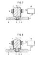
- Fig. 7 shows a body of a welding tool 1 formed from an insulating ceramic, and a conductive ceramic 7 is coated on that portion of the body, which include an area in contact with a bearing 4, to allow an electric current to flow.
- Sialon is used for the insulating ceramic.
- a welding tool 1 formed from tool steel is low in elevated temperature strength and so cannot be used.
- welding is made possible by the use of ceramic such as Sialon or the like.
- Sialon is an insulating ceramic, however, a current cannot be made to flow.
- a coating area of the conductive ceramic 7 is extended up to an area around the bearing 4 to allow an electric current to flow.
- welding can be performed on carbon steel of a high fusing point.
- the conductive ceramic 7 coated on surfaces of a shoulder 2 be increased to, for example, 5 to 10 ⁇ m in film thickness in order to expedite heating of the conductive ceramic in an area in contact with the workpieces 6.
- Fig. 8 shows an insulating ceramic 21 further coated on the surfaces of the shoulder 2 and the side of the pin 3 in the Embodiment 4.
- the shoulder 2 is increased in peripheral speed to be liable to involve much friction heat but it is possible according to the embodiment to prevent the surfaces of the shoulder 2 from rising excessively in welding temperature. That is, resistance heating is caused only in the vicinity of the tip end of the pin 3 whereby the number of revolutions of the welding tool 1 can be decreased as compared with conventional welding methods and so it is possible to prevent excessive heating in the vicinity of the surfaces of the shoulder 2.
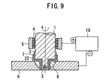
- Fig. 9 shows a welding tool 1, surfaces of which are coated with a conductive ceramic 7 and an abrasion-resistant ceramic 22. It is desired that Boron Nitride or the like be used as the abrasion-resistant ceramic 22. According to the embodiment, it is possible to improve durability of the welding tool 1.
Landscapes
- Engineering & Computer Science (AREA)
- Mechanical Engineering (AREA)
- Pressure Welding/Diffusion-Bonding (AREA)
Abstract
Description
- The present invention relates to a method of plugging a rotating welding tool into a weld zone of workpieces to perform friction stir welding, and a friction stir welding apparatus.
- Methods of solid-state welding two workpieces without melting include a welding method making use of a friction stir phenomenon caused by rotation of a welding tool, formed from a harder material than the workpieces, by rotating and plugging the welding tool into a weld zone of the workpieces and moving the welding tool along a welding direction, such method being called friction stir welding.
- Included among friction stir welding is one, in which an external heat source such as laser or the like preheats a weld zone and its neighborhood (for example, see Patent Document 1). Patent Document 1: JP-A-10-225781 (Abstract,
claim 1, figure 1) - In the case where temperature of a weld zone is raised only by friction heat generated between a welding tool and workpieces in friction stir welding, a very large friction force is generated in friction stir welding of thick plates or the like. When a friction force is large, workpieces become liable to be deformed, and a welding tool is shortened in life. Even when preheating is effected from outside by laser or the like, a friction force almost accounts for raising temperature of a weld zone. Therefore, a large friction force acts on a welding tool or workpieces as reaction thereof.
- The invention has its object to provide a method capable of decreasing generation of a friction force in friction stir welding, and an apparatus therefor.
- According to the invention, in friction stir welding, in which a welding tool is used, resistance heating is caused on the welding tool by flowing a current between workpieces and the welding tool. Combined use of resistance heating makes it possible to suppress generation of a friction force.
- In friction stir welding, since a metal is ordinarily used for a welding tool, resistance heating can be caused on the welding tool by flowing a current between workpieces and the welding tool. Preferably, however, a coating layer of a heater should be provided on surfaces of the tool so that the welding tool is made liable to cause resistance heating. A conductive ceramic can be used for the heater. Listed as a conductive ceramic applicable to the invention are Silicon Carbide (SiC), Titanium Nitride (TiN), Chromium Nitride (CrN), DLC (Diamond-like Carbon), Aluminum Nitride (AlN), Titanium Carbide (TiC), and so on, and most desirable among these materials in view of abrasion resistance, mechanical strength, toughness, and the like is Silicon Carbide or Diamond-like Carbon.
- CVD, PVD, plasma PVD, thermal spraying, or the like can be applied as a method of coating a conductive ceramic. It is preferable to select a coating method depending upon a material of ceramic. CVD is desirable in coating of Silicon Carbide.
- It is preferred that a coating thickness of a conductive ceramic is large since electric resistance is increased and a calorific value is increased, but coating takes much time when such thickness is large and non-coated portions are left when such thickness is small, so that such thickness in the range of 0.5 to 10 µm is generally desirable.
- With friction stir welding, a welding tool comprising a small-diameter pin provided on a tip end of a large-diameter shoulder is ordinarily used, and the pin is pressed and plugged into workpieces until the shoulder comes into contact with surfaces of the workpieces. The friction stir phenomenon is actively generated specifically on a portion of the shoulder and a side portion of the pin. Accordingly, it is desirable to increase a calorific value on the shoulder and the side of the pin, and it is effective as one of measures to coat a tip end portion of the pin with a ceramic, which is higher in conductivity than a ceramic formed on the shoulder and the side of the pin. Also, with friction stir welding, the tip end portion of the pin is particularly susceptible to abrasion, and so a ceramic having an excellent abrasion resistance is preferably used for a conductive ceramic formed particularly on the tip end portion of the pin.
- It is effective to coat a part of surfaces of the welding tool with an insulating ceramic and to coat the remainder of the surfaces with a conductive ceramic, and a concrete construction, function and effect in this case will be described in an embodiment described later.
- In embodying the invention, it is desirable to apply a constant voltage between a welding tool and workpieces. Also, it is desirable to control voltage and current flowing through the welding tool and workpieces in a manner to make a calorific value in resistance heating constant.
- A friction stir welding apparatus according to the invention is provided with a power supply device for flowing a current between a welding tool and workpieces. It is preferable to hold the welding tool with a spindle and to flow a current between the spindle and workpieces.
- The invention can be applied not only to welding of aluminum or aluminum alloy and copper or copper alloy but also to welding of high melting point metals, such as carbon steel, stainless steel, titanium, or the like. It can be said that the invention provides a method, which is specifically effective in welding of this kind of materials having a high melting point. The invention is also suited to friction stir welding of thick plates.
- Other objects, features and advantages of the invention will become apparent from the following description of the embodiments of the invention taken in conjunction with the accompanying drawings.
-
- Fig. 1 is a cross sectional view showing a welding state representative of an embodiment of the invention;
- Fig. 2 is a perspective view showing a welding method according to the invention;
- Fig. 3 is a graph indicating a comparison with respect to rotation torque of a welding tool between the invention and a conventional method;
- Fig. 4 is a graph indicating a comparison with respect to downward force between the embodiment and a conventional method;
- Fig. 5 is a cross sectional view showing a welding state representative of a further embodiment of the invention;
- Fig. 6 is a cross sectional view showing a welding state representative of a still further embodiment of the invention;
- Fig. 7 is a cross sectional view showing a welding state representative of a further embodiment of the invention;
- Fig. 8 is a cross sectional view showing a welding state representative of a still further embodiment of the invention; and
- Fig. 9 is a cross sectional view showing a welding state representative of a further embodiment of the invention.
-
- Fig. 1 is a cross sectional view showing a state, in which a welding tool is plugged into a welding zone of workpieces. Fig. 2 is a perspective view. However, illustration of a power supply device is omitted. A
welding tool 1 comprises a large-diameter shoulder 2 and a small-diameter pin 3. Thewelding tool 1 is press-fitted intoworkpieces 6 while rotating. In this state, welding is performed by moving thewelding tool 1 in a welding direction as shown in Fig. 2. Thewelding tool 1 is held by a bearing 4 and aspindle wall 5. Also, apower supply device 10 allows a current to flow between thespindle wall 5 and theworkpieces 6. - Rotation of the
welding tool 1 causes metal flow of theworkpieces 6 to form ametal flow zone 8. Themetal flow zone 8 may be considered to correspond to astir zone 11 shown in Fig. 2. - A conductive ceramic 7 is coated on that surface portion of the
welding tool 1, which contacts with theworkpieces 6. When thepower supply device 10 allows a current to flow between thespindle wall 5 and the workpieces, the conductive ceramic 7 causes resistance heating to raise temperature of a welding zone cooperating with friction heat. It is desired that a current flowing between the welding tool and the workpieces be constant in voltage. This is because the higher a welding temperature the larger a value of resistance of the conductive ceramic 7, a calorific value is the product of current and voltage, and with constant voltage, a control mechanism works such that when a value of resistance increases, a current value decreases and a calorific value itself decreases while a calorific value conversely increases when a welding temperature lowers. - In the case where it is necessary to accurately control a calorific value, it is desirable to measure current and voltage to perform welding while controlling voltage so as to obtain a predetermined calorific value. In addition, a current from the
power supply device 10 may be either of direct current and alternating current. Also, with direct current, the same effect is obtained no matter whether sides of theworkpieces 6 are made a positive electrode or a negative electrode. - According to the embodiment, aluminum alloy plates of JIS Standard 5052 and having a plate thickness of 5 mm were subjected to butt welding. Tool rotating
speed 1 was 400 rpm, and thewelding speed 1 was 600 mm/min. Tool steel was used for a material of thewelding tool 1, and silicon carbide forming the conductive ceramic 7 was coated on surfaces of the welding tool by means of CVD. The conductive ceramic 7 had a film thickness of 1 µm. Instead of making the film thickness constant, temperature of themetal flow zone 8 can be controlled by thickening a surface portion of theshoulder 2, from which a large amount of friction heat is generated, and thinning a surface portion of thepin 3 to increase an amount of resistance heat generated on the surface portion of thepin 3. - In the case where voltage is applied between the
welding tool 1 and theworkpieces 6 to cause resistance heating of theconductive ceramic 7, it is desired that a value of resistance of the conductive ceramic 7 be larger than a value of contact resistance between thebearing 4 and thewelding tool 1. This is because thebearing 4 is shortened in life when thebearing 4 causes resistance heating. In the case where it is anxious that thebearing 4 is decreased in life, it is also effective to perform welding while cooling thebearing 4 as by water cooling. - According to the invention, since a welding zone can be heated by both resistance heating and friction heat, it is possible to decrease torque, with which the
welding tool 1 is rotated, and to decrease a capacity of a motor for rotating thewelding tool 1. - Fig. 3 is a graph indicating a comparison with respect to rotation torque between the embodiment and a conventional method, in which a tool does not cause resistance heating. While rotation torque was as large as 50 Nm in the conventional method, rotation torque in the invention amounted to about one third of the rotation torque in the conventional method, that is, 15 Nm because the invention uses resistance heating in combination. Therefore, while a spindle motor having a rated capacity of 11 kW was needed in the conventional method, a motor having a rated capacity of 3.7 kW could accommodate the rotation torque in the invention and so it has become possible to make a motor small in size.
- Fig. 4 indicates a comparison with respect to a downward force between the method of the invention and a conventional method. Here, a downward force is a force acting in a direction along a plate thickness of the
workpieces 6. While the downward force was 20 kN in the conventional method, it was as small as 5 kN in the invention. Therefore, a motor for rotating thewelding tool 1 can be made small in size, and there is no need of increasing rigidity of the device, so that miniaturization and space-saving can be realized for the welding device. - In Fig. 5, only surfaces of the
pin 3 on thewelding tool 1 are coated with theconductive ceramic 7, and surfaces of theshoulder 2 are coated with an insulatingceramic 21. It is desired that Sialon, Silicon Nitride (Si3N4), or the like be used for the insulatingceramic 21. Also, the insulating ceramic may be the same in thickness and coating method as the conductive ceramic. In the embodiment, heat can be selectively generated only on surfaces of thepin 3 because the insulatingceramic 21 generates no heat. Generally, resistance heating is desirably generated on thepin 3 from a point of view that temperature should be prevented from rising excessively near theshoulder 2 because friction heat is generated in a higher ratio on the surfaces of theshoulder 2 than on the surfaces of thepin 3 due to a large peripheral speed of the shoulder. - Fig. 6 shows an embodiment, in which the insulating
ceramic 21 is coated on the surfaces of theshoulder 2 and a surface of a root of thepin 3 and theconductive ceramic 7 is coated on a tip end of the pin so that only the tip end of thepin 3 causes resistance heating. According to the embodiment, it is possible to control a temperature distribution in themetal flow zone 8. While a calorific value is much generated on the surfaces of theshoulder 2, which are largest in peripheral speed, in the conventional method and so temperature becomes too high in some cases, resistance heating is caused only at the tip end of thepin 3 in the embodiment, so that themetal flow zone 8 is made uniform in temperature to enable welding with no defect even when the welding speed is increased. - Fig. 7 shows a body of a
welding tool 1 formed from an insulating ceramic, and aconductive ceramic 7 is coated on that portion of the body, which include an area in contact with abearing 4, to allow an electric current to flow. For example, Sialon is used for the insulating ceramic. In the case where friction stir welding is to be performed on carbon steel or stainless steel, awelding tool 1 formed from tool steel is low in elevated temperature strength and so cannot be used. Thus welding is made possible by the use of ceramic such as Sialon or the like. In this case, since Sialon is an insulating ceramic, however, a current cannot be made to flow. Hereupon, a coating area of theconductive ceramic 7 is extended up to an area around thebearing 4 to allow an electric current to flow. According to the embodiment, welding can be performed on carbon steel of a high fusing point. In addition, it is desired in this case that the conductive ceramic 7 coated on surfaces of ashoulder 2 be increased to, for example, 5 to 10 µm in film thickness in order to expedite heating of the conductive ceramic in an area in contact with theworkpieces 6. - Fig. 8 shows an insulating
ceramic 21 further coated on the surfaces of theshoulder 2 and the side of thepin 3 in theEmbodiment 4. In the case of welding of carbon steel, theshoulder 2 is increased in peripheral speed to be liable to involve much friction heat but it is possible according to the embodiment to prevent the surfaces of theshoulder 2 from rising excessively in welding temperature. That is, resistance heating is caused only in the vicinity of the tip end of thepin 3 whereby the number of revolutions of thewelding tool 1 can be decreased as compared with conventional welding methods and so it is possible to prevent excessive heating in the vicinity of the surfaces of theshoulder 2. Thereby, even in the case of welding of carbon steel, it is possible to uniformize themetal flow zone 8 in temperature distribution to prevent generation of a defect such as deformation or the like. - Fig. 9 shows a
welding tool 1, surfaces of which are coated with aconductive ceramic 7 and an abrasion-resistant ceramic 22. It is desired that Boron Nitride or the like be used as the abrasion-resistant ceramic 22. According to the embodiment, it is possible to improve durability of thewelding tool 1. - According to the invention, it has become possible to decrease generation of friction forces in friction stir welding.
- It should be further understood by those skilled in the art that although the foregoing description has been made on embodiments of the invention, the invention is not limited thereto and various changes and modifications may be made without departing from the spirit of the invention and the scope of the appended claims.
Claims (18)
- A method of friction stir welding workpieces together by rotating and plugging a welding tool (1), formed from a harder material than the workpieces (6), into a weld zone of the workpieces and moving the welding tool relatively in a welding direction, characterized in that a current is allowed to flow between said welding tool (1) and said workpieces (6) to cause resistance heating of said welding tool.
- A method of friction stir welding workpieces together by rotating and pressing a welding tool, formed from a harder material than the workpieces, into a weld zone of the workpieces and moving the welding tool relatively in a welding direction, characterized in that a coating layer (7) of a heater is formed on at least that portion of said welding tool (1), which is plugged into the workpieces (1), and a current is allowed to flow between said welding tool and the workpieces to cause resistance heating of said heater.
- The friction stir welding method according to claim 2, wherein said heater comprises a conductive ceramic (7).
- The friction stir welding method according to claim 3, wherein said conductive ceramic comprises Silicon Carbide.
- The friction stir welding method according to claim 2, wherein said welding tool comprises a small-diameter pin (3) on a tip end of a large-diameter shoulder (2, surfaces of said pin are covered with said heater (7), and surfaces of said shoulder are covered with an insulating ceramic (21).
- The friction stir welding method according to claim 2, wherein said welding tool (1) comprises a small-diameter pin (3) on a tip end of a large-diameter shoulder (2), a tip end portion of said pin is covered with said heater (7), and the remainder of said pin and surfaces of said shoulder are covered with an insulating ceramic (21).
- The friction stir welding method according to claim 2, wherein said welding tool (1) is formed from an insulating ceramic and surfaces of said tool are covered with said heater (7).
- The friction stir welding method according to claim 2, wherein said welding tool (1) comprises a small-diameter pin (3) on a tip end of a large-diameter shoulder (2), all surfaces of said pin and surfaces of said shoulder are covered with said heater (7), and further a coating layer of an insulating ceramic (21) is formed on an outside of said heater (7) except a tip end portion of said pin (3).
- The friction stir section stir welding method according to claim 3, wherein an outside of a coating layer formed from said conductive ceramic is further covered with a ceramic having a high conductivity.
- The friction stir welding method according to claim 9, wherein said ceramic (21) formed on an outermost surface of said welding tool (1) comprises a material having a more excellent abrasion resistance than that of said conductive ceramic (1, 7) formed therebelow.
- The friction stir welding method according to claim 3, wherein said welding tool (1) comprises a small-diameter pin (3) on a tip end of a large-diameter shoulder (2), materials of a ceramic (7), which covers a tip end portion of said pin (3), and of a ceramic (21), which covers a side portion of said pin (3) and surfaces of said shoulder (2), are different from each other, and the ceramic (7) covering the tip end portion of said pin is increased in conductivity.
- The friction stir welding method according to claim 1, wherein the current allowed to flow between said welding tool (1) and said workpieces (6) is controlled to be made constant in voltage.
- The friction stir welding method according to claim 2, wherein the current allowed to flow between the welding tool and the workpieces is controlled to be made constant in voltage.
- The friction stir welding method according to claim 2, wherein voltage or current is controlled so that said heater (7) has a constant calorific value.
- A friction stir welding apparatus for performing friction stir welding by rotating and pressing a welding tool (1), formed from a harder material than workpieces, into a weld zone (8) of the workpieces (6) and moving the welding tool relatively in a welding direction, wherein there is provided a power supply device (10), which allows an electric current to flow between the welding tool (1) and the workpieces (6) to cause resistance heating of the welding tool.
- The friction stir welding apparatus according to claim 15, wherein a coating layer (7) of a heater is formed on at least a portion of said welding tool (1); which is plugged into the workpieces (6), and said heater causes resistance heating when an electric current is allowed to flow between said welding tool and said workpieces.
- The friction stir welding apparatus according to claim 16, wherein said heater comprises a conductive ceramic.
- The friction stir welding apparatus according to claim 15, wherein said welding tool is held by a spindle, and said power supply device allows an electric current to flow between said spindle and said workpieces.
Applications Claiming Priority (2)
| Application Number | Priority Date | Filing Date | Title |
|---|---|---|---|
| JP2002369160A JP2004195525A (en) | 2002-12-20 | 2002-12-20 | Friction stir welding method |
| JP2002369160 | 2002-12-20 |
Publications (2)
| Publication Number | Publication Date |
|---|---|
| EP1430986A1 true EP1430986A1 (en) | 2004-06-23 |
| EP1430986B1 EP1430986B1 (en) | 2007-04-11 |
Family
ID=32376312
Family Applications (1)
| Application Number | Title | Priority Date | Filing Date |
|---|---|---|---|
| EP03004933A Expired - Lifetime EP1430986B1 (en) | 2002-12-20 | 2003-03-07 | Friction stir welding method and apparatus for reducing the friction force |
Country Status (4)
| Country | Link |
|---|---|
| US (1) | US6866181B2 (en) |
| EP (1) | EP1430986B1 (en) |
| JP (1) | JP2004195525A (en) |
| DE (1) | DE60313110T2 (en) |
Cited By (9)
| Publication number | Priority date | Publication date | Assignee | Title |
|---|---|---|---|---|
| EP1716959A3 (en) * | 2005-04-28 | 2006-12-06 | Hydro Aluminium Deutschland GmbH | Process of and devices for friction stir welding of at least two Workpieces of different materials with a slidable pin and current passing through the workpieces |
| GB2403444B (en) * | 2003-07-01 | 2007-10-24 | Res Inst Ind Science & Tech | Tool, apparatus, and method for welding workpieces |
| EP1882543A1 (en) | 2006-07-28 | 2008-01-30 | Kawasaki Jukogyo Kabushiki Kaisha | Friction stir welding machine and friction stir welding tool, the portion of the tool being in contact with the materials to be welded being coated with aluminium nitride |
| CN101323054B (en) * | 2007-11-09 | 2010-09-01 | 罗键 | Electric conduction-stirring friction composite heat power supply welding method and equipment |
| CN101537529B (en) * | 2009-04-24 | 2011-03-30 | 重庆大学 | Pin tool for friction stir welding and ultrafine grain preparation method thereof |
| CN105436697A (en) * | 2015-12-02 | 2016-03-30 | 浙江理工大学 | Efficient heat-insulation friction stir welding head and method |
| DE102016110813B4 (en) * | 2016-06-13 | 2021-02-11 | Kumatec Sondermaschinenbau & Kunststoffverarbeitung Gmbh | Method for preventing sticking and contamination of resistance welding electrodes during resistance welding |
| US11772188B1 (en) * | 2021-11-04 | 2023-10-03 | Lockheed Martin Corporation | Additive friction stir deposition system for refractory metals |
| US12269110B2 (en) * | 2023-01-26 | 2025-04-08 | Goodrich Corporation | Field-assisted friction stir additive manufacturing |
Families Citing this family (47)
| Publication number | Priority date | Publication date | Assignee | Title |
|---|---|---|---|---|
| CN1191144C (en) * | 2000-05-08 | 2005-03-02 | 布莱阿姆青年大学 | Superabrasive tools and methods for friction stir welding |
| JP2004195525A (en) * | 2002-12-20 | 2004-07-15 | Hitachi Ltd | Friction stir welding method |
| WO2005084162A2 (en) * | 2003-08-04 | 2005-09-15 | Smith International, Inc. | Crack repair using friction stir welding on materials including metal matrix composites, ferrous alloys, non-ferrous alloys, and superalloys |
| US7121448B2 (en) * | 2003-08-29 | 2006-10-17 | General Electric Company | Friction stir welding apparatus and associated thermal management systems and methods |
| JP5180471B2 (en) * | 2004-04-30 | 2013-04-10 | 株式会社総合車両製作所 | Metal joining method |
| US7275675B1 (en) * | 2004-08-20 | 2007-10-02 | United States Of America As Represented By The Administrator Of The National Aeronautics And Space Administration | Friction stir weld tools |
| JP4468125B2 (en) * | 2004-09-27 | 2010-05-26 | 三菱重工業株式会社 | Friction stir welding method and apparatus |
| CA2582732C (en) * | 2004-10-05 | 2012-09-11 | Sii Megadiamond, Inc. | Expandable mandrel for use in friction stir welding |
| US7078647B2 (en) * | 2004-10-21 | 2006-07-18 | Wisconsin Alumni Research Foundation | Arc-enhanced friction stir welding |
| JP4643319B2 (en) * | 2005-03-15 | 2011-03-02 | 株式会社東芝 | COMPOSITE MATERIAL, ITS MANUFACTURING METHOD, AND COMPOSITE MATERIAL MANUFACTURING DEVICE |
| US8632850B2 (en) | 2005-09-26 | 2014-01-21 | Schultz-Creehan Holdings, Inc. | Friction fabrication tools |
| US20080041921A1 (en) | 2005-09-26 | 2008-02-21 | Kevin Creehan | Friction stir fabrication |
| US8875976B2 (en) | 2005-09-26 | 2014-11-04 | Aeroprobe Corporation | System for continuous feeding of filler material for friction stir welding, processing and fabrication |
| US9511446B2 (en) | 2014-12-17 | 2016-12-06 | Aeroprobe Corporation | In-situ interlocking of metals using additive friction stir processing |
| US9511445B2 (en) | 2014-12-17 | 2016-12-06 | Aeroprobe Corporation | Solid state joining using additive friction stir processing |
| US9266191B2 (en) | 2013-12-18 | 2016-02-23 | Aeroprobe Corporation | Fabrication of monolithic stiffening ribs on metallic sheets |
| US8056797B2 (en) * | 2005-10-05 | 2011-11-15 | Megastir Technologies | Expandable mandrel for use in friction stir welding |
| US8550326B2 (en) | 2005-10-05 | 2013-10-08 | Megastir Technologies Llc | Expandable mandrel for use in friction stir welding |
| US8141768B2 (en) | 2006-01-27 | 2012-03-27 | Exxonmobil Research And Engineering Company | Application of high integrity welding and repair of metal components in oil and gas exploration, production and refining |
| JP2007237282A (en) * | 2006-03-10 | 2007-09-20 | Osaka Univ | Metal joining method |
| GB0609669D0 (en) * | 2006-05-15 | 2006-06-28 | Welding Inst | Friction stir method |
| JP5099009B2 (en) * | 2006-08-21 | 2012-12-12 | 国立大学法人大阪大学 | Metal processing method and structure |
| US8466386B2 (en) * | 2006-10-10 | 2013-06-18 | GM Global Technology Operations LLC | Method for repairing bonded metallic structures |
| JP4919910B2 (en) * | 2007-09-18 | 2012-04-18 | 川崎重工業株式会社 | Friction stir welding apparatus and friction stir welding tool |
| JP5149607B2 (en) * | 2007-12-13 | 2013-02-20 | 株式会社日立製作所 | Friction stirrer and friction stir process |
| US8164021B1 (en) * | 2008-03-31 | 2012-04-24 | The United States Of America As Represented By The Secretary Of The Navy | Electrically assisted friction stir welding |
| GB2478480B (en) * | 2008-12-24 | 2014-04-30 | Japan Transp Engineering Company | Metal material processing method and rotary tool |
| JP2010194591A (en) * | 2009-02-26 | 2010-09-09 | Kyocera Corp | Tool and apparatus for friction stir welding |
| CA2779075C (en) * | 2009-11-02 | 2016-05-10 | Megastir Technologies Llc | Out of position friction stir welding of casing and small diameter tubing or pipe |
| EP2514552A4 (en) | 2009-12-17 | 2017-04-05 | Sumitomo Electric Industries, Ltd. | Coated rotary tool |
| US9297795B2 (en) * | 2010-12-03 | 2016-03-29 | Todd Nicholas Bishop | Monitored filament insertion for resitivity testing |
| WO2013002869A2 (en) | 2011-04-07 | 2013-01-03 | Schultz-Creehan Holdings, Inc. | System for continuous feeding of filler material for friction stir fabrication and self-reacting friction stir welding tool |
| JP2013000773A (en) * | 2011-06-16 | 2013-01-07 | Sumitomo Electric Ind Ltd | Coated rotating tool |
| US8899467B1 (en) * | 2011-09-23 | 2014-12-02 | The United States Of America As Represented By The Administrator Of The National Aeronautics And Space Administration | Ultrasonically-assisted thermal stir welding system |
| CN103212781A (en) * | 2013-04-28 | 2013-07-24 | 江苏科技大学 | High frequency contact-stirring friction hybrid welding device and welding method |
| US9981338B2 (en) * | 2014-06-26 | 2018-05-29 | The Regents Of The University Of Michigan | Hybrid friction stir welding for dissimilar materials through electro-plastic effect |
| DE102015005407A1 (en) * | 2015-04-29 | 2016-11-03 | Airbus Defence and Space GmbH | Friction stir welding of thermoplastics |
| CN106825908A (en) * | 2017-03-10 | 2017-06-13 | 东北大学 | A kind of device and method without keyhole agitating friction weldering slab |
| WO2019089764A1 (en) | 2017-10-31 | 2019-05-09 | Aeroprobe Corporation | Solid-state additive manufacturing system and material compositions and structures |
| CN108890119A (en) * | 2018-09-20 | 2018-11-27 | 北京工业大学 | Controllable current distribution current-carrying friction stir welding method |
| CN112139656A (en) * | 2020-09-30 | 2020-12-29 | 中国兵器工业第五九研究所 | Current-assisted friction additive manufacturing device and method |
| US11958126B2 (en) * | 2020-10-06 | 2024-04-16 | GE Precision Healthcare LLC | Containers for retaining anesthetic agent and manufacturing methods thereof |
| JP7579763B2 (en) * | 2021-07-16 | 2024-11-08 | 本田技研工業株式会社 | Joining device and joining method for friction stir welding and resistance welding |
| JP7353329B2 (en) * | 2021-07-16 | 2023-09-29 | 本田技研工業株式会社 | Welding device and method for friction stir welding and resistance welding |
| AT525908B1 (en) * | 2022-10-24 | 2023-09-15 | Royos Joining Solutions Gmbh | Stir welding device for producing a welded connection |
| FR3155729A1 (en) * | 2023-11-27 | 2025-05-30 | Institut Maupertuis | Friction stir welding tool including improved shoulder |
| DE102024130943A1 (en) | 2024-10-23 | 2026-04-23 | Kuka Deutschland Gmbh | Method for producing a weld seam using a robot-guided friction stir welding tool, friction stir welding device and computer program product |
Citations (5)
| Publication number | Priority date | Publication date | Assignee | Title |
|---|---|---|---|---|
| EP0653265A2 (en) * | 1991-12-06 | 1995-05-17 | The Welding Institute | Improvements relating to friction welding |
| US5829664A (en) * | 1996-11-15 | 1998-11-03 | Aluminum Company Of America | Resistance heated stir welding |
| EP1151820A2 (en) * | 2000-05-03 | 2001-11-07 | The BOC Group plc | Improvements in thermal welding |
| US20020014516A1 (en) * | 2000-05-08 | 2002-02-07 | Nelson Tracy W. | Friction stir welding of metal matrix composites, ferrous alloys, non-ferrous alloys, and superalloys using a superabrasive tool |
| JP2002239754A (en) * | 2001-02-15 | 2002-08-28 | Hitachi Ltd | Friction stir welding method and apparatus |
Family Cites Families (8)
| Publication number | Priority date | Publication date | Assignee | Title |
|---|---|---|---|---|
| JPH0814345B2 (en) | 1987-03-11 | 1996-02-14 | 大阪瓦斯株式会社 | Piping method |
| AU2001262980A1 (en) * | 2000-05-05 | 2001-11-20 | Brigham Young University | Friction stir welding of polymeric materials |
| DE10036170C1 (en) * | 2000-07-25 | 2001-12-06 | Eads Deutschland Gmbh | Laser-supported friction welding process comprises pressing side surfaces of the workpieces so that they touch the workpiece surface moving away from the welding probe and are spaced in the central region up to the workpiece surface |
| US6780525B2 (en) * | 2001-12-26 | 2004-08-24 | The Boeing Company | High strength friction stir welding |
| US6726085B2 (en) * | 2002-05-14 | 2004-04-27 | The Boeing Company | Method and apparatus for producing a refined grain structure |
| US6776328B2 (en) * | 2002-09-17 | 2004-08-17 | The Boeing Company | Radiation assisted friction welding |
| JP2004195525A (en) * | 2002-12-20 | 2004-07-15 | Hitachi Ltd | Friction stir welding method |
| US6913186B2 (en) * | 2003-09-11 | 2005-07-05 | The Boeing Company | Apparatus and method for friction stir welding with a variable speed pin |
-
2002
- 2002-12-20 JP JP2002369160A patent/JP2004195525A/en active Pending
-
2003
- 2003-03-06 US US10/379,670 patent/US6866181B2/en not_active Expired - Fee Related
- 2003-03-07 EP EP03004933A patent/EP1430986B1/en not_active Expired - Lifetime
- 2003-03-07 DE DE60313110T patent/DE60313110T2/en not_active Expired - Fee Related
Patent Citations (5)
| Publication number | Priority date | Publication date | Assignee | Title |
|---|---|---|---|---|
| EP0653265A2 (en) * | 1991-12-06 | 1995-05-17 | The Welding Institute | Improvements relating to friction welding |
| US5829664A (en) * | 1996-11-15 | 1998-11-03 | Aluminum Company Of America | Resistance heated stir welding |
| EP1151820A2 (en) * | 2000-05-03 | 2001-11-07 | The BOC Group plc | Improvements in thermal welding |
| US20020014516A1 (en) * | 2000-05-08 | 2002-02-07 | Nelson Tracy W. | Friction stir welding of metal matrix composites, ferrous alloys, non-ferrous alloys, and superalloys using a superabrasive tool |
| JP2002239754A (en) * | 2001-02-15 | 2002-08-28 | Hitachi Ltd | Friction stir welding method and apparatus |
Non-Patent Citations (1)
| Title |
|---|
| PATENT ABSTRACTS OF JAPAN vol. 2002, no. 12 12 December 2002 (2002-12-12) * |
Cited By (11)
| Publication number | Priority date | Publication date | Assignee | Title |
|---|---|---|---|---|
| GB2403444B (en) * | 2003-07-01 | 2007-10-24 | Res Inst Ind Science & Tech | Tool, apparatus, and method for welding workpieces |
| EP1716959A3 (en) * | 2005-04-28 | 2006-12-06 | Hydro Aluminium Deutschland GmbH | Process of and devices for friction stir welding of at least two Workpieces of different materials with a slidable pin and current passing through the workpieces |
| EP1882543A1 (en) | 2006-07-28 | 2008-01-30 | Kawasaki Jukogyo Kabushiki Kaisha | Friction stir welding machine and friction stir welding tool, the portion of the tool being in contact with the materials to be welded being coated with aluminium nitride |
| US7828191B2 (en) | 2006-07-28 | 2010-11-09 | Kawasaki Jukogyo Kabushiki Kaisha | Friction stir welding machine and friction stir welding tool |
| US8025200B2 (en) | 2006-07-28 | 2011-09-27 | Kawasaki Jukogyo Kabushiki Kaisha | Friction stir welding machine and friction stir welding tool |
| CN101323054B (en) * | 2007-11-09 | 2010-09-01 | 罗键 | Electric conduction-stirring friction composite heat power supply welding method and equipment |
| CN101537529B (en) * | 2009-04-24 | 2011-03-30 | 重庆大学 | Pin tool for friction stir welding and ultrafine grain preparation method thereof |
| CN105436697A (en) * | 2015-12-02 | 2016-03-30 | 浙江理工大学 | Efficient heat-insulation friction stir welding head and method |
| DE102016110813B4 (en) * | 2016-06-13 | 2021-02-11 | Kumatec Sondermaschinenbau & Kunststoffverarbeitung Gmbh | Method for preventing sticking and contamination of resistance welding electrodes during resistance welding |
| US11772188B1 (en) * | 2021-11-04 | 2023-10-03 | Lockheed Martin Corporation | Additive friction stir deposition system for refractory metals |
| US12269110B2 (en) * | 2023-01-26 | 2025-04-08 | Goodrich Corporation | Field-assisted friction stir additive manufacturing |
Also Published As
| Publication number | Publication date |
|---|---|
| US6866181B2 (en) | 2005-03-15 |
| US20040118899A1 (en) | 2004-06-24 |
| JP2004195525A (en) | 2004-07-15 |
| EP1430986B1 (en) | 2007-04-11 |
| DE60313110D1 (en) | 2007-05-24 |
| DE60313110T2 (en) | 2007-12-20 |
Similar Documents
| Publication | Publication Date | Title |
|---|---|---|
| US6866181B2 (en) | Friction stir welding method | |
| JP4869817B2 (en) | Friction stir welding equipment | |
| US6732901B2 (en) | Anvil for friction stir welding high temperature materials | |
| JP2002336974A (en) | Ultrasonic welding equipment | |
| CN114206535A (en) | Solid-phase bonding method for dissimilar materials and solid-phase bonded structure of dissimilar materials | |
| EP1399286A1 (en) | Anvil for friction stir welding high temperature materials | |
| JP6024739B2 (en) | Coated rotating tool and manufacturing method thereof | |
| US11534854B2 (en) | Friction stir welding tool and friction stir welding method | |
| CN106624406A (en) | Welding method for ultra-fine particle hard alloy cutter | |
| CN107530817B (en) | Improved welding electrode cap | |
| US20150129638A1 (en) | Friction Stir Welding Tool and Method for the Production Thereof | |
| AU2021223858A1 (en) | Friction stir welding tool and method for producing same | |
| CA1308175C (en) | Electrodes for use in spot welding | |
| CN219131102U (en) | Molecular diffusion welding machine | |
| JP2003311441A (en) | Friction stir welding method | |
| JP2007268543A (en) | Friction stir welding equipment | |
| JPH06285645A (en) | Contact tip for welding | |
| JP2015006688A (en) | Resistance welding electrode | |
| JP5942034B2 (en) | Friction stir welding apparatus and joining method | |
| JP7374836B2 (en) | How to join metal parts | |
| CN223260040U (en) | Heating roller of fixer and laser printer | |
| JP7002097B1 (en) | Electrode tip | |
| JPH10240058A (en) | Thermal fixing roller | |
| JP2019155394A (en) | Friction agitation welding method and friction agitation welding device | |
| JP2006130514A (en) | Electrode for spot welding |
Legal Events
| Date | Code | Title | Description |
|---|---|---|---|
| PUAI | Public reference made under article 153(3) epc to a published international application that has entered the european phase |
Free format text: ORIGINAL CODE: 0009012 |
|
| AK | Designated contracting states |
Kind code of ref document: A1 Designated state(s): AT BE BG CH CY CZ DE DK EE ES FI FR GB GR HU IE IT LI LU MC NL PT RO SE SI SK TR |
|
| AX | Request for extension of the european patent |
Extension state: AL LT LV MK |
|
| 17P | Request for examination filed |
Effective date: 20041014 |
|
| AKX | Designation fees paid |
Designated state(s): DE FR GB |
|
| 17Q | First examination report despatched |
Effective date: 20050627 |
|
| GRAP | Despatch of communication of intention to grant a patent |
Free format text: ORIGINAL CODE: EPIDOSNIGR1 |
|
| RTI1 | Title (correction) |
Free format text: FRICTION STIR WELDING METHOD AND APPARATUS FOR REDUCING THE FRICTION FORCE |
|
| GRAS | Grant fee paid |
Free format text: ORIGINAL CODE: EPIDOSNIGR3 |
|
| GRAA | (expected) grant |
Free format text: ORIGINAL CODE: 0009210 |
|
| RAP1 | Party data changed (applicant data changed or rights of an application transferred) |
Owner name: HITACHI, LTD. |
|
| RIN1 | Information on inventor provided before grant (corrected) |
Inventor name: SATO, KOUJI,H Inventor name: OKAMURA, HISANORI,H Inventor name: AOTA, KINYA,H |
|
| AK | Designated contracting states |
Kind code of ref document: B1 Designated state(s): DE FR GB |
|
| REG | Reference to a national code |
Ref country code: GB Ref legal event code: FG4D |
|
| REF | Corresponds to: |
Ref document number: 60313110 Country of ref document: DE Date of ref document: 20070524 Kind code of ref document: P |
|
| PLBE | No opposition filed within time limit |
Free format text: ORIGINAL CODE: 0009261 |
|
| STAA | Information on the status of an ep patent application or granted ep patent |
Free format text: STATUS: NO OPPOSITION FILED WITHIN TIME LIMIT |
|
| 26N | No opposition filed |
Effective date: 20080114 |
|
| PGFP | Annual fee paid to national office [announced via postgrant information from national office to epo] |
Ref country code: GB Payment date: 20090219 Year of fee payment: 7 |
|
| PGFP | Annual fee paid to national office [announced via postgrant information from national office to epo] |
Ref country code: DE Payment date: 20090219 Year of fee payment: 7 |
|
| PGFP | Annual fee paid to national office [announced via postgrant information from national office to epo] |
Ref country code: FR Payment date: 20090217 Year of fee payment: 7 |
|
| GBPC | Gb: european patent ceased through non-payment of renewal fee |
Effective date: 20100307 |
|
| REG | Reference to a national code |
Ref country code: FR Ref legal event code: ST Effective date: 20101130 |
|
| PG25 | Lapsed in a contracting state [announced via postgrant information from national office to epo] |
Ref country code: FR Free format text: LAPSE BECAUSE OF NON-PAYMENT OF DUE FEES Effective date: 20100331 |
|
| PG25 | Lapsed in a contracting state [announced via postgrant information from national office to epo] |
Ref country code: DE Free format text: LAPSE BECAUSE OF NON-PAYMENT OF DUE FEES Effective date: 20101001 |
|
| PG25 | Lapsed in a contracting state [announced via postgrant information from national office to epo] |
Ref country code: GB Free format text: LAPSE BECAUSE OF NON-PAYMENT OF DUE FEES Effective date: 20100307 |