EP1430828A1 - Endoscope hood - Google Patents
Endoscope hood Download PDFInfo
- Publication number
- EP1430828A1 EP1430828A1 EP03715782A EP03715782A EP1430828A1 EP 1430828 A1 EP1430828 A1 EP 1430828A1 EP 03715782 A EP03715782 A EP 03715782A EP 03715782 A EP03715782 A EP 03715782A EP 1430828 A1 EP1430828 A1 EP 1430828A1
- Authority
- EP
- European Patent Office
- Prior art keywords
- endoscope
- distal end
- attachment
- end portion
- hood
- Prior art date
- Legal status (The legal status is an assumption and is not a legal conclusion. Google has not performed a legal analysis and makes no representation as to the accuracy of the status listed.)
- Granted
Links
Images


Classifications
-
- A—HUMAN NECESSITIES
- A61—MEDICAL OR VETERINARY SCIENCE; HYGIENE
- A61B—DIAGNOSIS; SURGERY; IDENTIFICATION
- A61B1/00—Instruments for performing medical examinations of the interior of cavities or tubes of the body by visual or photographical inspection, e.g. endoscopes; Illuminating arrangements therefor
- A61B1/00064—Constructional details of the endoscope body
- A61B1/00071—Insertion part of the endoscope body
- A61B1/0008—Insertion part of the endoscope body characterised by distal tip features
- A61B1/00089—Hoods
-
- A—HUMAN NECESSITIES
- A61—MEDICAL OR VETERINARY SCIENCE; HYGIENE
- A61B—DIAGNOSIS; SURGERY; IDENTIFICATION
- A61B1/00—Instruments for performing medical examinations of the interior of cavities or tubes of the body by visual or photographical inspection, e.g. endoscopes; Illuminating arrangements therefor
- A61B1/00002—Operational features of endoscopes
- A61B1/00043—Operational features of endoscopes provided with output arrangements
- A61B1/00055—Operational features of endoscopes provided with output arrangements for alerting the user
-
- A—HUMAN NECESSITIES
- A61—MEDICAL OR VETERINARY SCIENCE; HYGIENE
- A61B—DIAGNOSIS; SURGERY; IDENTIFICATION
- A61B1/00—Instruments for performing medical examinations of the interior of cavities or tubes of the body by visual or photographical inspection, e.g. endoscopes; Illuminating arrangements therefor
- A61B1/00064—Constructional details of the endoscope body
- A61B1/00071—Insertion part of the endoscope body
- A61B1/0008—Insertion part of the endoscope body characterised by distal tip features
- A61B1/00101—Insertion part of the endoscope body characterised by distal tip features the distal tip features being detachable
Definitions
- the present invention relates to an endoscope hood which is attached to a distal end portion of an endoscope insertion portion by press fitting.
- observation may be carried out with a cylindrical endoscope hood being attached to a distal end portion of an endoscope insertion portion.
- Jpn. Pat. Appln. KOKAI Publication No. 2001-224550 discloses a technique which prevents a protrusion portion which protrudes in an observation visual field direction on an distal end of a hood main body from being displayed on an endoscope observation image.
- the hood according to this technique has at least a part of the protrusion portion formed into an angular shape along an outer edge of an observation visual field or a shape that an end is partially cut so as to prevent an observation visual field from being obscured.
- the endoscope hood has a hood main body formed of a soft material such as a rubber. Such a hood is fixed by elastically deforming the cylindrical hood main body and press-fitting a fitting hole portion of the hood main body to a distal end portion of the endoscope insertion portion. Therefore, it is possible to attach a hood with a size other than an appropriate size such that an inside diametric dimension of the fitting hole portion (inner peripheral surface) of the hood main body fitted onto the distal end portion of the endoscope insertion portion is set to an appropriate dimension with respect to an outside diametric dimension of the distal end portion of the insertion.
- the hood can be attached to the distal end portion of the endoscope insertion portion.
- the hood main body receives an excessive force from the distal end portion of the endoscope insertion portion in, e.g., a hood attachment operation.
- a pressure welding force of the hood main body to the distal end portion of the endoscope insertion portion is strong, and it is hard to detach the hood. Therefore, when removing the hood from the distal end portion of the endoscope insertion portion, a large force may possibly be applied to the distal end portion of the endoscope insertion portion.
- the hood when the hood is elastically deformed and the hood is attached to a distal end portion of an endoscope insertion portion having an outside diameter (model) different from that of an endoscope insertion portion having an appropriate outside diameter, it is hard to judge whether this outside diameter is an endoscope insertion portion outside diameter which enables attachment by taking a deformation quantity of the hood into consideration. Furthermore, even if a hood which is produced for a distal end portion of a predetermined endoscope insertion portion is used, it may fit a distal end portion of another endoscope insertion portion, and it is difficult to judge the compatibility of the hood relative to an arbitrary endoscope insertion portion.
- the endoscope hood has: a cylindrical attachment portion which is attached in a state that an attachment position is positioned to the distal end portion of the insertion portion in a predetermined direction; a cylindrical protrusion portion which is formed on an end side of this attachment portion and protrudes from the distal end portion of the insertion portion of the endoscope to a front side; and attachment state confirming means for judging whether an attachment state of the attachment portion to the distal end portion of the insertion portion of the endoscope is appropriate or inappropriate based on an area of the protrusion portion displayed on an observation image of the endoscope, and giving a warning.
- the endoscope hood has: a cylindrical attachment portion which can be attached to an end portion of an insertion portion of a second endoscope which has an outside diameter appropriate to attachment to a predetermined position, which can be attached to an end portion of an insertion portion of a first endoscope, has an outside diameter different from that of the distal end portion of the insertion portion of the first endoscope; and a protrusion portion which is formed on an end side of this attachment portion, protrudes from end portions of the insertion portions of the first and second endoscopes in an observation visual field direction, and has an area displayed in an observation image of the second endoscope larger than an area displayed in an observation image of the first endoscope.
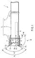
- FIG. 1 shows a distal end part of a direct vision type endoscope 1 which views in a front direction.
- FIG. 2 shows an end part of an endoscope (which may be referred to as a first endoscope 1a hereinafter) when a later-described hood 10 having an appropriate size relative to the endoscope 1 depicted in FIG. 1 is attached.
- a later-described insertion portion 5a of the first endoscope 1a has the same structure as a later-described insertion portion 5. It is determined that insertion portions 5b and 5c of later-described second and third endoscopes 1b and 1c are different in arrangement position but have the same constituent elements as those of the insertion portion 5 for the sake of convenience.
- the insertion portion 5 of the endoscope 1 includes a hard distal end portion 2, a bendable bending portion 3 connected to a proximal end portion of the distal end portion 2, and a soft portion 4 which is connected to a proximal end portion of this bending portion 3 and has the flexibility in the mentioned order from the end side.
- An end surface of the distal end portion 2, i.e., a distal end surface 2a of the insertion portion 5 is formed flat so as to be orthogonal to an axial direction of the distal end portion 2.
- the end portion 2 and the bending portion 3 are connected to each other through a ring-shaped first connection portion 7, and the bending portion 3 and the soft portion 4 are likewise connected to each other through a ring-shaped second connection portion 8.
- an insertion portion 5 are inserted, e.g., an endo-therapy accessory channel 6 indicated by a broken line in FIG. 1, an illumination optical system, an observation optical system, and a plurality of elements such as an air supply/water supply path.
- Various kinds of treatment tools such as a grasping forceps are inserted into the endo-therapy accessory channel 6.
- the illumination optical system guides a light ray from a light source device (not shown) on the proximal end portion side of the insertion portion and leads it to the distal end portion of the endoscope 1.
- the observation optical system is used to observe an analyte, which is illuminated by the illumination optical system, at the distal end portion 2a of the insertion portion 5 of the endoscope 1.
- An observation image at the distal end portion 2a is displayed in an observation image display portion 14 provided to the monitor device 13 which is connected to the proximal end portion side of the insertion portion 5 and shown in FIG. 3.
- an opening portion of the endo-therapy accessory channel 6 which is generally the largest element on this end surface 2a is opened on the rather lower side away from the center of the distal end surface 2a.
- On this end surface 2a are provided a pair of illumination lenses 19 disposed at the end of the illumination optical system and a circular object lens 9 provided at the end of an object optical system.
- Each of the illumination lenses 19 is arranged in the right or left direction with respect to the center of the distal end surface 2a and on the upper side away from the endo-therapy accessory channel 6.
- the object lens 9 is arranged on the rather upper side with respect to the center.
- a mask 9a which assures a visual field area having a substantially square shape such as indicated by a broken line in FIG. 2 is applied on this object lens 9. That is, the circular object lens 9 has a circumference thereof being covered while the substantially square visual field area is assured at the center thereof.
- a field angle of this object lens 9 is A1 in an opposite side direction corresponding to the observation image display portion 14 of the monitor device 13, and it is A2 in a diagonal direction. Visible field areas of these field angles A1 and A2 are different from each other (A1 ⁇ A2). Meanwhile, it is assumed that the maximum field angle A1 in the opposite side direction of the object lens 9 of this endoscope 1 (first endoscope 1a) is, e.g., 140°. A distance between the center of the object lens 9 and an outer peripheral portion of the distal end portion 2 is assumed to be, e.g., 3.2 mm.
- the observation image display portion 14 obtained by the endoscope 1 is formed into a substantially rectangular shape such as a square shape by the above-described mask 9a.
- a visual field area of the object lens 9 displayed in this observation image display portion 14 has a shape that four corners of, e.g., a square shape are cut out.
- a length in the opposite side direction is L1 and a length in the diagonal direction that the four corners are cut out is L2, for example. These lengths L1 and L2 are different from each other (L1 ⁇ L2).
- an image processing device (not shown) is attached to this monitor device 13, for example. It is preferable that this image processing device can automatically apply, e.g., binarization processing to an image displayed in the later-described observation image display portion 14 of the monitor device 13 and calculate an area ratio of that processed image.
- an air supply/water supply nozzle 20 is connected to the above-described air supply/water supply path and caused to protrude on the distal end surface 2a as shown in FIG. 2.
- This air supply/water supply nozzle 20 blows off foreign particles and the like which have adhered to the object lens 9 or performs, e.g., cleansing of the object lens 9.
- FIG. 1 does not illustrate the air supply/water supply nozzle 20 in order to avoid complication of the drawing.
- the endoscope hood 10 is attached to the distal end portion 2 of the endoscope insertion portion 5 so as to appropriately maintain a focal distance between itself and, e.g., an object , and the endoscope 1 is used.
- This hood 10 is formed of an elastic body, e.g., rubber.
- This hood 10 includes a cylindrical hood main body 10a.
- a cylindrical press fitting fixing portion (attachment portion) 10b which can be elastically deformed in the radial direction and a cylindrical protrusion portion (small-diameter portion) 10c which is integrally formed on the end side of this press fitting fixing portion 10b and protrudes from the distal end portion 2 of the insertion portion 5 of the endoscope 1 at the time of attachment are integrally formed to this hood main body 10a.
- the protrusion portion 10c has an inner peripheral surface, whose diameter is smaller than that of an inner peripheral surface (fitting hole portion) of the press fitting fixing portion 10b, on the proximal end portion thereof.
- a step is formed on the inside diameter of each inner peripheral surface of the press fitting fixing portion 10b and the proximal end portion of the protrusion portion 10c.
- This step functions as an impingement end portion 11 against which an outer edge portion of the distal end surface 2a of the distal end portion 2 of the endoscope insertion portion 5 is pressed.
- This impingement end portion 11 determines a position in the axial direction when the hood 10 is attached to the distal end portion 2 of the insertion portion 5 of the endoscope 1. It is preferable that the inside diameter of the inner peripheral surface of the press fitting fixing portion 10b on the rear end side away from this impingement end portion 11 is uniform, and its diametric length is d.
- the protrusion portion 10c further protrudes to the front side from the distal end portion 2 of the endoscope insertion portion 5, and its end is brought into contact with, e.g., a living tissue.
- One or a plurality of concave portions 12 which prevent the inner peripheral surface (outer edge portion) of the protrusion portion 10c of the hood 10 from being displayed in the visible area of the object lens 9 are formed at the end of this protrusion portion 10c.
- two concave portions 12 which are partially cut in, e.g., a circumferential direction are formed as shown in FIG. 2.
- the hood 10 has the directivity with respect to the circumferential direction and the axial direction of the distal end portion 2 of the endoscope insertion portion 5.
- a longitudinal length of the insertion portion 5 that the hood 10 is pressure-welded fitted to the distal end portion 2 of the endoscope insertion portion 5 is formed to be shorter than a length L of the hard member from the distal end surface 2a of the distal end portion 2. That is, a length from the impingement end portion 11 of the hood 10 to the rear end is formed shorter than the length of the hard member.
- an index 49 is provided on the outer peripheral surface of the endoscope hood 10 in order to perform positioning and press fitting at a predetermined position of the distal end portion 2 of the endoscope insertion portion 5.
- the index 49 a part of the outer periphery extending from the protrusion portion 10c of the hood main body 10a to the press fitting fixing portion 10b is formed as a concave portion.
- the index 49 is colored in a color different from that of any other part of the hood main body 10a.
- the outside diameter of the distal end portion 2 of the endoscope insertion portion (first endoscope insertion portion) 5a of the first endoscope 1a is D1 which is appropriate to an inside diameter d of the fitting hole portion of the press fitting fixing portion 10b of the hood 10.
- This outside diameter D1 is slightly larger than the inside diameter d of the fitting hole portion of the press fitting fixing portion 10b of the hood 10.
- the outside diameter of the above-described first connection portion 7 is D1max.
- This outside diameter D1max is slightly larger than the outside diameter D1 of the distal end portion 2 (D1 > d, D1max > d).
- an outside diameter of the distal end portion 2 of the endoscope insertion portion (second endoscope insertion portion) 5b of a second endoscope 1b is, e.g., D2.
- This outside diameter D2 is equal to or slightly smaller than the inside diameter d of the fitting hole portion of the press fitting fixing portion 10b of the hood 10.
- An outside diameter of the first connection portion 7 is D2max.
- This outside diameter D2max is slightly larger than the inside diameter d of the fitting hole portion of the press fitting fixing portion 10b of the hood 10 (D2 ⁇ d, D2max > d).
- an outside diameter of the distal end portion 2 of the endoscope insertion portion (third endoscope insertion portion) 5c of a third endoscope 1c is, e.g., D3.
- This outside diameter D3 is larger than the outside diameter D1 of the distal end portion 2 of the first endoscope insertion portion 5a.
- An outside diameter of the first connection portion 7 is D3max.
- This outside diameter D3max is larger than the outside diameter D3 of the distal end portion 2 of the insertion portion 5c (D3 > d, D3max > d) .
- FIG. 5A and FIG. 5B show layouts of respective constituent elements on the end surfaces 2a of the distal end portions 2 of the endoscope insertion portions 5b and 5c of the second and third endoscopes 1b and 1c, respectively.
- an opening portion of the endo-therapy accessory channel 6 which is generally the largest element on the distal end surface 2a is provided on the distal end surface 2a of the distal end portion 2 of the endoscope insertion portion 5b of the second endoscope 1b so as to be biased on the rather lower side away from the center of the distal end surface 2a and on the rather left side.
- a pair of illumination lenses 19 and a circular object lens 9 are provided on this end surface 2a.
- the illumination lenses 19 are provided in the right-and-left direction with respect to the center of the distal end surface 2a, and one of them is arranged on the upper left side of the endo-therapy accessory channel 6 and the other one is arranged on the right side.
- the object lens 9 is arranged on the rather upper side relative to the center.
- An air supply/water supply nozzle 20 is caused to protrude on the distal end surface 2a (not shown in FIG. 1).
- the maximum field angle A1 in the opposite side direction of this second endoscope 1b shown in FIG. 1 is assumed to be, e.g., 140°. It is assumed that a distance between the center of the object lens 9 and an outer peripheral portion of the distal end portion 2 is, e.g., 2.8 mm.
- the opening portion of the endo-therapy accessory channel 6 which is generally the most largest element on this end surface 2a is provided on the distal end surface 2a of the distal end portion 2 of the endoscope insertion portion 5c of the third endoscope 1c on the rather lower side away from the center of the distal end surface 2a.
- a pair of illumination lenses 19 and a circular object lens 9 are provided on this end surface 2a.
- the illumination lenses 19 are arranged in the right-and-left direction relative to the center of the distal end surface 2a and on the rather upper side away from the endo-therapy accessory channel 6 in FIG. 5B.
- the object lens 9 is arranged on the rather upper side with respect to the center.
- An air supply/water supply nozzle 20 is caused to protrude on the distal end surface 2a (not shown in FIG. 1).
- the maximum field angle A1 in the opposite side direction of the third endoscope 1c shown in FIG. 1 is assumed to be, e.g., 170°. It is assumed that a distance between the center of the object lens 9 and an outer peripheral portion of the distal end portion 2 is, e.g., 3.6 mm.
- the index 49 provided at the outer peripheral portion of the hood main body 10a mentioned above it is preferable to color the distal end portions 2 of the insertion portions 5a, 5b and 5c of the first to third endoscopes 1a, 1b and 1c, or form an index (not shown) having an irregular shape to each of the distal end portions 2.
- the index 49 on the outer periphery of the hood 10 and the index (not shown) provided to the distal end portion 2 of the insertion portion 5a of the first endoscope 1a are positioned, and the hood 10 is then attached by press fitting. That is, the hood 10 is attached in a predetermined direction at a predetermined position of the distal end portion 2 of the insertion portion 5a of the first endoscope 1a. At this moment, the impingement end portion 11 of the hood 10 is press-fitted until it comes into contact with the distal end surface 2a of the distal end portion 2 of the insertion portion 5a of the first endoscope 1a.
- the index 49 of the hood 10 and the index (not shown) provided to the distal end portion 2 of the insertion portion 5b of the second endoscope 1b are positioned, and the hood 10 is then attached in the case of the second endoscope 1b. That is, the hood 10 is attached in a predetermined direction at a predetermined position of the distal end portion 2 of the insertion portion 5b of the second endoscope 1b. Attachment continues until the impingement end portion 11 of the hood 10 comes into contact with the distal end surface 2a of the distal end portion 2 of the insertion portion 5b of the second endoscope 1b.
- the inner peripheral surface of the press fitting fixing portion 10b of the hood main body 10a is brought into contact (press fitted) with only the first connection portion 7 between the distal end portion 2 of the insertion portion 5b and the bending portion 3. Therefore, the contact of the hood 10 to the distal end portion 2 of the insertion portion 5b of the second endoscope 1b is lower than the contact of the same to the distal end portion 2 of the insertion portion 5a of the first endoscope 1a.
- an operator visually recognizes the observation image display portion 14 of the monitor device 13, and judges whether the protrusion portion 10c of the hood 10 is displayed.
- the first endoscope 1b may be used as it is.
- the part 18 of the outer edge of the protrusion portion 10c is displayed somewhat (see FIG. 6) like when the hood 10 is attached to the second endoscope 1b and it is hard to make a judgment, a judgment (determination) is made by, e.g., the following hood propriety judgment means.
- the hood propriety judging means previously sets an allowable range that the protrusion portion 10c is displayed in the observation image display portion 14 by the image processing device. Then, the distal end portion 2a of the insertion portion 5b of the endoscope 1b is brought into contact with a member having a uniform color different from a color of the hood. An observation image displayed in the observation image display portion 14 of the monitor device 13 is subjected to binarization processing in the image processing device, and an area ratio of the protrusion portion 10c displayed in the observation image display portion 14 is calculated. Based on the calculated area ratio, a judgment is made upon whether the hood 10 is appropriately attached to the second endoscope 1b.
- a sound (buzzer) or a flashing light is used to notify the fact that the hood 10 is not appropriate for the second endoscope 1b.
- the index 49 of the hood 10 and the index (not shown) provided to the distal end portion 2 of the insertion portion 5c of the third endoscope 1c are positioned, and then the hood 10 is attached by press fitting in the case of the third endoscope 1c. That is, the hood 10 is attached in a predetermined direction at a predetermined position of the distal end portion 2 of the insertion portion 5c of the third endoscope 1c. Attachment continues until the impingement end portion 11 of the hood 10 comes into contact with the distal end surface 2a of the distal end portion 2 of the insertion portion 5c of the third endoscope 1c.
- the inner peripheral surface of the hood 10 is deformed up to nearly the limit of elastic deformation and brought into contact with the outer peripheral portion of the distal end portion 2 of the insertion portion 5c and the first connection portion 7.
- the hood 10 is elastically deformed in a direction that the protrusion portion 10c shrinks on the inner side, and the press fitting fixing portion 10b comes into contact with the vicinity of the above-described boundary and the first connection portion 7. Therefore, the pressure welding force is hardly transmitted to the outer peripheral surface of the distal end portion 2.
- the hood main body 10a is attached to the outer peripheral surface of the distal end portion 2 and the first connection portion 7 by the firm press fitting force.
- the protrusion portion 10c is not displayed in the screen even if the object lens 9 is set to the maximum field angle A1.
- the outer edge portion of the protrusion portion 10c is displayed in the screen when the object lens 9 is set to the maximum field angle A1. It is possible to readily recognize whether the hood 10 is attached to the distal end portion 2 of the first endoscope insertion portion 5a having the appropriate outside diameter.
- the protrusion portion 10c of the hood 10 may be formed in such a manner that the outer edge portion of the protrusion portion 10c is displayed at the outer edge of the observation image display portion 14 to some degree.
- the values such as a length of the distance or the maximum field angle A1 described above are just examples, and any other values may be adopted as long as the protrusion portion 10c satisfying various kids of conditions is formed.
- attachment is carried out with an optimum position between the hood 10 and the distal end portion 2 of the endoscope insertion portion 5 by using the index 49. Further, as shown in FIG. 7A, attachment may be effected with an optimum position between the hood 10 and the distal end portion 2 of the endoscope insertion portion 5 by using a positioning member 15.
- a tab-shaped positioning member 15 is integrally formed on the inner peripheral surface of the press fitting fixing portion 10b of the hood main body 10a.
- This positioning member 15 is further extended to the rear side from the proximal end portion of the press fitting fixing portion 10b and caused to protrude.
- On the inner peripheral surface of the press fitting fixing portion 10b is formed a concave portion 16 in which the positioning member 15 is accommodated when the hood 10 is attached to the distal end portion 2 of the insertion portion 5 of the endoscope 1.
- This positioning member 15 has a length such that this member does not come into contact with the inner peripheral surface of the protrusion portion 10c on the front side away from the impingement end portion 11 even when a proximal end portion of this positioning member 15 is bent.
- the tab-shaped positioning member 15 which is integral with the hood main body 10a provided in the vicinity of the rear end portion of the hood 10 is arranged in, e.g., the endo-therapy accessory channel 6.
- the positioning member 15 when the press fitting fixing portion 10b is press-fitted to the distal end portion 2 of the insertion portion 5 of the endoscope 1 from a state that the positioning member 15 depicted in FIG. 7A is opposed to the endo-therapy accessory channel 6, the positioning member 15 once enters the endo-therapy accessory channel 6. Thereafter, as the press fitting fixing portion 10b is press-fitted, the positioning member 15 is removed at a part between the opening portion of the channel 6 and the edge portion of the distal end surface 2a while being bent from the base portion thereof. The positioning member 15 is bent at the base portion thereof, and elastically deformed and accommodated between the distal end portion 2 and the concave portion 16 at the inner peripheral portion of the press fitting fixing portion 10b.
- the hood 10 can be further assuredly attached at a predetermined position with respect to the circumferential direction of the distal end portion 2 of the endoscope insertion portion 5.
- the positioning member 15 may be automatically cut out at the time of press fitting attachment.
- the endoscope hood by which whether it is attached to the distal end portion of the endoscope insertion portion having an appropriate outside diameter can be recognized.
Landscapes
- Health & Medical Sciences (AREA)
- Life Sciences & Earth Sciences (AREA)
- Surgery (AREA)
- Biomedical Technology (AREA)
- Medical Informatics (AREA)
- Optics & Photonics (AREA)
- Pathology (AREA)
- Radiology & Medical Imaging (AREA)
- Biophysics (AREA)
- Engineering & Computer Science (AREA)
- Physics & Mathematics (AREA)
- Heart & Thoracic Surgery (AREA)
- Nuclear Medicine, Radiotherapy & Molecular Imaging (AREA)
- Molecular Biology (AREA)
- Animal Behavior & Ethology (AREA)
- General Health & Medical Sciences (AREA)
- Public Health (AREA)
- Veterinary Medicine (AREA)
- Endoscopes (AREA)
- Instruments For Viewing The Inside Of Hollow Bodies (AREA)
- Seal Device For Vehicle (AREA)
- Superstructure Of Vehicle (AREA)
- Outer Garments And Coats (AREA)
Abstract
Description
Therefore, the pressure welding force is hardly transmitted to the outer peripheral surface of the
Claims (11)
- An endoscopic hood which is attached to an distal end portion of an insertion portion of an endoscope, characterized by comprising:a cylindrical attachment portion which is attached in a state that an attachment position is positioned to the distal end portion of the insertion portion in a predetermined direction;a cylindrical protrusion portion which is formed on a distal end side of the attachment portion and protrudes to a front side from the distal end portion of the insertion portion of the endoscope; andattachment state confirming means for judging whether an attachment state of the attachment portion to the distal end portion of the insertion portion of the endoscope is appropriate or inappropriate based on an area of the protrusion portion displayed in an observation image of the endoscope, and giving a warning.
- The endoscope hood according to claim 1, characterized in that the attachment state confirming means has an image processing device which judges whether the attachment state of the attachment portion to the distal end portion of the insertion portion of the endoscope is appropriate or inappropriate.
- The endoscope hood according to claim 2, characterized in that the image processing device has hood propriety judging means for calculating an area of the protrusion portion displayed in an observation image of the endoscope, and judging whether the attachment state is appropriate or inappropriate based on the calculated area.
- An endoscope hood characterized by comprising:a cylindrical attachment portion which can be attached to an distal end portion of an insertion portion of a second endoscope which has an outside diameter which is appropriate to attachment at a predetermined position, can be attached to a distal end portion of an insertion portion of a first endoscope, and has an outside diameter different from that of the distal end portion of the insertion portion of the first endoscope; anda protrusion portion which is formed on an end side of the attachment portion, protrudes in an observation visual field direction from the distal end portions of the insertion portions of the first and second endoscopes, and has an area displayed in an observation image of the second endoscope being larger than an area displayed in an observation image of the first endoscope.
- The endoscope hood according to claim 4, characterized in that the protrusion portion is formed into a shape that the protrusion portion is deleted in an observation image of the first endoscope when the attachment portion is attached to the distal end portion of the first endoscope insertion portion, and that the protrusion portion appears in an observation image of the second endoscope when the attachment portion is attached to the distal end portion of the second endoscope insertion portion.
- The endoscope hood according to claim 4 or claim 5, characterized in that an outside diameter of the distal end portion of the insertion portion of the second endoscope is smaller than an outside diameter of the distal end portion of the insertion portion of the first endoscope.
- The endoscope hood according to claim 4 or claim 5, characterized in that an outside diameter of the distal end portion of the insertion portion of the second endoscope is larger than an outside diameter of the distal end portion of the insertion portion of the first endoscope.
- The endoscope hood according to any of claim 4 and claim 5, characterized in that the protrusion portion has a concave portion matched with a visual field area observed by the first endoscope.
- The endoscope hood according to claim 4 or claim 5, characterized in that a positioning member used to enable attachment at positions appropriate to the first and second endoscopes is provided on an inner peripheral surface of the attachment portion.
- The endoscope hood according to claim 9, characterized in that the positioning member is integrally formed on the inner peripheral surface of the attachment portion.
- The endoscope hood according to any one of claims 1 to 10, characterized in that the attachment portion has the elasticity that the attachment portion is deformed at least in a radial direction in such a manner that it can be attached by press fitting.
Applications Claiming Priority (3)
| Application Number | Priority Date | Filing Date | Title |
|---|---|---|---|
| JP2002105348 | 2002-04-08 | ||
| JP2002105348A JP3639561B2 (en) | 2002-04-08 | 2002-04-08 | Endoscope hood |
| PCT/JP2003/004432 WO2003084392A1 (en) | 2002-04-08 | 2003-04-08 | Endoscope hood |
Publications (3)
| Publication Number | Publication Date |
|---|---|
| EP1430828A1 true EP1430828A1 (en) | 2004-06-23 |
| EP1430828A4 EP1430828A4 (en) | 2005-12-07 |
| EP1430828B1 EP1430828B1 (en) | 2007-10-10 |
Family
ID=28786378
Family Applications (1)
| Application Number | Title | Priority Date | Filing Date |
|---|---|---|---|
| EP03715782A Expired - Lifetime EP1430828B1 (en) | 2002-04-08 | 2003-04-08 | Endoscope hood |
Country Status (8)
| Country | Link |
|---|---|
| US (2) | US7238153B2 (en) |
| EP (1) | EP1430828B1 (en) |
| JP (1) | JP3639561B2 (en) |
| CN (2) | CN100364478C (en) |
| AT (1) | ATE375112T1 (en) |
| AU (1) | AU2003221075A1 (en) |
| DE (1) | DE60316765T2 (en) |
| WO (1) | WO2003084392A1 (en) |
Cited By (1)
| Publication number | Priority date | Publication date | Assignee | Title |
|---|---|---|---|---|
| FR3032104A1 (en) * | 2015-02-02 | 2016-08-05 | Inst De Rech Sur Les Cancers De L'appareil Digestif - Ircad | METHOD FOR DETERMINING THE SHIFT BETWEEN MEDIAN AND OPTICAL AXES OF AN ENDOSCOPE |
Families Citing this family (21)
| Publication number | Priority date | Publication date | Assignee | Title |
|---|---|---|---|---|
| JP3639560B2 (en) * | 2002-02-28 | 2005-04-20 | オリンパス株式会社 | Endoscope hood |
| CN2730319Y (en) * | 2003-11-12 | 2005-10-05 | 奥林巴斯株式会社 | Endoscope |
| DE202004016621U1 (en) * | 2004-10-25 | 2004-12-23 | Karl Storz Gmbh & Co. Kg | Medical instrument, in particular uretero-renoscope |
| DE102006030521A1 (en) * | 2006-07-01 | 2008-01-03 | Karl Storz Gmbh & Co.Kg | Method for producing an endoscope and such endoscope |
| EP2086430B1 (en) | 2006-11-22 | 2015-01-07 | Applied Medical Resources Corporation | Trocar cannula with atraumatic tip |
| WO2010071810A1 (en) * | 2008-12-19 | 2010-06-24 | Andy Christopher Kiser | Methods and devices for endoscopic access to the heart |
| US12471759B2 (en) | 2011-02-16 | 2025-11-18 | The General Hospital Corporation | Optical coupler for an endoscope |
| KR102603702B1 (en) * | 2011-02-16 | 2023-11-16 | 더 제너럴 하스피탈 코포레이션 | Optical coupler for an endoscope |
| JP2012245051A (en) * | 2011-05-25 | 2012-12-13 | Fujifilm Corp | Device for assisting insertion of endoscope |
| WO2013028381A1 (en) * | 2011-08-19 | 2013-02-28 | Cook Medical Technologies Llc | Cap for attachment to an endoscope |
| US20140142688A1 (en) * | 2012-11-20 | 2014-05-22 | Medtronic CV Luxembourg S.a.r.l. | Medical Device Delivery System and Methods of Delivering a Medical Device |
| EP2862498B1 (en) * | 2013-02-07 | 2019-05-15 | Olympus Corporation | Endoscope operation portion structure |
| US9459442B2 (en) | 2014-09-23 | 2016-10-04 | Scott Miller | Optical coupler for optical imaging visualization device |
| CA2970929A1 (en) | 2014-12-16 | 2016-06-23 | Veritract, Inc. | Optically guided feeding tube assemblies, feeding tube tips, and related methods |
| US10548467B2 (en) | 2015-06-02 | 2020-02-04 | GI Scientific, LLC | Conductive optical element |
| US10856724B2 (en) | 2015-07-21 | 2020-12-08 | GI Scientific, LLC | Endoscope accessory with angularly adjustable exit portal |
| US10779715B2 (en) * | 2017-02-23 | 2020-09-22 | Sony Olympus Medical Solutions Inc. | Endoscope apparatus |
| US12349865B2 (en) * | 2017-08-01 | 2025-07-08 | Seed Co., Ltd. | Endoscope hood |
| US11583167B2 (en) * | 2017-11-13 | 2023-02-21 | Hoya Corporation | Endoscope hood removal tool and set of hood and hood removal tool |
| JP2021164491A (en) * | 2018-04-11 | 2021-10-14 | オリンパス株式会社 | Endoscope fluid controller |
| CN118843419A (en) * | 2022-03-08 | 2024-10-25 | 爱丽世株式会社 | Auxiliary tool, photographing device, program, and method |
Family Cites Families (21)
| Publication number | Priority date | Publication date | Assignee | Title |
|---|---|---|---|---|
| US4794911A (en) * | 1986-09-20 | 1989-01-03 | Olympus Optical Company Ltd. | Means to facilitate detachably mounting cap to distal end of endoscope |
| US4825259A (en) * | 1988-02-03 | 1989-04-25 | Berry Jr Robert F | Adapter tip for remote measuring device |
| JP2503900Y2 (en) * | 1988-07-06 | 1996-07-03 | オリンパス光学工業株式会社 | Endoscope |
| US5386817A (en) * | 1991-06-10 | 1995-02-07 | Endomedical Technologies, Inc. | Endoscope sheath and valve system |
| JPH0889474A (en) * | 1994-09-26 | 1996-04-09 | Toshiba Corp | Endoscope device |
| US5897487A (en) * | 1997-04-15 | 1999-04-27 | Asahi Kogaku Kogyo Kabushiki Kaisha | Front end hood for endoscope |
| JP3758815B2 (en) * | 1997-06-18 | 2006-03-22 | ペンタックス株式会社 | End of the endoscope |
| US6059719A (en) * | 1997-08-06 | 2000-05-09 | Olympus Optical Co., Ltd. | Endoscope system |
| JPH11313795A (en) * | 1998-05-01 | 1999-11-16 | Olympus Optical Co Ltd | Endoscope |
| WO2000059366A2 (en) * | 1999-04-07 | 2000-10-12 | Blue Lake Products, Inc. | Identification of protective covers for medical imaging devices |
| CN2413657Y (en) * | 2000-01-20 | 2001-01-10 | 岳文杰 | Endoscope protective cover |
| JP4426045B2 (en) | 2000-02-15 | 2010-03-03 | Hoya株式会社 | End of the endoscope |
| JP2001275933A (en) * | 2000-03-31 | 2001-10-09 | Olympus Optical Co Ltd | Endoscope hood |
| JP4674975B2 (en) * | 2000-05-26 | 2011-04-20 | オリンパス株式会社 | Endoscope hood |
| JP3533163B2 (en) * | 2000-09-18 | 2004-05-31 | ペンタックス株式会社 | Endoscope tip |
| JP2002095623A (en) * | 2000-09-25 | 2002-04-02 | Create Medic Co Ltd | Endoscope hood for observation only |
| JP2003116772A (en) * | 2001-10-18 | 2003-04-22 | Olympus Optical Co Ltd | Endoscope apparatus and endoscope hood member |
| US6855108B2 (en) * | 2001-09-25 | 2005-02-15 | Olympus Corporation | Endoscope hood member and endoscope system |
| JP3826045B2 (en) * | 2002-02-07 | 2006-09-27 | オリンパス株式会社 | Endoscope hood |
| JP3668461B2 (en) * | 2002-02-25 | 2005-07-06 | オリンパス株式会社 | Tip hood material |
| JP3639560B2 (en) * | 2002-02-28 | 2005-04-20 | オリンパス株式会社 | Endoscope hood |
-
2002
- 2002-04-08 JP JP2002105348A patent/JP3639561B2/en not_active Expired - Fee Related
-
2003
- 2003-04-08 AT AT03715782T patent/ATE375112T1/en not_active IP Right Cessation
- 2003-04-08 WO PCT/JP2003/004432 patent/WO2003084392A1/en not_active Ceased
- 2003-04-08 CN CNB038013266A patent/CN100364478C/en not_active Expired - Fee Related
- 2003-04-08 DE DE60316765T patent/DE60316765T2/en not_active Expired - Lifetime
- 2003-04-08 EP EP03715782A patent/EP1430828B1/en not_active Expired - Lifetime
- 2003-04-08 AU AU2003221075A patent/AU2003221075A1/en not_active Abandoned
- 2003-04-08 CN CN200710112050.9A patent/CN100561287C/en not_active Expired - Fee Related
- 2003-10-09 US US10/682,060 patent/US7238153B2/en not_active Expired - Fee Related
-
2007
- 2007-05-15 US US11/748,899 patent/US8038603B2/en not_active Expired - Fee Related
Cited By (2)
| Publication number | Priority date | Publication date | Assignee | Title |
|---|---|---|---|---|
| FR3032104A1 (en) * | 2015-02-02 | 2016-08-05 | Inst De Rech Sur Les Cancers De L'appareil Digestif - Ircad | METHOD FOR DETERMINING THE SHIFT BETWEEN MEDIAN AND OPTICAL AXES OF AN ENDOSCOPE |
| WO2016124846A1 (en) * | 2015-02-02 | 2016-08-11 | Institut De Recherche Sur Les Cancers De L'appareil Digestif - Ircad (Association Régie Par Les Articles 21 À 79 Du Code Civil Et Local Et Inscrite Au Registre Des Associations Du Tribunal D'instance De Strasbourg) | Method for determining the offset between the central and optical axes of an endoscope |
Also Published As
| Publication number | Publication date |
|---|---|
| EP1430828A4 (en) | 2005-12-07 |
| DE60316765D1 (en) | 2007-11-22 |
| CN100561287C (en) | 2009-11-18 |
| WO2003084392A1 (en) | 2003-10-16 |
| AU2003221075A1 (en) | 2003-10-20 |
| CN100364478C (en) | 2008-01-30 |
| US7238153B2 (en) | 2007-07-03 |
| CN101093281A (en) | 2007-12-26 |
| JP2003299610A (en) | 2003-10-21 |
| JP3639561B2 (en) | 2005-04-20 |
| US20040077928A1 (en) | 2004-04-22 |
| DE60316765T2 (en) | 2008-07-17 |
| US20070219408A1 (en) | 2007-09-20 |
| EP1430828B1 (en) | 2007-10-10 |
| ATE375112T1 (en) | 2007-10-15 |
| US8038603B2 (en) | 2011-10-18 |
| CN1571646A (en) | 2005-01-26 |
Similar Documents
| Publication | Publication Date | Title |
|---|---|---|
| US8038603B2 (en) | Endoscope hood | |
| US10441151B2 (en) | Endoscope | |
| US20040267092A1 (en) | Distal hood component | |
| US20020161284A1 (en) | Endoscopic optical adapter freely attachable to and detachable from endoscope | |
| JP5622974B1 (en) | Endoscope | |
| JP2003230531A (en) | Hood for endoscope | |
| JP6538625B2 (en) | Endoscope and method of assembling the endoscope | |
| EP2047789B1 (en) | Endoscope | |
| CN105852781B (en) | Bending section of endoscope and endoscope | |
| JP2006034543A (en) | Endoscope and repairing method of the same | |
| JPH10229965A (en) | Endoscope | |
| US7326175B2 (en) | Endoscope hood | |
| JPH09220192A (en) | Endoscope | |
| JPH03165731A (en) | Endoscope | |
| JP3772166B2 (en) | Endoscope hood device | |
| JP3846634B2 (en) | Endoscope | |
| JPH10108830A (en) | Endoscope flexible tube connection device | |
| JP2006325690A (en) | Endoscope protective cap | |
| JPH0731762Y2 (en) | Endoscope | |
| JPH09168504A (en) | Endoscope | |
| JPH10216074A (en) | Endoscope | |
| JP2003290132A (en) | Endoscope hood | |
| JPH10155732A (en) | Tip of side-viewing type endoscope | |
| JP2005211433A (en) | Balloon installing method for endoscope device and endoscope device | |
| JP2009240455A (en) | Connector part of electronic endoscope |
Legal Events
| Date | Code | Title | Description |
|---|---|---|---|
| PUAI | Public reference made under article 153(3) epc to a published international application that has entered the european phase |
Free format text: ORIGINAL CODE: 0009012 |
|
| 17P | Request for examination filed |
Effective date: 20040323 |
|
| AK | Designated contracting states |
Kind code of ref document: A1 Designated state(s): AT BE BG CH CY CZ DE DK EE ES FI FR GB GR HU IE IT LI LU MC NL PT RO SE SI SK TR |
|
| RIC1 | Information provided on ipc code assigned before grant |
Ipc: 7A 61B 1/00 A Ipc: 7A 61B 1/04 B |
|
| A4 | Supplementary search report drawn up and despatched |
Effective date: 20051024 |
|
| 17Q | First examination report despatched |
Effective date: 20051212 |
|
| GRAP | Despatch of communication of intention to grant a patent |
Free format text: ORIGINAL CODE: EPIDOSNIGR1 |
|
| GRAS | Grant fee paid |
Free format text: ORIGINAL CODE: EPIDOSNIGR3 |
|
| GRAA | (expected) grant |
Free format text: ORIGINAL CODE: 0009210 |
|
| AK | Designated contracting states |
Kind code of ref document: B1 Designated state(s): AT BE BG CH CY CZ DE DK EE ES FI FR GB GR HU IE IT LI LU MC NL PT RO SE SI SK TR |
|
| REG | Reference to a national code |
Ref country code: GB Ref legal event code: FG4D |
|
| REG | Reference to a national code |
Ref country code: CH Ref legal event code: EP |
|
| REG | Reference to a national code |
Ref country code: IE Ref legal event code: FG4D |
|
| REF | Corresponds to: |
Ref document number: 60316765 Country of ref document: DE Date of ref document: 20071122 Kind code of ref document: P |
|
| NLV1 | Nl: lapsed or annulled due to failure to fulfill the requirements of art. 29p and 29m of the patents act | ||
| PG25 | Lapsed in a contracting state [announced via postgrant information from national office to epo] |
Ref country code: CH Free format text: LAPSE BECAUSE OF FAILURE TO SUBMIT A TRANSLATION OF THE DESCRIPTION OR TO PAY THE FEE WITHIN THE PRESCRIBED TIME-LIMIT Effective date: 20071010 Ref country code: LI Free format text: LAPSE BECAUSE OF FAILURE TO SUBMIT A TRANSLATION OF THE DESCRIPTION OR TO PAY THE FEE WITHIN THE PRESCRIBED TIME-LIMIT Effective date: 20071010 Ref country code: NL Free format text: LAPSE BECAUSE OF FAILURE TO SUBMIT A TRANSLATION OF THE DESCRIPTION OR TO PAY THE FEE WITHIN THE PRESCRIBED TIME-LIMIT Effective date: 20071010 Ref country code: ES Free format text: LAPSE BECAUSE OF FAILURE TO SUBMIT A TRANSLATION OF THE DESCRIPTION OR TO PAY THE FEE WITHIN THE PRESCRIBED TIME-LIMIT Effective date: 20080121 Ref country code: SE Free format text: LAPSE BECAUSE OF FAILURE TO SUBMIT A TRANSLATION OF THE DESCRIPTION OR TO PAY THE FEE WITHIN THE PRESCRIBED TIME-LIMIT Effective date: 20080110 |
|
| REG | Reference to a national code |
Ref country code: CH Ref legal event code: PL |
|
| PG25 | Lapsed in a contracting state [announced via postgrant information from national office to epo] |
Ref country code: BG Free format text: LAPSE BECAUSE OF FAILURE TO SUBMIT A TRANSLATION OF THE DESCRIPTION OR TO PAY THE FEE WITHIN THE PRESCRIBED TIME-LIMIT Effective date: 20080110 Ref country code: PT Free format text: LAPSE BECAUSE OF FAILURE TO SUBMIT A TRANSLATION OF THE DESCRIPTION OR TO PAY THE FEE WITHIN THE PRESCRIBED TIME-LIMIT Effective date: 20080310 |
|
| PG25 | Lapsed in a contracting state [announced via postgrant information from national office to epo] |
Ref country code: AT Free format text: LAPSE BECAUSE OF FAILURE TO SUBMIT A TRANSLATION OF THE DESCRIPTION OR TO PAY THE FEE WITHIN THE PRESCRIBED TIME-LIMIT Effective date: 20071010 |
|
| ET | Fr: translation filed | ||
| PG25 | Lapsed in a contracting state [announced via postgrant information from national office to epo] |
Ref country code: CZ Free format text: LAPSE BECAUSE OF FAILURE TO SUBMIT A TRANSLATION OF THE DESCRIPTION OR TO PAY THE FEE WITHIN THE PRESCRIBED TIME-LIMIT Effective date: 20071010 Ref country code: DK Free format text: LAPSE BECAUSE OF FAILURE TO SUBMIT A TRANSLATION OF THE DESCRIPTION OR TO PAY THE FEE WITHIN THE PRESCRIBED TIME-LIMIT Effective date: 20071010 |
|
| PLBE | No opposition filed within time limit |
Free format text: ORIGINAL CODE: 0009261 |
|
| STAA | Information on the status of an ep patent application or granted ep patent |
Free format text: STATUS: NO OPPOSITION FILED WITHIN TIME LIMIT |
|
| PG25 | Lapsed in a contracting state [announced via postgrant information from national office to epo] |
Ref country code: BE Free format text: LAPSE BECAUSE OF FAILURE TO SUBMIT A TRANSLATION OF THE DESCRIPTION OR TO PAY THE FEE WITHIN THE PRESCRIBED TIME-LIMIT Effective date: 20071010 Ref country code: SK Free format text: LAPSE BECAUSE OF FAILURE TO SUBMIT A TRANSLATION OF THE DESCRIPTION OR TO PAY THE FEE WITHIN THE PRESCRIBED TIME-LIMIT Effective date: 20071010 Ref country code: RO Free format text: LAPSE BECAUSE OF FAILURE TO SUBMIT A TRANSLATION OF THE DESCRIPTION OR TO PAY THE FEE WITHIN THE PRESCRIBED TIME-LIMIT Effective date: 20071010 |
|
| 26N | No opposition filed |
Effective date: 20080711 |
|
| PG25 | Lapsed in a contracting state [announced via postgrant information from national office to epo] |
Ref country code: MC Free format text: LAPSE BECAUSE OF NON-PAYMENT OF DUE FEES Effective date: 20080430 |
|
| PG25 | Lapsed in a contracting state [announced via postgrant information from national office to epo] |
Ref country code: GR Free format text: LAPSE BECAUSE OF FAILURE TO SUBMIT A TRANSLATION OF THE DESCRIPTION OR TO PAY THE FEE WITHIN THE PRESCRIBED TIME-LIMIT Effective date: 20080111 Ref country code: EE Free format text: LAPSE BECAUSE OF FAILURE TO SUBMIT A TRANSLATION OF THE DESCRIPTION OR TO PAY THE FEE WITHIN THE PRESCRIBED TIME-LIMIT Effective date: 20071010 |
|
| PG25 | Lapsed in a contracting state [announced via postgrant information from national office to epo] |
Ref country code: FI Free format text: LAPSE BECAUSE OF FAILURE TO SUBMIT A TRANSLATION OF THE DESCRIPTION OR TO PAY THE FEE WITHIN THE PRESCRIBED TIME-LIMIT Effective date: 20071010 |
|
| PG25 | Lapsed in a contracting state [announced via postgrant information from national office to epo] |
Ref country code: IE Free format text: LAPSE BECAUSE OF NON-PAYMENT OF DUE FEES Effective date: 20080408 |
|
| PG25 | Lapsed in a contracting state [announced via postgrant information from national office to epo] |
Ref country code: SI Free format text: LAPSE BECAUSE OF FAILURE TO SUBMIT A TRANSLATION OF THE DESCRIPTION OR TO PAY THE FEE WITHIN THE PRESCRIBED TIME-LIMIT Effective date: 20071010 |
|
| PG25 | Lapsed in a contracting state [announced via postgrant information from national office to epo] |
Ref country code: CY Free format text: LAPSE BECAUSE OF FAILURE TO SUBMIT A TRANSLATION OF THE DESCRIPTION OR TO PAY THE FEE WITHIN THE PRESCRIBED TIME-LIMIT Effective date: 20071010 |
|
| PG25 | Lapsed in a contracting state [announced via postgrant information from national office to epo] |
Ref country code: HU Free format text: LAPSE BECAUSE OF FAILURE TO SUBMIT A TRANSLATION OF THE DESCRIPTION OR TO PAY THE FEE WITHIN THE PRESCRIBED TIME-LIMIT Effective date: 20080411 Ref country code: LU Free format text: LAPSE BECAUSE OF NON-PAYMENT OF DUE FEES Effective date: 20080408 |
|
| PG25 | Lapsed in a contracting state [announced via postgrant information from national office to epo] |
Ref country code: TR Free format text: LAPSE BECAUSE OF FAILURE TO SUBMIT A TRANSLATION OF THE DESCRIPTION OR TO PAY THE FEE WITHIN THE PRESCRIBED TIME-LIMIT Effective date: 20071010 |
|
| PG25 | Lapsed in a contracting state [announced via postgrant information from national office to epo] |
Ref country code: IT Free format text: LAPSE BECAUSE OF NON-PAYMENT OF DUE FEES Effective date: 20080430 |
|
| PGFP | Annual fee paid to national office [announced via postgrant information from national office to epo] |
Ref country code: GB Payment date: 20140402 Year of fee payment: 12 |
|
| PGFP | Annual fee paid to national office [announced via postgrant information from national office to epo] |
Ref country code: FR Payment date: 20140409 Year of fee payment: 12 |
|
| GBPC | Gb: european patent ceased through non-payment of renewal fee |
Effective date: 20150408 |
|
| PG25 | Lapsed in a contracting state [announced via postgrant information from national office to epo] |
Ref country code: GB Free format text: LAPSE BECAUSE OF NON-PAYMENT OF DUE FEES Effective date: 20150408 |
|
| REG | Reference to a national code |
Ref country code: FR Ref legal event code: ST Effective date: 20151231 |
|
| PG25 | Lapsed in a contracting state [announced via postgrant information from national office to epo] |
Ref country code: FR Free format text: LAPSE BECAUSE OF NON-PAYMENT OF DUE FEES Effective date: 20150430 |
|
| PGFP | Annual fee paid to national office [announced via postgrant information from national office to epo] |
Ref country code: DE Payment date: 20170404 Year of fee payment: 15 |
|
| REG | Reference to a national code |
Ref country code: DE Ref legal event code: R119 Ref document number: 60316765 Country of ref document: DE |
|
| PG25 | Lapsed in a contracting state [announced via postgrant information from national office to epo] |
Ref country code: DE Free format text: LAPSE BECAUSE OF NON-PAYMENT OF DUE FEES Effective date: 20181101 |