EP1430825A2 - Blower-vacuum device - Google Patents
Blower-vacuum device Download PDFInfo
- Publication number
- EP1430825A2 EP1430825A2 EP03028097A EP03028097A EP1430825A2 EP 1430825 A2 EP1430825 A2 EP 1430825A2 EP 03028097 A EP03028097 A EP 03028097A EP 03028097 A EP03028097 A EP 03028097A EP 1430825 A2 EP1430825 A2 EP 1430825A2
- Authority
- EP
- European Patent Office
- Prior art keywords
- volute
- blower
- attachment
- tube
- vacuum device
- Prior art date
- Legal status (The legal status is an assumption and is not a legal conclusion. Google has not performed a legal analysis and makes no representation as to the accuracy of the status listed.)
- Granted
Links
Images


Classifications
-
- A—HUMAN NECESSITIES
- A47—FURNITURE; DOMESTIC ARTICLES OR APPLIANCES; COFFEE MILLS; SPICE MILLS; SUCTION CLEANERS IN GENERAL
- A47L—DOMESTIC WASHING OR CLEANING; SUCTION CLEANERS IN GENERAL
- A47L5/00—Structural features of suction cleaners
- A47L5/12—Structural features of suction cleaners with power-driven air-pumps or air-compressors, e.g. driven by motor vehicle engine vacuum
- A47L5/14—Structural features of suction cleaners with power-driven air-pumps or air-compressors, e.g. driven by motor vehicle engine vacuum cleaning by blowing-off, also combined with suction cleaning
-
- A—HUMAN NECESSITIES
- A01—AGRICULTURE; FORESTRY; ANIMAL HUSBANDRY; HUNTING; TRAPPING; FISHING
- A01G—HORTICULTURE; CULTIVATION OF VEGETABLES, FLOWERS, RICE, FRUIT, VINES, HOPS OR SEAWEED; FORESTRY; WATERING
- A01G20/00—Cultivation of turf, lawn or the like; Apparatus or methods therefor
- A01G20/40—Apparatus for cleaning the lawn or grass surface
- A01G20/43—Apparatus for cleaning the lawn or grass surface for sweeping, collecting or disintegrating lawn debris
- A01G20/47—Vacuum or blower devices
-
- E—FIXED CONSTRUCTIONS
- E01—CONSTRUCTION OF ROADS, RAILWAYS, OR BRIDGES
- E01H—STREET CLEANING; CLEANING OF PERMANENT WAYS; CLEANING BEACHES; DISPERSING OR PREVENTING FOG IN GENERAL CLEANING STREET OR RAILWAY FURNITURE OR TUNNEL WALLS
- E01H1/00—Removing undesirable matter from roads or like surfaces, with or without moistening of the surface
- E01H1/08—Pneumatically dislodging or taking-up undesirable matter or small objects; Drying by heat only or by streams of gas; Cleaning by projecting abrasive particles
- E01H1/0809—Loosening or dislodging by blowing ; Drying by means of gas streams
-
- E—FIXED CONSTRUCTIONS
- E01—CONSTRUCTION OF ROADS, RAILWAYS, OR BRIDGES
- E01H—STREET CLEANING; CLEANING OF PERMANENT WAYS; CLEANING BEACHES; DISPERSING OR PREVENTING FOG IN GENERAL CLEANING STREET OR RAILWAY FURNITURE OR TUNNEL WALLS
- E01H1/00—Removing undesirable matter from roads or like surfaces, with or without moistening of the surface
- E01H1/08—Pneumatically dislodging or taking-up undesirable matter or small objects; Drying by heat only or by streams of gas; Cleaning by projecting abrasive particles
- E01H1/0827—Dislodging by suction; Mechanical dislodging-cleaning apparatus with independent or dependent exhaust, e.g. dislodging-sweeping machines with independent suction nozzles ; Mechanical loosening devices working under vacuum
Abstract
Description
- The present invention concerns blower-vacuum devices, commonly referred to as blowervacs, which are typically used for collecting garden waste, such as leaves, grass cuttings and twigs. More particularly, the present invention concerns blowervacs having a vacuuming mode of operation with a dirty fan. The meaning of the term "dirty fan" will be explained in detail below.
- Blowervacs generally comprise a motor having an output shaft connected to a fan. The motor is usually either petrol or electrically powered. The fan is enclosed within a chamber called a volute and is configured to draw air in along its axis of rotation and expel air out tangentially when the fan is driven by the motor. Fans having such a configuration are properly called impellers. The interior of the volute is shaped to enable the flow of air generated by the fan in operation. Accordingly, the volute is in essence disc-shaped and is provided with both an inlet generally aligned with the impeller's axis of rotation and at least one outlet located at a point on the periphery of the volute.
- As their name implies, blowervacs have two modes of operation: blowing and vacuuming. In the blowing mode of operation, clean air is drawn into the volute from the atmosphere via the inlet thereto and is expelled via the outlet. A blower tube is attached to the outlet in order to concentrate and direct the expelled air into a jet, which may be aimed in different directions by pointing the blower tube as desired. In the vacuuming mode of operation, garden waste may be collected up a vacuum tube connected to the blowervac in one of two ways, usually known as clean fan and dirty fan operation. In clean fan operation of a blowervac in vacuuming mode, clean air is drawn into the volute from the atmosphere via the inlet thereto in the same manner as for blowing operation and the air expelled from the volute through the outlet thereof is directed towards a collection device or receptacle. The receptacle is porous to the passage of airtherethrough and is also fed by the vacuum tube with air from ground level. Air passing into the receptacle from the volute therefore causes air to be sucked up the vacuum tube as well. Garden waste entrained with the air passing up the vacuum tube is collected in the receptacle without passing through the fan; hence, clean fan operation. In contrast, in dirty fan operation, an air-porous receptable for garden waste is attached directly to the outlet from the volute and the vacuum tube is instead attached to the inlet thereto. In this latter case, garden waste entrained with air passing up the vacuum tube enters the volute via the inlet thereto and collides with the fan, before being expelled via the outlet of the volute into the receptacle; hence, dirty fan operation. Collision of the garden waste with the fan causes the fan to mulch the garden waste into smaller particles. Since garden waste mulched in this fashion contains far fewer air pockets than unmulched garden waste, the volume ratio of unmulched to mulched garden waste can be as much as 10:1. Dirty fan operation is therefore generally far more preferable to clean fan operation of a blowervac in vacuuming mode because the garden waste receptacle can store a much larger mass of garden waste in the same volume once it has been mulched than of unmulched waste.
- A conventional blowervac providing dirty fan operation in the vacuuming mode thereof is described in US Patent No. 5,535,479 assigned to The Toro Company. Fig. 3 of US Patent No. 5,535,479 shows the blowervac thereof in the blowing mode of operation and Fig. 4 of this patent document shows the blowervac thereof in the vacuuming mode of operation with a dirty fan. As may be seen by comparing these two figures, the blowing mode of operation requires the blower tube to be held at a shallower angle to the ground in order to blow garden waste along the ground than the vacuum tube is held at in the vacuuming mode of operation, where a steeper angle is more desirable in order to minimize the area of the ground over which the vacuum tube operates and therefore maximize the sucking force per unit area of ground. As may also be seen by comparing these two figures, the longitudinal axis of the blower tube in the blowing mode of operation is aligned at right angles to the vacuum tube in the vacuuming mode of operation, according to the locations of the inlet and outlet of the volute. In order to accommodate this rotation through 90 degrees between the two modes of operation, the handle 7 used in the blowing mode is no longer needed in the vacuuming mode and the vacuum tube 46 is provided with an additional handle 60 for use in the vacuuming mode of operation instead.
- The blowervac described in US Patent No. 5,535,479 is generally convenient to use, but suffers from two main disadvantages as follows. Firstly, the impeller is permanently enclosed within the volute, so that if the volute becomes clogged with garden waste during use of the blowervac in the vacuuming mode of operation, access to the volute to unblock it and to clean the fan is difficult. Blowervacs can be particularly prone to clogging when used for collecting garden waste which is wet. Secondly, the presence of the additional handle 60 adds to the weight of the blowervac which must be borne by a user in the vacuuming mode of operation. Additional weight in the vacuuming mode of operation is particularly undesirable because the user must also bear the weight of the receptacle and of the garden waste collected therein, neither of which are present in the blowing mode of operation.
- A second conventional blowervac providing dirty fan operation in the vacuuming mode thereof and which solves both of the above problems is described in European Patent No. 0 723 758 of Black & Decker Inc.. Fig. 1 of European Patent No. 0 723 758 shows the blowervac thereof in the blowing mode of operation and Fig. 2 of this patent document shows the blowervac thereof in the vacuuming mode of operation with a dirty fan. Fig. 3 of this patent document shows an embodiment of the blowervac thereof convertible between a blowing mode of operation and a vacuuming mode of operation with a dirty fan. As may be seen from these three figures, the blowervac is provided with one or more different detachable volutes for use in the blowing and vacuuming modes of operation. The detachable volutes may be formed integrally with blowing and vacuum tubes as shown in Figs. 1 and 2, respectively, of this document, or as a single detachable volute which may be used interchangably with separable blowing and vacuum tubes as shown in Fig. 3. However, in both cases, since the volute may be removed from around the fan, access to the fan is simple and both the fan and the volute can be cleaned with ease if they become clogged during use of the blowervac in the vacuuming mode of operation. Moreover, in all cases, the blowing and vacuum tubes are aligned such that only two handles (labelled 18 and 20 in Fig. 1, 118 and 120 in Fig. 2 and 118' and 120' in Fig. 3 of this document) are required to hold the blowervac in both blowing and vacuuming modes of operation. Both of the problems with the blowervac described in US Patent No. 5,535,479 are thereby solved. (The blowervac of European Patent No. 0 723 758 may also be operated in vacuuming mode with a clean fan, as shown in Fig. 4 thereof. However, this additional disclosure of European Patent No. 0 723 758 is irrelevant to the present invention.)
- Although the blowervac of European Patent No. 0 723 758 successfully improves upon the blowervac of US Patent No. 5,535,479, the blowervac described in European Patent No. 0 723 758 still suffers from a disadvantage, as follows. In order that the blowing and vacuum tubes are aligned such that only two handles are required to hold this blowervac in both blowing and vacuuming modes of operation, the blower tube of this blowervac is aligned at right angles to the plane of the volutes used in the blowing mode of operation. Consequently, the blower tube has to comprise a sharp turn of approximately 90 degrees, which is not present in the blowervac of US Patent No. 5,535,479. This sharp turn is undesirable because it creates a loss of blowing power by generating turbulence, thereby reducing the effectiveness of the blowervac in the blowing mode of operation for a given power of motor.
- The present invention addresses this problem. Accordingly, the present invention provides a blower-vacuum device with both a blowing mode of operation and a vacuuming mode of operation and having dirty fan operation in the vacuuming mode thereof, which comprises: a hand-holdable unit comprising a motor having an output shaft extending outwardly of said hand-holdable unit; an impeller connected to said output shaft; a first attachment for removable engagement with the hand-holdable unit in the vacuuming mode of operation and comprising both a first volute for enclosing said impeller and a vacuum tube in fluid communication with an inlet of said first volute; a second attachment for removable engagement with the hand-holdable unit in the blowing mode of operation and comprising both a second volute for enclosing said impeller and a blower tube in fluid communication with an outlet of said second volute; wherein the first attachment further comprises a handle on or proximal to said first volute; and the blower tube of the second attachment is coplanar with the second volute.
- The presence of a handle on the first attachment of a blowervac according to the invention on or proximal to the first volute allows for two-handed operation of this blowervac in the vacuuming mode thereof in a similar manner to the blowervac of European Patent No. 0 723 758, thereby giving all of the advantages of the blowervac of European Patent No. 0 723 758 in the vacuuming mode of operation. However, since the blowervac of the invention differs from the blowervac of European Patent No. 0 723 758 in that this handle forms part of the first attachment rather than of the hand-holdable unit comprising the motor, when the first attachment is removed from the hand-holdable unit, this handle is removed as well. Accordingly, the hand-holdable unit in the blowervac of the invention may be rotated through approximately 90 degrees and a second attachment in which the blower tube is coplanar with the second volute may be engaged with the hand-holdable unit thereof for operation of the blowervac of the invention in the blowing mode thereof. Since in this second attachment the blower tube is coplanar with the second volute, the disadvantage with the blowervac of European Patent No. 0 723 758 that the blower tube must comprise a sharp turn of approximately 90 degrees is thereby overcome. In contrast, rotating the hand-holdable unit of the blowervac of European Patent No. 0 723 758 through approximately 90 degrees would cause
handle 20, 120, 120' used in the vacuuming mode thereof either (a) to create an obstruction preventing engagement with the hand-holdable unit of an attachment in which the blower tube is coplanar with the volute or (b) to be located in an inaccessible position on the underside and at the rear of the hand-holdable unit, where it could no longer be used to hold the unit and would thus create additional unnecessary weight to be borne by a user in the blowing mode of operation. - Moreover, a blowervac according to the invention also has an additional benefit over the blowervac described in US Patent No. 5,535,479. This is because the blowervac of the invention has only one handle in the blowing mode of operation and two handles in the vacuuming mode, both of which are effective for use in the vacuuming mode. In contrast, the blowervac of US Patent No. 5,535,479 has two handles in the blowing mode of operation and three handles in the vacuuming mode thereof, one of which (handle 7) is ineffective for use in the vacuuming mode. The blowervac of the invention therefore has fewer handles in both the blowing and vacuuming modes of operation than the blowervac of US Patent No. 5,535,479 and is consequently lighter and easier to carry.
- In a preferred embodiment of the blowervac according to the present invention, the second volute has a smaller interior volume than the first volute. This allows the weight of the second volute, which unlike the first volute, does not have to accommodate the passage of garden waste therethrough, to be minimized, thereby reducing the overall weight of the blowervac in blowing mode.
- For ease of packaging, storage and transportation of the blowervac, the first attachment may be separable into a first portion comprising the first volute and a second portion comprising at least a part of the vacuum tube, and/or the second attachment may be separable into a first portion comprising the second volute and a second portion comprising at least a part of the blower tube. Thus the components of the blowervac may be disassembled and stored in a small overall volume.
- Preferably, the hand-holdable unit comprises an interlock mechanism for preventing operation of the motor when neither the first attachment nor the second attachment is engaged therewith. This prevents a user from being injured by operation of the impeller when it is exposed. Such an interlock mechanism is described, for example, in European Patent No. 0 723 759 of Black & Decker Inc. Also to protect users from being injured by operation of the impeller, an outlet of the first volute may comprise an obstruction which allows the passage of mulched garden waste therethrough, but which prevents the insertion of a human finger into the first volute sufficiently far to contact the impeller. Whether or not a human finger can be inserted into the volute sufficiently far to contact the impeller may be tested according to safety standard UL-1017 of Underwriters' Laboratory Inc., details of which may be obtained from their UK subsidiary, UL International (UK) Ltd., at Wonersh House, The Guildway, Old Portsmouth Road, Guildford, Surrey, GU3 1LR, United Kingdom. If required, a similar obstruction may also be provided on an outlet of the second volute, for example if this outlet is exposed to a user by detachment of the blower tube from the second volute. In a preferred embodiment, the outlet of the first or second volute comprises a tube and the obstruction therein comprises one or more vanes formed on the inner surface of said tube and aligned with the longitudinal axis thereof. Such an embodiment has the advantage of preventing the insertion of a human finger into the volute, whilst also minimizing the resistance presented by the obstruction to the passage of air and possibly also garden waste through the outlet.
- Preferably, the first attachment further comprises means for scraping garden waste from the ground located at the end of the vacuum tube remote from the first volute. This is particularly helpful in the collection of wet garden waste, which otherwise can be difficult to pick up with a blowervac by suction alone.
- Finally, it is also preferable for the blowervac to comprise an air-porous receptacle for removable attachment to the outlet of the first volute. Thus, garden waste sucked up in the vacuum mode of operation can be collected in such a receptacle and deposited elsewhere by removing the receptacle, emptying it and replacing it as desired.
- This and other features and advantages of the present invention will be better understood from the following detailed description, which is given by way of example and with reference to the accompanying drawings, in which:
- Fig. 1 shows a blowervac according to the invention in the blowing mode of operation;
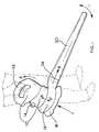
- Fig. 2 shows a blowervac according to the invention in the vacuuming mode of operation with a dirty fan; and
- Fig. 3 is a close-up view of the end of the vacuum tube shown in Fig. 2.
-
- Referring firstly to Fig. 1, there is shown a blowervac according to the invention in use in the blowing mode of operation, in which dashed lines represent the lower body portion of a user. As shown in Fig. 1, hand-
holdable unit 10, which comprises a motor, has ahandle 12 for grasping by the user and is also provided with apower inlet 14 for attachment of a cable to supply electrical power to the motor. In this mode of operation, the motor is oriented in a generally vertical direction and the output shaft of the motor extends downwardly of hand-holdable unit 10 into the interior ofvolute 16, which encloses an impeller connected to the output shaft (not shown in the drawings). In this orientation, air is drawn intovolute 16 from the atmosphere in the direction indicated by arrow J through an inlet to volute 16 provided on the underside thereof and is expelled through an outlet ofvolute 16 in the direction indicated by arrow K downblower tube 20. As may be seen from Fig. 1,blower tube 20 is coplanar withvolute 16, so that air fromvolute 16 can pass freely downblower tube 20 without encountering any sharp turns.Blower tube 20 is also slightly tapered towards its open end, in order to concentrate the air fromvolute 16 into a jet which is expelled from the open end ofblower tube 20. This jet may be redirected by a user as desired by swinging the blowervac back and forth in a horizontal plane as indicated in Fig. 1 by double-headedarrow L. Volute 16 is detachable from hand-holdable unit 10 by pulling hand-holdable unit 10 andvolute 16 in opposite directions, as indicated by arrows X and X', respectively. This allows hand-holdable unit 10 to be rotated through approximately 90 degrees in the direction indicated by arrow A for use of the blowervac in the vacuuming mode of operation shown in Fig. 2. - In the embodiment shown in Fig. 1,
volute 16 is also provided with abase 18, which givesvolute 16 some clearance on its underside and therefore allows the blowervac to be rested on a horizontal surface in the configuration shown in Fig. 1, without the risk of foreign bodies accidentally enteringvolute 16 through the inlet thereto. To further protect the inlet to volute 16, as well as to protect users from the impeller when it is in operation, the inlet to volute 16 is also covered by a grille, the spacing of which is smaller than to allow the insertion of a human finger according to safety standard UL-1017 of Underwriters' Laboratory Inc.. - Referring next to Fig. 2, it may be seen that hand-
holdable unit 10 is now attached to adifferent volute 22 having ahandle 24. As shown in Fig. 2, this allows the blowervac to be held in two hands, where dashed lines again represent the lower body portion of a user. In this mode of operation, the motor is oriented in a more horizontal direction than that shown in Fig. 1 and the output shaft of the motor extends from hand-holdable unit 10 into the interior ofvolute 22. Likevolute 16,volute 22 encloses the impeller connected to the output shaft of the motor. In this orientation, air and garden waste are drawn upvacuum tube 26 intovolute 22 in the direction indicated by arrow M, where the garden waste collides with and is mulched by the impeller, before being ejected throughoutlet 28 ofvolute 22 in the direction indicated byarrow N. Volute 22 has a larger interior volume thanvolute 16 in order to accommodate garden waste with a reduced chance of clogging and is detachable from hand-holdable unit 10 by pulling hand-holdable unit 10 andvolute 22 in opposite directions, as indicated in Fig. 2 by arrows Y and Y', respectively. This allows easy access to both the impeller and the interior ofvolute 22 for cleaning purposes in case they become clogged with garden waste. On the other hand, hand-holdable unit 10 comprises an interlock mechanism which prevents operation of the motor when neithervolute 16 norvolute 22 is engaged with hand-holdable unit 10. Thus the impeller cannot be operated when it is exposed. - In the embodiment shown in Fig. 2,
outlet 28 ofvolute 22 feeds directly into anylon bag 30, which provides an air-porous receptacle for collecting garden waste once it has been mulched by the impeller.Bag 30 is further provided with ahandle 32, allowingbag 30 to be removed fromoutlet 28, emptied and reattached, as required. Although not shown in Fig. 2, the interior ofoutlet 28 comprises a tube which extends into the interior ofbag 30. The inner surface of this tube is provided with several rigid vanes aligned with the longitudinal axis of the tube. These form an obstruction allowing the passage of mulched garden waste therethrough, whilst also preventing a user from inserting a finger intovolute 22 sufficiently far to contact the impeller, again as tested in accordance with safety standard UL-1017. - As shown in Figs. 1 and 2, in this embodiment,
blower tube 20 can be separated fromvolute 16 at the join indicated byreference numeral 34 andvacuum tube 26 can be separated fromvolute 22 at the join indicated byreference numeral 36. This allows the blowervac to be disassembled and stored without taking up a large amount of space.Join 36 is located sufficiently far fromvolute 22 to make it impossible for a user to insert a finger intovolute 22 through the inlet thereof when the impeller is running, as tested according to safety standard UL-1017. On the other hand, since join 34 is located closer to volute 16 than join 36 is to volute 22, the outlet ofvolute 16 is provided with vanes on its inner surface similar to those provided on the interior of the tube insideoutlet 28 ofvolute 22. These vanes therefore prevent a user from inserting a finger intovolute 16 through the outlet thereof when the impeller is running, again as tested in accordance with safety standard UL-1017. - Finally referring to Fig. 3, there is shown a close-up view of the end of
vacuum tube 26 remote fromvolute 22. As may be seen in Fig. 3, this end comprises ascraper 34 integrally moulded withvacuum tube 26.Scraper 34 is substantially flat and is oriented relative to the longitudinal axis ofvacuum tube 26 at such an angle that whenvacuum tube 26 is held as shown in Fig. 2,scraper 34 is parallel with the ground. This angle is preferably in the range of from 30 to 60 degrees. Thus ifscraper 34 is brought into contact with the ground whenvacuum tube 26 is held at this angle, leadingedge 36 ofscraper 34 helps to pick up garden waste and to direct it up theopen end 38 ofvacuum tube 26. This is particularly helpful in the collection of wet garden waste, which otherwise can be difficult to pick up with ablowervac by suction alone.
Claims (13)
- A blower-vacuum device with both a blowing mode of operation and a vacuuming mode of operation and having dirty fan operation in the vacuuming mode thereof, comprising:characterized in that:a hand-holdable unit (10) comprising a motor having an output shaft extending outwardly of said hand-holdable unit;an impeller connected to said output shaft;a first attachment (22, 24, 26, 28) for removable engagement with the hand-holdable unit (10) in the vacuuming mode of operation and comprising both a first volute (22) for enclosing said impeller and a vacuum tube (26) in fluid communication with an inlet of said first volute;a second attachment (16, 18, 20) for removable engagement with the hand-holdable unit (10) in the blowing mode of operation and comprising both a second volute (16) for enclosing said impeller and a blower tube (20) in fluid communication with an outlet of said second volute;the first attachment further comprises a handle (24) on or proximal to said first volute (22); andthe blower tube (20) of the second attachment is coplanar with the second volute (16).
- A blower-vacuum device according to claim 1, wherein the second volute (16) has a smaller interior volume than the first volute (22).
- A blower-vacuum device according to claim 1 or claim 2, wherein the first attachment is separable into a first portion comprising the first volute (22) and a second portion comprising at least a part of the vacuum tube (26).
- A blower-vacuum device according to any one of the preceding claims, wherein the second attachment is separable into a first portion comprising the second volute (16) and a second portion comprising at least a part of the blower tube (20).
- A blower-vacuum device according to any one of the preceding claims, wherein the hand-holdable unit (10) comprises an interlock mechanism for preventing operation of the motor when neither the first attachment nor the second attachment is engaged therewith.
- A blower-vacuum device according to any one of the preceding claims, wherein the first attachment comprises means (34) for scraping garden waste from the ground located at the end of the vacuum tube (26) remote from the first volute (22).
- A blower-vacuum device according to claim 6, wherein the means for scraping garden waste from the ground comprises a scraper (34) oriented relative to the longitudinal axis of the vacuum tube (26) at an angle of from 30 to 60 degrees.
- A blower-vacuum device according to any one of the preceding claims, wherein an outlet (28) of the first volute (22) comprises an obstruction for allowing passage of mulched garden waste therethrough, but preventing insertion of a human finger into the first volute sufficiently far to contact the impeller, as tested in accordance with safety standard UL-1017 of Underwriters' Laboratory Inc.
- A blower-vacuum device according to claim 8, wherein the outlet (28) of the first volute (22) comprises a tube and the obstruction comprises one or more vanes on the inner surface of said tube aligned with the longitudinal axis thereof.
- A blower-vacuum device according to any one of the preceding claims, wherein an outlet of the second volute (16) comprises an obstruction for allowing passage of air therethrough, but preventing insertion of a human finger into the second volute sufficiently far to contact the impeller, as tested in accordance with safety standard UL-1017 of Underwriters' Laboratory Inc.
- A blower-vacuum device according to claim 10, wherein the outlet of the second volute (16) comprises a tube and the obstruction comprises one or more vanes on the inner surface of said tube aligned with the longitudinal axis thereof.
- A blower-vacuum device according to any one of the preceding claims, further comprising an air-porous receptacle (30, 32) for removable attachment to the outlet of the first volute.
- A blower-vacuum device substantially as hereinbefore described with reference to the accompanying drawings.
Applications Claiming Priority (2)
| Application Number | Priority Date | Filing Date | Title |
|---|---|---|---|
| GB0229517 | 2002-12-19 | ||
| GB0229517A GB2396292A (en) | 2002-12-19 | 2002-12-19 | Blower-vacuum devices |
Publications (3)
| Publication Number | Publication Date |
|---|---|
| EP1430825A2 true EP1430825A2 (en) | 2004-06-23 |
| EP1430825A3 EP1430825A3 (en) | 2005-06-15 |
| EP1430825B1 EP1430825B1 (en) | 2007-04-11 |
Family
ID=9949928
Family Applications (1)
| Application Number | Title | Priority Date | Filing Date |
|---|---|---|---|
| EP03028097A Expired - Lifetime EP1430825B1 (en) | 2002-12-19 | 2003-12-09 | Blower-vacuum device |
Country Status (8)
| Country | Link |
|---|---|
| US (1) | US7266860B2 (en) |
| EP (1) | EP1430825B1 (en) |
| AT (1) | ATE359017T1 (en) |
| AU (1) | AU2003270942B2 (en) |
| CA (1) | CA2453731C (en) |
| DE (1) | DE60313109T2 (en) |
| ES (1) | ES2283704T3 (en) |
| GB (1) | GB2396292A (en) |
Cited By (1)
| Publication number | Priority date | Publication date | Assignee | Title |
|---|---|---|---|---|
| CN103004484A (en) * | 2012-12-14 | 2013-04-03 | 常州光辉化工有限公司 | Blow-suction tool |
Families Citing this family (6)
| Publication number | Priority date | Publication date | Assignee | Title |
|---|---|---|---|---|
| CN101322626B (en) * | 2007-06-14 | 2011-12-07 | 苏州宝时得电动工具有限公司 | Pressure-vaccum machine |
| US8806705B2 (en) * | 2009-04-10 | 2014-08-19 | John M. Minor | Leaf blower |
| US8434589B1 (en) | 2011-11-14 | 2013-05-07 | Xerox Corporation | Obstruction device for reducing noise emitted from a blower |
| US8862017B2 (en) | 2012-01-25 | 2014-10-14 | Xerox Corporation | Use of an acoustic cavity to reduce acoustic noise from a centrifugal blower |
| CN106284149B (en) * | 2015-05-11 | 2018-05-11 | 南京德朔实业有限公司 | Hair-dryer |
| EP3225740B1 (en) * | 2014-11-28 | 2021-11-10 | Positec Power Tools (Suzhou) Co., Ltd | Blower/vacuum apparatus |
Citations (4)
| Publication number | Priority date | Publication date | Assignee | Title |
|---|---|---|---|---|
| EP0723758A2 (en) * | 1995-01-30 | 1996-07-31 | Black & Decker Inc. | Debris blower and/or vacuum devices |
| GB2311462A (en) * | 1996-03-28 | 1997-10-01 | Black & Decker Inc | Blower vacuum |
| US5991973A (en) * | 1997-08-15 | 1999-11-30 | Simpson; Timothy A. | Air yard blower |
| US6073305A (en) * | 1998-03-02 | 2000-06-13 | Hesskamp; Scott | Debris blower |
Family Cites Families (5)
| Publication number | Priority date | Publication date | Assignee | Title |
|---|---|---|---|---|
| US4694528A (en) * | 1986-07-18 | 1987-09-22 | The Toro Company | Convertible vacuum-blower |
| US4870714A (en) * | 1987-11-09 | 1989-10-03 | Black & Decker Inc. | Portable blower/vacuum system |
| US5535479A (en) * | 1995-01-19 | 1996-07-16 | The Toro Company | Portable blower/vacuum handle arrangement |
| EP0723759B1 (en) * | 1995-01-30 | 2002-07-10 | Black & Decker Inc. | A blower-vacuum device |
| GB2299749B (en) * | 1995-03-11 | 1998-09-02 | Black & Decker Inc | A blower vacuum device of improved design |
-
2002
- 2002-12-19 GB GB0229517A patent/GB2396292A/en not_active Withdrawn
-
2003
- 2003-12-09 AT AT03028097T patent/ATE359017T1/en not_active IP Right Cessation
- 2003-12-09 ES ES03028097T patent/ES2283704T3/en not_active Expired - Lifetime
- 2003-12-09 EP EP03028097A patent/EP1430825B1/en not_active Expired - Lifetime
- 2003-12-09 DE DE60313109T patent/DE60313109T2/en not_active Expired - Lifetime
- 2003-12-17 AU AU2003270942A patent/AU2003270942B2/en not_active Ceased
- 2003-12-19 CA CA002453731A patent/CA2453731C/en not_active Expired - Fee Related
- 2003-12-22 US US10/742,287 patent/US7266860B2/en not_active Expired - Fee Related
Patent Citations (4)
| Publication number | Priority date | Publication date | Assignee | Title |
|---|---|---|---|---|
| EP0723758A2 (en) * | 1995-01-30 | 1996-07-31 | Black & Decker Inc. | Debris blower and/or vacuum devices |
| GB2311462A (en) * | 1996-03-28 | 1997-10-01 | Black & Decker Inc | Blower vacuum |
| US5991973A (en) * | 1997-08-15 | 1999-11-30 | Simpson; Timothy A. | Air yard blower |
| US6073305A (en) * | 1998-03-02 | 2000-06-13 | Hesskamp; Scott | Debris blower |
Cited By (1)
| Publication number | Priority date | Publication date | Assignee | Title |
|---|---|---|---|---|
| CN103004484A (en) * | 2012-12-14 | 2013-04-03 | 常州光辉化工有限公司 | Blow-suction tool |
Also Published As
| Publication number | Publication date |
|---|---|
| EP1430825B1 (en) | 2007-04-11 |
| US7266860B2 (en) | 2007-09-11 |
| EP1430825A3 (en) | 2005-06-15 |
| CA2453731A1 (en) | 2004-06-19 |
| DE60313109T2 (en) | 2008-01-03 |
| ES2283704T3 (en) | 2007-11-01 |
| GB2396292A (en) | 2004-06-23 |
| GB0229517D0 (en) | 2003-01-22 |
| DE60313109D1 (en) | 2007-05-24 |
| ATE359017T1 (en) | 2007-05-15 |
| US20040187252A1 (en) | 2004-09-30 |
| CA2453731C (en) | 2009-02-24 |
| AU2003270942A1 (en) | 2004-07-08 |
| AU2003270942B2 (en) | 2008-10-09 |
Similar Documents
| Publication | Publication Date | Title |
|---|---|---|
| EP2617281B1 (en) | Apparatus for collection of garden waste | |
| EP0723758B1 (en) | Debris blower and/or vacuum devices | |
| EP0198654B1 (en) | Blower/vacuum device | |
| KR100654393B1 (en) | Vacuum cleaner | |
| CA2484587A1 (en) | Hand-held cordless vacuum cleaner | |
| US5659920A (en) | Blower vacuum device of improved design | |
| US20220257071A1 (en) | Wet-dry vacuum cleaner device | |
| US20090000055A1 (en) | Means for collecting garden waste | |
| EP1430825B1 (en) | Blower-vacuum device | |
| US20080022481A1 (en) | Leaf removal system | |
| US4469498A (en) | Dirt interceptor filter bag mount for vacuum cleaner | |
| EP0684341A1 (en) | Collection apparatus | |
| EP0792578A2 (en) | Portable blower-vacuum unit | |
| US11873611B2 (en) | Collection device for debris and animal waste | |
| EP0511766A2 (en) | Lawn mower | |
| CN216167166U (en) | Electric floor sweeper | |
| US20140130327A1 (en) | Wet/Dry Vacuum Cleaner Leaf Mulcher | |
| US20190343348A1 (en) | Bucket lid attachment apparatus for handheld vacuum and blower devices | |
| EP0821867A1 (en) | Lawnmower with grass collector | |
| KR200229266Y1 (en) | Vacuum cleaner | |
| AU1019500A (en) | An apparatus for picking up and collecting particulate material |
Legal Events
| Date | Code | Title | Description |
|---|---|---|---|
| PUAI | Public reference made under article 153(3) epc to a published international application that has entered the european phase |
Free format text: ORIGINAL CODE: 0009012 |
|
| AK | Designated contracting states |
Kind code of ref document: A2 Designated state(s): AT BE BG CH CY CZ DE DK EE ES FI FR GB GR HU IE IT LI LU MC NL PT RO SE SI SK TR |
|
| AX | Request for extension of the european patent |
Extension state: AL LT LV MK |
|
| PUAL | Search report despatched |
Free format text: ORIGINAL CODE: 0009013 |
|
| AK | Designated contracting states |
Kind code of ref document: A3 Designated state(s): AT BE BG CH CY CZ DE DK EE ES FI FR GB GR HU IE IT LI LU MC NL PT RO SE SI SK TR |
|
| AX | Request for extension of the european patent |
Extension state: AL LT LV MK |
|
| RIC1 | Information provided on ipc code assigned before grant |
Ipc: 7A 47L 5/14 A Ipc: 7A 47L 9/28 B Ipc: 7E 01H 1/08 B Ipc: 7A 01G 1/12 B |
|
| 17P | Request for examination filed |
Effective date: 20050623 |
|
| AKX | Designation fees paid |
Designated state(s): AT BE BG CH CY CZ DE DK EE ES FI FR GB GR HU IE IT LI LU MC NL PT RO SE SI SK TR |
|
| GRAP | Despatch of communication of intention to grant a patent |
Free format text: ORIGINAL CODE: EPIDOSNIGR1 |
|
| GRAS | Grant fee paid |
Free format text: ORIGINAL CODE: EPIDOSNIGR3 |
|
| GRAA | (expected) grant |
Free format text: ORIGINAL CODE: 0009210 |
|
| AK | Designated contracting states |
Kind code of ref document: B1 Designated state(s): AT BE BG CH CY CZ DE DK EE ES FI FR GB GR HU IE IT LI LU MC NL PT RO SE SI SK TR |
|
| PG25 | Lapsed in a contracting state [announced via postgrant information from national office to epo] |
Ref country code: FI Free format text: LAPSE BECAUSE OF FAILURE TO SUBMIT A TRANSLATION OF THE DESCRIPTION OR TO PAY THE FEE WITHIN THE PRESCRIBED TIME-LIMIT Effective date: 20070411 Ref country code: SI Free format text: LAPSE BECAUSE OF FAILURE TO SUBMIT A TRANSLATION OF THE DESCRIPTION OR TO PAY THE FEE WITHIN THE PRESCRIBED TIME-LIMIT Effective date: 20070411 |
|
| REG | Reference to a national code |
Ref country code: GB Ref legal event code: FG4D |
|
| REG | Reference to a national code |
Ref country code: CH Ref legal event code: EP |
|
| REG | Reference to a national code |
Ref country code: IE Ref legal event code: FG4D |
|
| REF | Corresponds to: |
Ref document number: 60313109 Country of ref document: DE Date of ref document: 20070524 Kind code of ref document: P |
|
| REG | Reference to a national code |
Ref country code: SE Ref legal event code: TRGR |
|
| REG | Reference to a national code |
Ref country code: CH Ref legal event code: NV Representative=s name: E. BLUM & CO. AG PATENT- UND MARKENANWAELTE VSP |
|
| PG25 | Lapsed in a contracting state [announced via postgrant information from national office to epo] |
Ref country code: PT Free format text: LAPSE BECAUSE OF FAILURE TO SUBMIT A TRANSLATION OF THE DESCRIPTION OR TO PAY THE FEE WITHIN THE PRESCRIBED TIME-LIMIT Effective date: 20070911 |
|
| ET | Fr: translation filed | ||
| REG | Reference to a national code |
Ref country code: ES Ref legal event code: FG2A Ref document number: 2283704 Country of ref document: ES Kind code of ref document: T3 |
|
| PG25 | Lapsed in a contracting state [announced via postgrant information from national office to epo] |
Ref country code: CZ Free format text: LAPSE BECAUSE OF FAILURE TO SUBMIT A TRANSLATION OF THE DESCRIPTION OR TO PAY THE FEE WITHIN THE PRESCRIBED TIME-LIMIT Effective date: 20070411 Ref country code: DK Free format text: LAPSE BECAUSE OF FAILURE TO SUBMIT A TRANSLATION OF THE DESCRIPTION OR TO PAY THE FEE WITHIN THE PRESCRIBED TIME-LIMIT Effective date: 20070411 Ref country code: BG Free format text: LAPSE BECAUSE OF FAILURE TO SUBMIT A TRANSLATION OF THE DESCRIPTION OR TO PAY THE FEE WITHIN THE PRESCRIBED TIME-LIMIT Effective date: 20070711 |
|
| PLBE | No opposition filed within time limit |
Free format text: ORIGINAL CODE: 0009261 |
|
| STAA | Information on the status of an ep patent application or granted ep patent |
Free format text: STATUS: NO OPPOSITION FILED WITHIN TIME LIMIT |
|
| PG25 | Lapsed in a contracting state [announced via postgrant information from national office to epo] |
Ref country code: SK Free format text: LAPSE BECAUSE OF FAILURE TO SUBMIT A TRANSLATION OF THE DESCRIPTION OR TO PAY THE FEE WITHIN THE PRESCRIBED TIME-LIMIT Effective date: 20070411 |
|
| 26N | No opposition filed |
Effective date: 20080114 |
|
| PG25 | Lapsed in a contracting state [announced via postgrant information from national office to epo] |
Ref country code: GR Free format text: LAPSE BECAUSE OF FAILURE TO SUBMIT A TRANSLATION OF THE DESCRIPTION OR TO PAY THE FEE WITHIN THE PRESCRIBED TIME-LIMIT Effective date: 20070712 |
|
| PG25 | Lapsed in a contracting state [announced via postgrant information from national office to epo] |
Ref country code: RO Free format text: LAPSE BECAUSE OF FAILURE TO SUBMIT A TRANSLATION OF THE DESCRIPTION OR TO PAY THE FEE WITHIN THE PRESCRIBED TIME-LIMIT Effective date: 20070411 |
|
| PG25 | Lapsed in a contracting state [announced via postgrant information from national office to epo] |
Ref country code: MC Free format text: LAPSE BECAUSE OF NON-PAYMENT OF DUE FEES Effective date: 20071231 |
|
| PG25 | Lapsed in a contracting state [announced via postgrant information from national office to epo] |
Ref country code: EE Free format text: LAPSE BECAUSE OF FAILURE TO SUBMIT A TRANSLATION OF THE DESCRIPTION OR TO PAY THE FEE WITHIN THE PRESCRIBED TIME-LIMIT Effective date: 20070411 |
|
| PGFP | Annual fee paid to national office [announced via postgrant information from national office to epo] |
Ref country code: CH Payment date: 20081229 Year of fee payment: 6 Ref country code: IE Payment date: 20081224 Year of fee payment: 6 |
|
| PGFP | Annual fee paid to national office [announced via postgrant information from national office to epo] |
Ref country code: AT Payment date: 20081119 Year of fee payment: 6 Ref country code: ES Payment date: 20081226 Year of fee payment: 6 |
|
| PGFP | Annual fee paid to national office [announced via postgrant information from national office to epo] |
Ref country code: IT Payment date: 20081222 Year of fee payment: 6 |
|
| PG25 | Lapsed in a contracting state [announced via postgrant information from national office to epo] |
Ref country code: CY Free format text: LAPSE BECAUSE OF FAILURE TO SUBMIT A TRANSLATION OF THE DESCRIPTION OR TO PAY THE FEE WITHIN THE PRESCRIBED TIME-LIMIT Effective date: 20070411 |
|
| PGFP | Annual fee paid to national office [announced via postgrant information from national office to epo] |
Ref country code: BE Payment date: 20090202 Year of fee payment: 6 |
|
| PG25 | Lapsed in a contracting state [announced via postgrant information from national office to epo] |
Ref country code: LU Free format text: LAPSE BECAUSE OF NON-PAYMENT OF DUE FEES Effective date: 20071209 |
|
| PG25 | Lapsed in a contracting state [announced via postgrant information from national office to epo] |
Ref country code: TR Free format text: LAPSE BECAUSE OF FAILURE TO SUBMIT A TRANSLATION OF THE DESCRIPTION OR TO PAY THE FEE WITHIN THE PRESCRIBED TIME-LIMIT Effective date: 20070411 Ref country code: HU Free format text: LAPSE BECAUSE OF FAILURE TO SUBMIT A TRANSLATION OF THE DESCRIPTION OR TO PAY THE FEE WITHIN THE PRESCRIBED TIME-LIMIT Effective date: 20071012 |
|
| BERE | Be: lapsed |
Owner name: BLACK & DECKER INC. Effective date: 20091231 |
|
| REG | Reference to a national code |
Ref country code: CH Ref legal event code: PL |
|
| PG25 | Lapsed in a contracting state [announced via postgrant information from national office to epo] |
Ref country code: AT Free format text: LAPSE BECAUSE OF NON-PAYMENT OF DUE FEES Effective date: 20091209 |
|
| PG25 | Lapsed in a contracting state [announced via postgrant information from national office to epo] |
Ref country code: CH Free format text: LAPSE BECAUSE OF NON-PAYMENT OF DUE FEES Effective date: 20091231 Ref country code: BE Free format text: LAPSE BECAUSE OF NON-PAYMENT OF DUE FEES Effective date: 20091231 Ref country code: IE Free format text: LAPSE BECAUSE OF NON-PAYMENT OF DUE FEES Effective date: 20091209 Ref country code: LI Free format text: LAPSE BECAUSE OF NON-PAYMENT OF DUE FEES Effective date: 20091231 |
|
| REG | Reference to a national code |
Ref country code: ES Ref legal event code: FD2A Effective date: 20110310 |
|
| PG25 | Lapsed in a contracting state [announced via postgrant information from national office to epo] |
Ref country code: IT Free format text: LAPSE BECAUSE OF NON-PAYMENT OF DUE FEES Effective date: 20091209 |
|
| PG25 | Lapsed in a contracting state [announced via postgrant information from national office to epo] |
Ref country code: ES Free format text: LAPSE BECAUSE OF NON-PAYMENT OF DUE FEES Effective date: 20110309 |
|
| PG25 | Lapsed in a contracting state [announced via postgrant information from national office to epo] |
Ref country code: ES Free format text: LAPSE BECAUSE OF NON-PAYMENT OF DUE FEES Effective date: 20091210 |
|
| REG | Reference to a national code |
Ref country code: FR Ref legal event code: PLFP Year of fee payment: 13 |
|
| REG | Reference to a national code |
Ref country code: FR Ref legal event code: PLFP Year of fee payment: 14 |
|
| REG | Reference to a national code |
Ref country code: FR Ref legal event code: PLFP Year of fee payment: 15 |
|
| PGFP | Annual fee paid to national office [announced via postgrant information from national office to epo] |
Ref country code: DE Payment date: 20171206 Year of fee payment: 15 Ref country code: NL Payment date: 20171213 Year of fee payment: 15 Ref country code: FR Payment date: 20171113 Year of fee payment: 15 |
|
| PGFP | Annual fee paid to national office [announced via postgrant information from national office to epo] |
Ref country code: SE Payment date: 20171213 Year of fee payment: 15 Ref country code: GB Payment date: 20171206 Year of fee payment: 15 |
|
| REG | Reference to a national code |
Ref country code: DE Ref legal event code: R119 Ref document number: 60313109 Country of ref document: DE |
|
| REG | Reference to a national code |
Ref country code: SE Ref legal event code: EUG |
|
| PG25 | Lapsed in a contracting state [announced via postgrant information from national office to epo] |
Ref country code: SE Free format text: LAPSE BECAUSE OF NON-PAYMENT OF DUE FEES Effective date: 20181210 |
|
| REG | Reference to a national code |
Ref country code: NL Ref legal event code: MM Effective date: 20190101 |
|
| GBPC | Gb: european patent ceased through non-payment of renewal fee |
Effective date: 20181209 |
|
| PG25 | Lapsed in a contracting state [announced via postgrant information from national office to epo] |
Ref country code: NL Free format text: LAPSE BECAUSE OF NON-PAYMENT OF DUE FEES Effective date: 20190101 |
|
| PG25 | Lapsed in a contracting state [announced via postgrant information from national office to epo] |
Ref country code: DE Free format text: LAPSE BECAUSE OF NON-PAYMENT OF DUE FEES Effective date: 20190702 Ref country code: FR Free format text: LAPSE BECAUSE OF NON-PAYMENT OF DUE FEES Effective date: 20181231 |
|
| PG25 | Lapsed in a contracting state [announced via postgrant information from national office to epo] |
Ref country code: GB Free format text: LAPSE BECAUSE OF NON-PAYMENT OF DUE FEES Effective date: 20181209 |