EP1429588A2 - X-ray controlling method and x-ray imaging apparatus - Google Patents
X-ray controlling method and x-ray imaging apparatus Download PDFInfo
- Publication number
- EP1429588A2 EP1429588A2 EP03257441A EP03257441A EP1429588A2 EP 1429588 A2 EP1429588 A2 EP 1429588A2 EP 03257441 A EP03257441 A EP 03257441A EP 03257441 A EP03257441 A EP 03257441A EP 1429588 A2 EP1429588 A2 EP 1429588A2
- Authority
- EP
- European Patent Office
- Prior art keywords
- ray
- exposure dose
- imaging
- subject
- tube current
- Prior art date
- Legal status (The legal status is an assumption and is not a legal conclusion. Google has not performed a legal analysis and makes no representation as to the accuracy of the status listed.)
- Withdrawn
Links
- 238000003384 imaging method Methods 0.000 title claims abstract description 96
- 238000000034 method Methods 0.000 title claims abstract description 23
- 230000009467 reduction Effects 0.000 abstract description 4
- 238000012545 processing Methods 0.000 description 22
- 238000002591 computed tomography Methods 0.000 description 15
- 230000001276 controlling effect Effects 0.000 description 12
- 238000010586 diagram Methods 0.000 description 8
- 238000004364 calculation method Methods 0.000 description 7
- 238000004891 communication Methods 0.000 description 6
- 238000012986 modification Methods 0.000 description 6
- 230000004048 modification Effects 0.000 description 6
- 238000013480 data collection Methods 0.000 description 5
- 231100000628 reference dose Toxicity 0.000 description 4
- 230000004807 localization Effects 0.000 description 3
- MARUHZGHZWCEQU-UHFFFAOYSA-N 5-phenyl-2h-tetrazole Chemical compound C1=CC=CC=C1C1=NNN=N1 MARUHZGHZWCEQU-UHFFFAOYSA-N 0.000 description 2
- 238000005259 measurement Methods 0.000 description 2
- 230000008859 change Effects 0.000 description 1
- 230000000694 effects Effects 0.000 description 1
- 125000001153 fluoro group Chemical group F* 0.000 description 1
- 230000006870 function Effects 0.000 description 1
- 230000001105 regulatory effect Effects 0.000 description 1
- 239000004065 semiconductor Substances 0.000 description 1
- 229910052724 xenon Inorganic materials 0.000 description 1
- FHNFHKCVQCLJFQ-UHFFFAOYSA-N xenon atom Chemical compound [Xe] FHNFHKCVQCLJFQ-UHFFFAOYSA-N 0.000 description 1
Images




Classifications
-
- A—HUMAN NECESSITIES
- A61—MEDICAL OR VETERINARY SCIENCE; HYGIENE
- A61B—DIAGNOSIS; SURGERY; IDENTIFICATION
- A61B6/00—Apparatus or devices for radiation diagnosis; Apparatus or devices for radiation diagnosis combined with radiation therapy equipment
- A61B6/10—Safety means specially adapted therefor
-
- H—ELECTRICITY
- H05—ELECTRIC TECHNIQUES NOT OTHERWISE PROVIDED FOR
- H05G—X-RAY TECHNIQUE
- H05G1/00—X-ray apparatus involving X-ray tubes; Circuits therefor
- H05G1/08—Electrical details
- H05G1/26—Measuring, controlling or protecting
- H05G1/30—Controlling
- H05G1/34—Anode current, heater current or heater voltage of X-ray tube
-
- A—HUMAN NECESSITIES
- A61—MEDICAL OR VETERINARY SCIENCE; HYGIENE
- A61B—DIAGNOSIS; SURGERY; IDENTIFICATION
- A61B6/00—Apparatus or devices for radiation diagnosis; Apparatus or devices for radiation diagnosis combined with radiation therapy equipment
- A61B6/02—Arrangements for diagnosis sequentially in different planes; Stereoscopic radiation diagnosis
- A61B6/03—Computed tomography [CT]
- A61B6/032—Transmission computed tomography [CT]
-
- A—HUMAN NECESSITIES
- A61—MEDICAL OR VETERINARY SCIENCE; HYGIENE
- A61B—DIAGNOSIS; SURGERY; IDENTIFICATION
- A61B6/00—Apparatus or devices for radiation diagnosis; Apparatus or devices for radiation diagnosis combined with radiation therapy equipment
- A61B6/48—Diagnostic techniques
- A61B6/488—Diagnostic techniques involving pre-scan acquisition
-
- A—HUMAN NECESSITIES
- A61—MEDICAL OR VETERINARY SCIENCE; HYGIENE
- A61B—DIAGNOSIS; SURGERY; IDENTIFICATION
- A61B6/00—Apparatus or devices for radiation diagnosis; Apparatus or devices for radiation diagnosis combined with radiation therapy equipment
- A61B6/54—Control of apparatus or devices for radiation diagnosis
- A61B6/542—Control of apparatus or devices for radiation diagnosis involving control of exposure
-
- H—ELECTRICITY
- H05—ELECTRIC TECHNIQUES NOT OTHERWISE PROVIDED FOR
- H05G—X-RAY TECHNIQUE
- H05G1/00—X-ray apparatus involving X-ray tubes; Circuits therefor
- H05G1/08—Electrical details
- H05G1/26—Measuring, controlling or protecting
- H05G1/28—Measuring or recording actual exposure time; Counting number of exposures; Measuring required exposure time
Definitions
- the present invention relates to an X-ray controlling method and an X-ray imaging apparatus, and more particularly to a method of controlling the tube current of an X-ray tube, and an X-ray imaging apparatus for conducting imaging while controlling the tube current of an X-ray tube.
- the tube current of an X-ray tube is set before starting imaging as described in Japanese Patent Application Laid Open No. 2001-43993.
- the setting of the tube current in the above manner primarily stresses image quality in imaging, and does not necessarily stress reduction of exposure dose.
- the present invention in accordance with one aspect for solving the aforementioned problem, is an X-ray controlling method for an X-ray imaging apparatus for projecting X-rays from an X-ray tube onto a subject to be imaged and detecting transmitted X-rays, and producing an image based on detected X-ray signals, said method characterized in comprising: setting an upper limit of an X-ray exposure dose to the subject to be imaged; and modulating the tube current of the X-ray tube so that the exposure dose does not exceed the upper limit.
- the present invention in accordance with another aspect for solving the aforementioned problem, is an X-ray imaging apparatus for projecting X-rays from an X-ray tube onto a subject to be imaged and detecting transmitted X-rays, and producing an image based on detected X-ray signals, said apparatus characterized in comprising: setting means for setting an upper limit of an X-ray exposure dose to the subject to be imaged; and modulating means for modulating the tube current of the X-ray tube so that the exposure dose does not exceed the upper limit.
- an upper limit of an X-ray exposure dose is set for a subject to be imaged, and the tube current of the X-ray tube is modulated so that the exposure dose does not exceed the upper limit; and therefore, the exposure dose to the subject to be imaged is reduced.
- the X-ray imaging apparatus is an X-ray CT apparatus so that a tomographic image may be captured at a low exposure dose.
- the X-ray CT apparatus conducts imaging by a helical scan so that a tomographic image over a wide range may be captured at a low exposure dose.
- the modulation of the tube current is achieved by: finding an exposure dose predicted value based on an imaging protocol; and modifying the tube current set value in the imaging protocol when the predicted value exceeds the upper limit, so that the tomographic imaging at a low exposure dose may be suitably conducted.
- the tube current set value is specified for each slice position so that the quality of tomographic images may be kept constant regardless of the slice position.
- the present invention in accordance with still another aspect for solving the aforementioned problem, is an X-ray imaging apparatus for projecting X-rays from an X-ray tube onto a subject to be imaged and detecting transmitted X-rays, and producing an image based on detected X-ray signals, said apparatus characterized in comprising: calculating means for calculating a historical X-ray exposure dose to the subject to be imaged; and display means for displaying the calculated exposure dose.
- the calculating means calculates the exposure dose based on historical imaging data for the subject to be imaged so that the exposure dose may be correctly calculated.
- the calculating means acquires the historical imaging data from a server so that data acquisition may be facilitated.
- the X-ray imaging apparatus is an X-ray CT apparatus so that the exposure dose during tomographic imaging may be reduced.
- the present invention provides an X-ray controlling method that enables reduction of exposure dose, and an X-ray imaging apparatus that conducts X-ray control by such method.
- Figure 1 shows a block diagram of an X-ray CT apparatus, which is an embodiment of the present invention.
- the configuration of the apparatus represents an embodiment of the apparatus in accordance with the present invention.
- the operation of the apparatus represents an embodiment of the method in accordance with the present invention.
- the apparatus comprises a scan gantry 2, an imaging table 4 and an operating console 6.
- the scan gantry 2 has an X-ray tube 20.
- X-rays (not shown) emitted from the X-ray tube 20 are formed into a fan-shaped X-ray beam, i.e., a fan beam, by a collimator 22, and projected toward an X-ray detector 24.
- the X-ray detector 24 has a plurality of detector elements arranged in line as an array in the extent direction of the fan-shaped X-ray beam. The configuration of the X-ray detector 24 will be described in detail later.
- the X-ray tube 20, collimator 22 and X-ray detector 24 together constitute an X-ray emitting/detecting apparatus, which will be described in detail later.
- the X-ray detector 24 is connected with a data collecting section 26.
- the data collecting section 26 collects signals detected by the individual detector elements in the X-ray detector 24 as digital data.
- the emission of the X-rays from the X-ray tube 20 is controlled by an X-ray controller 28.
- the interconnection between the X-ray tube 20 and X-ray controller 28 is omitted in the drawing.
- the collimator 22 is controlled by a collimator controller 30.
- the interconnection between the collimator 22 and collimator controller 30 is omitted in the drawing.
- the above-described components from the X-ray tube 20 through the collimator controller 30 are mounted on a rotating section 34 of the scan gantry 2.
- the rotation of the rotating section 34 is controlled by a rotation controller 36.
- the interconnection between the rotating section 34 and rotation controller 36 is omitted in the drawing.
- the imaging table 4 is configured to carry a subject to be imaged (not shown) into and out of an X-ray irradiation space in the scan gantry 2. The relationship between the subject and X-ray irradiation space will be described in detail later.
- the operating console 6 has a data processing apparatus 60.
- the data processing apparatus 60 is comprised of, for example, a computer.
- the data processing apparatus 60 is connected with a control interface 62.
- the control interface 62 is connected with the scan gantry 2 and the imaging table 4.
- the data processing apparatus 60 controls the scan gantry 2 and imaging table 4 via the control interface 62.
- the data collecting section 26, X-ray controller 28, collimator controller 30 and rotation controller 36 in the scan gantry 2 are controlled via the control interface 62.
- the individual connections between these sections and the control interface 62 are omitted in the drawing.
- the data processing apparatus 60 is also connected with a data collection buffer 64.
- the data collection buffer 64 is connected with the data collecting section 26 in the scan gantry 2. Data collected at the data collecting section 26 are input to the data processing apparatus 60 via the data collection buffer 64.
- the data processing apparatus 60 performs image reconstruction using transmitted X-ray data for a plurality of views collected via the data collection buffer 64.
- the image reconstruction is performed using a filtered backprojection technique, for example.
- the data processing apparatus 60 is also connected with a storage device 66.
- the storage device 66 stores several kinds of data, programs, and so forth. Several kinds of data processing relating to imaging are achieved by the data processing apparatus 60 executing the programs stored in the storage device 66.
- the data processing apparatus 60 is further connected with a display device 68 and an operating device 70.
- the display device 68 displays the reconstructed image and other information output from the data processing apparatus 60.
- the operating device 70 is operated by a user, and supplies several kinds of instructions and information to the data processing apparatus 60. The user interactively operates the present apparatus using the display device 68 and operating device 70.
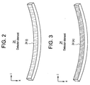
- Figure 2 schematically shows one configuration of the X-ray detector 24.
- this X-ray detector 24 is a multi-channel X-ray detector having a multiplicity of detector elements 24(i) arranged in a one-dimensional array.
- the detector elements 24(i) together form an X-ray impingement surface curved as a cylindrical concavity.
- the X-ray detector 24 may instead be one having a plurality of detector elements 24(ik) arranged in a two-dimensional array, as shown in Figure 3.
- the detector elements 24(ik) together form an X-ray impingement surface curved as a cylindrical concavity.
- the detector elements 24(ik) that have the same row index 'k' together constitute a detector element row.
- the X-ray detector 24 is not limited to having four detector element rows, and may have a plurality of rows that is more or less than four rows.
- Each detector element 24(ik) is formed of a combination of a scintillator and a photodiode, for example. It should be noted that the detector element 24(ik) is not limited thereto but may be a semiconductor detector element using cadmium telluride (CdTe) or the like, or an ionization chamber detector element using xenon (Xe) gas, for example.
- CdTe cadmium telluride
- Xe xenon
- Figure 4 shows an interrelationship among the X-ray tube 20, collimator 22 and X-ray detector 24 in the X-ray emitting/detecting apparatus.
- Figure 4(a) is a view from the front of the scan gantry 2 and (b) is a view from the side thereof.
- the X-rays emitted from the X-ray tube 20 are formed into a fan-shaped X-ray beam 400 by the collimator 22, and projected toward the X-ray detector 24.
- Figure 4(a) illustrates the extent of the fan-shaped X-ray beam 400.
- the extent direction of the X-ray beam 400 coincides with the direction of the linear arrangement of the channels in the X-ray detector 24.
- Figure 4(b) illustrates the thickness of the X-ray beam 400.
- the thickness direction of the X-ray beam 400 coincides with the direction of the side-by-side arrangement of the detector element rows in the X-ray detector 24.
- a subject 8 placed on the imaging table 4 is carried into the X-ray irradiation space with the subject's body axis intersecting the fan surface of such an X-ray beam 400, as exemplarily shown in Figure 5.
- the scan gantry 2 has a cylindrical structure containing therein the X-ray emitting/detecting apparatus.
- the X-ray irradiation space is formed in the internal space of the cylindrical structure of the scan gantry 2.
- An image of the subject 8 sliced by the X-ray beam 400 is projected onto the X-ray detector 24.
- the X-rays passing through the subject 8 are detected by the X-ray detector 24.
- the thickness 'th' of the X-ray beam 400 impinging upon the subject 8 is regulated by the degree of opening of an aperture of the collimator 22.
- the X-ray emitting/detecting apparatus comprised of the X-ray tube 20, collimator 22 and X-ray detector 24 continuously rotates (or scans) around the body axis of the subject 8 while maintaining their interrelationship.
- the imaging table 4 is continuously moved in the body axis direction of the subject 8 as indicated by an arrow 42 simultaneously with the rotation of the X-ray emitting/detecting apparatus, the X-ray emitting/detecting apparatus will rotate relative to the subject 8 along a helical trajectory surrounding the subject 8, thus conducting a scan generally referred to as a helical scan. It will be easily recognized that when a scan is conducted with the imaging table 4 immobilized, a scan at a fixed slice position, i.e., an axial scan, is conducted.
- Projection data for a plurality of (for example, ca. 1,000) views are collected per scan rotation.
- the collection of the projection data is conducted by a system including the X-ray detector 24, data collecting section 26 and data collection buffer 64.
- the data processing section 60 uses the projection data for the four slices to perform image reconstruction.
- dose adjustment for the particular subject 8 is conducted prior to such a scan.
- the dose adjustment is achieved by modulating the tube current-time product, i.e., the so-called milliampere-seconds (mAs), for the X-ray tube.
- the tube current-time product will be sometimes referred to simply as the tube current hereinbelow.
- Tube current adjustment for the particular subject 8 is sometimes referred to as auto-milliampere (auto mA).
- a projection of the subject 8 is measured.
- the measurement of the projection is achieved by fluoro-imaging the subject 8 by the X-ray beam 400 in, for example, a 0° (sagittal) direction and a 90° (lateral) direction, and obtaining respective projections, as conceptually shown in Figure 7.
- fluoro imaging will be sometimes referred to as scout imaging hereinbelow.
- Proj_0deg will be sometimes referred to as a sagittal center value and proj_90deg as a lateral center value hereinbelow.
- the center values are used to calculate an oval ratio when the cross section of the subject 8 is assumed to be elliptical.
- the oval ratio is given by the following equation:
- the numerator and denominator of the oval ratio are set so that the oval ratio has a value no less than one. Therefore, if the sagittal center value is greater than the lateral center value as in the head, the sagittal center value is set at the numerator and the lateral center value is set at the denominator, contrary to the equation above.
- the one of the sagittal and lateral center values that has a larger value corresponds to the major axis of the ellipse, and the other that has a smaller value corresponds to the minor axis.
- the projection area is obtained from either Equation (1) or (2) depending upon the direction of the fluoro-imaging, and the center value of the projection is similarly obtained from either Equation (3) or (4) depending upon the direction of the fluoro-imaging.
- projection_area ( proj_ 0deg ⁇ proj_ 90deg) ⁇ S + I , where
- proj_orthogonal projection_area - I proj_measure ⁇ S , where proj_measure: a center value known by measurement.
- oval_ratio proj_orthogonal proj_measure
- oval_ratio proj_measure proj_orthogonal
- the numerator and denominator are set so that the oval ratio is no less than one.
- image SD image standard deviation
- Equation (11) The relationship of Equation (11) is shown by the graph in Figure 8. As shown, when the oval_ratio is one, the SD ratio is one. That is, the image SD does not vary when the cross section is circular.
- the modified image SD is a predicted value for the image SD of a reconstructed image when the subject 8 is imaged by a reference dose. Since a target value of the image SD for the reconstructed image is determined beforehand, the dose must be set so that an image satisfying the target value is obtained.
- image_SD target image_SD predited mAs reference ⁇ thickness_factor mAs scan ,
- the 'thickness' is the thickness of the X-ray beam 400 at the iso-center of the subject 8.
- mAs scan mAs reference ⁇ thickness_factor image_SD target image_SD predicted 2 ,
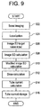
- Figure 9 shows a flow chart of the operation from the scout imaging to the tube current calculation as described above.
- scout imaging is conducted at Step 502.
- the subject 8 is fluoro-imaged in one or both of sagittal and lateral directions over a certain range in the body axis direction, and respective projections at positions on the body axis are acquired.
- the localization is for specifying scan start and end points on the body axis in a fluoroscopic image obtained by the scout imaging. This determines the length of the imaged range, and for a helical scan, determines a scan position for every pitch.
- the localization is performed by the user via the operating device 70.
- an image SD target value is input.
- the input is also performed by the user via the operating device 70. If a standard value prestored in the present apparatus is used for the image SD target value, input by default is possible.
- an image SD is calculated.
- a projection area is first obtained.
- respective projection areas are obtained from Equations (1) and (2); and when the scout imaging is conducted in one of these directions, a projection area is obtained by Equation (1) or (2) depending upon the direction.
- the image SD is then calculated from Equation (10) using the projection area(s).
- the image SD is calculated for every pitch of the helical scan. Calculations for values described below are also conducted in the same way.
- a modified image SD is calculated.
- sagittal and lateral center values are obtained from Equations (3) and (4), respectively, and an oval ratio is obtained from Equation (5).
- a sagittal or lateral center value is obtained from Equation (3) or (4)
- a lateral or sagittal center value is obtained from Equation (7)
- an oval ratio is obtained from Equation (8) or (9).
- An SD ratio is obtained from Equation (11) using the oval ratio, and the SD ratio is used to calculate the modified image SD from Equation (12).
- Step 512 dose is calculated.
- the dose calculation is performed according to Equation (15).
- the image SD target value input at Step 506 is used as image_SD target
- the two modified image SD's obtained as described above are used as image_SD predicted
- two doses are calculated.
- a tube current is calculated.
- the tube current calculation is performed according to Equation (16).
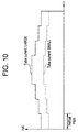
- the solid line in Figure 10 shows an exemplary tube current thus calculated. As shown, the tube current is obtained for every position on the body axis. The tube current indicated by the broken line will be explained later.
- the calculated values for the tube current are stored in the memory. Thus, the tube current is stored for every pitch of the helical scan.
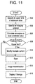
- FIG 11 is a flow chart of the general operation of the present apparatus.
- an upper limit of the exposure dose is specified.
- the specification is performed by the user via the display device 68 and operating device 70.
- a portion comprised of the display device 68 and operating device 70 is an embodiment of the setting means of the present invention.
- the exposure dose is set using a DLP (dose length product).
- the unit for the DLP is mGy . cm (milligray . centimeter).
- the upper limit for the DLP is specified as, for example, 300 mGy . cm.
- the upper limit for the DLP will be sometimes referred to as DLPu hereinbelow.
- an imaging protocol is specified.
- the protocol specification is achieved by the operation as shown in Figure 9.
- a tube current for the particular subject 8 is set.
- the imaging protocol desired by the user is specified, and the tube current is also set at a desired value.
- a predicted value for the exposure dose is calculated.
- the calculation of the exposure dose predicted value is achieved based on the tube current set value. Specifically, based on the tube current set value, a CTDlvol (CT dose index volume) is first calculated. The calculation of the CTDlvol based on the tube current is executed using a predefined algorithm.
- the CTDlvol is found from a pre-measured relationship between the CTDlvol and tube current using a phantom, for example.
- the unit for the CTDlvol is mGy.
- the exposure dose predicted value is obtained by multiplying the CTDlvol by the imaged length in the body axis direction.
- the exposure dose predicted value will be denoted by DLPc hereinbelow.
- the upper limit for the exposure dose may be set by the CTDlvol rather than the DLP.
- the exposure dose predicted value is also obtained as the CTDlvol.
- the upper limit and predicted value for the CTDlvol will be denoted by CTDlvolu and CTDlvolc, respectively, hereinbelow.
- Step 608 a decision is made on whether the predicted value is greater than the upper limit. If the predicted value is greater than the upper limit, the tube current is modified at Step 610.
- the tube current modification is achieved as follows: the upper limit DLPu is divided by the imaged length to obtain the CTDlvol, and the tube current is obtained based on the CTDlvol by inverting the aforementioned algorithm. Alternatively, the tube current may be obtained based on the pre-measured relationship between the CTDlvol and tube current. If the upper limit is set using the CTDlvol, the tube current can be obtained from the CTDlvol without the division by the imaged length.
- the data processing apparatus 60 for conducting the processing of Steps 606 - 610 is an embodiment of the modulating means of the present invention.
- the tube current modification may alternatively be conducted using the following equation. This facilitates the tube current modification.
- Step 612 a scan is conducted.
- the scan uses the tube current modified as described above. This allows a scan to be conducted without the exposure dose exceeding the upper limit. If the predicted value does not exceed the upper limit, the unmodified tube current is used to achieve a scan without the exposure dose exceeding the upper limit.
- image reconstruction is conducted. A reconstructed image is displayed on the display device 68 and stored in the memory at Step 616.
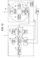
- Figure 12 shows a block diagram of an X-ray CT apparatus, which is an embodiment of the present invention.
- the configuration of the apparatus represents an embodiment of the apparatus in accordance with the present invention.
- parts similar to those shown in Figure 1 are designated by similar reference numerals, and explanation thereof will be omitted.
- the present apparatus comprises a communication interface 72.
- the communication interface 72 is disposed between an external communication network and the data processing apparatus 60.
- the data processing apparatus 60 exchanges data with the outside via the communication interface 72.
- Figure 13 shows a block diagram of a medical image network to which the present apparatus belongs.
- an image server 802 and a plurality of X-ray imaging apparatuses 812, 814, ..., 81n are connected via a communication circuit 820 to constitute a medical image network.
- the X-ray imaging apparatus 81 i (i: 2, 4, ..., n) is an X-ray CT apparatus, for example.
- the X-ray imaging apparatus is not limited to the X-ray CT apparatus but may be an appropriate imaging apparatus conducting imaging using X-rays, such as an X-ray fluoroscopic imaging apparatus.
- the image server 802 archives images captured by each X-ray imaging apparatus 81i (i: 2, 4, ..., n) and associated information. The information is accessible by each X-ray imaging apparatus 81i. If another image server 902 separate from the image server 802 is connected via the communication circuit, the X-ray imaging apparatus 81i can access the image server 902.
- the image servers 802 and 902 represent an embodiment of the server of the present invention.
- the present apparatus is configured to be capable of accessing the image server 802 (or 902 or both) to acquire historical information on a particular patient, calculating an X-ray dose to which the patient has been exposed thus far based on the information, and displaying the X-ray dose on the display device 68.
- the data processing apparatus 60 upon input of patient information at Step 702, acquires historical imaging data at Step 704, and calculates an exposure dose at Step 706.
- the exposure dose over the past year is found, for example, and is displayed at Step 708.
- the data processing apparatus 60 for executing the processing at Steps 704 and 706 is an embodiment of the calculating means of the present invention.
- the display device 68 for executing the display at Step 708 is an embodiment of the display means of the present invention.
- the user of the present apparatus can know the exposure dose to date for a patient.
- the exposure dose may be effectively used as reference data for present or future imaging to reduce the total amount of the exposure dose to the patient.
Landscapes
- Health & Medical Sciences (AREA)
- Life Sciences & Earth Sciences (AREA)
- Engineering & Computer Science (AREA)
- Medical Informatics (AREA)
- General Health & Medical Sciences (AREA)
- Optics & Photonics (AREA)
- Surgery (AREA)
- Veterinary Medicine (AREA)
- Biophysics (AREA)
- High Energy & Nuclear Physics (AREA)
- Public Health (AREA)
- Nuclear Medicine, Radiotherapy & Molecular Imaging (AREA)
- Animal Behavior & Ethology (AREA)
- Pathology (AREA)
- Radiology & Medical Imaging (AREA)
- Biomedical Technology (AREA)
- Heart & Thoracic Surgery (AREA)
- Molecular Biology (AREA)
- Physics & Mathematics (AREA)
- Toxicology (AREA)
- Pulmonology (AREA)
- Theoretical Computer Science (AREA)
- Apparatus For Radiation Diagnosis (AREA)
- X-Ray Techniques (AREA)
Abstract
Description


proj_measure: a center value known by measurement.
Claims (10)
- An X-ray controlling method for an X-ray imaging apparatus for projecting X-rays from an X-ray tube onto a subject to be imaged and detecting transmitted X-rays, and producing an image based on detected X-ray signals, comprising the steps of:setting an upper limit of an X-ray exposure dose to the subject to be imaged; andmodulating the tube current of the X-ray tube so that the exposure dose does not exceed the upper limit.
- The X-ray controlling method of claim 1, wherein said X-ray imaging apparatus is an X-ray CT apparatus.
- The X-ray controlling method of claim 2, wherein said X-ray CT apparatus conducts imaging by a helical scan.
- The X-ray controlling method of claim 2, wherein said step of modulating the tube current is achieved by: finding an exposure dose predicted value based on an imaging protocol; and modifying the tube current set value in the imaging protocol when the predicted value exceeds said upper limit.
- An X-ray imaging apparatus for projecting X-rays from an X-ray tube onto a subject to be imaged and detecting transmitted X-rays, and producing an image based on detected X-ray signals, comprising:a setting device for setting an upper limit of an X-ray exposure dose to the subject to be imaged; anda modulating device for modulating the tube current of the X-ray tube so that the exposure dose does not exceed the upper limit.
- The X-ray imaging apparatus of claim 5, wherein said X-ray imaging apparatus is an X-ray CT apparatus.
- The X-ray imaging apparatus of claim 6, wherein said X-ray CT apparatus conducts imaging by a helical scan.
- The X-ray imaging apparatus of claim 6, wherein said modulating device finds an exposure dose predicted value based on an imaging protocol, and modifies the tube current set value in the imaging protocol when the predicted value exceeds said upper limit.
- An X-ray imaging apparatus for projecting X-rays from an X-ray tube onto a subject to be imaged and detecting transmitted X-rays, and producing an image based on detected X-ray signals, comprising:a calculating device for calculating a historical X-ray exposure dose to the subject to be imaged; anda display device for displaying the calculated exposure dose.
- The X-ray imaging apparatus of claim 9, wherein said calculating device calculates the exposure dose based on historical imaging data for the subject to be imaged.
Applications Claiming Priority (2)
| Application Number | Priority Date | Filing Date | Title |
|---|---|---|---|
| JP2002343649 | 2002-11-27 | ||
| JP2002343649A JP2004173924A (en) | 2002-11-27 | 2002-11-27 | Method for controlling x-ray, and x-ray image photographing equipment |
Publications (2)
| Publication Number | Publication Date |
|---|---|
| EP1429588A2 true EP1429588A2 (en) | 2004-06-16 |
| EP1429588A3 EP1429588A3 (en) | 2006-02-01 |
Family
ID=32322005
Family Applications (1)
| Application Number | Title | Priority Date | Filing Date |
|---|---|---|---|
| EP03257441A Withdrawn EP1429588A3 (en) | 2002-11-27 | 2003-11-26 | X-ray controlling method and x-ray imaging apparatus |
Country Status (5)
| Country | Link |
|---|---|
| US (1) | US20040101105A1 (en) |
| EP (1) | EP1429588A3 (en) |
| JP (1) | JP2004173924A (en) |
| KR (1) | KR20040047641A (en) |
| CN (1) | CN1535100A (en) |
Cited By (4)
| Publication number | Priority date | Publication date | Assignee | Title |
|---|---|---|---|---|
| EP1943951A4 (en) * | 2005-09-15 | 2009-03-25 | Hitachi Medical Corp | X-ray ct device |
| EP1973469A4 (en) * | 2006-01-20 | 2009-12-30 | Wisconsin Alumni Res Found | METHOD AND APPARATUS FOR LOW-RADIATION COMPUTER-ASSISTED TOMOGRAPHY |
| CN101272736B (en) * | 2005-09-27 | 2012-06-20 | 皇家飞利浦电子股份有限公司 | Containment tubes and imaging systems employing same |
| US11288775B2 (en) | 2019-11-27 | 2022-03-29 | GE Precision Healthcare LLC | Methods and systems for parametric noise modulation in x-ray imaging |
Families Citing this family (25)
| Publication number | Priority date | Publication date | Assignee | Title |
|---|---|---|---|---|
| JP2005168870A (en) * | 2003-12-12 | 2005-06-30 | Shimadzu Corp | X-ray CT system |
| US7082183B2 (en) * | 2004-07-21 | 2006-07-25 | General Electric Company | Computed tomography dose indexing phantom selection for dose reporting |
| JP2006055635A (en) * | 2004-07-23 | 2006-03-02 | Toshiba Corp | X-ray computed tomography system |
| JP4731151B2 (en) * | 2004-10-22 | 2011-07-20 | 株式会社日立メディコ | X-ray tube current determination method and X-ray CT apparatus |
| JP5161418B2 (en) * | 2005-06-09 | 2013-03-13 | 株式会社東芝 | X-ray irradiation dose management apparatus and X-ray diagnostic imaging apparatus |
| JP2007054372A (en) * | 2005-08-25 | 2007-03-08 | Ge Medical Systems Global Technology Co Llc | X-ray ct apparatus |
| US20070076842A1 (en) * | 2005-09-30 | 2007-04-05 | Tkaczyk John E | Adaptable energy discriminating computed tomography system |
| DE102005056701B4 (en) * | 2005-11-28 | 2007-10-04 | Siemens Ag | Method and device for planning a treatment |
| JP2008119094A (en) * | 2006-11-09 | 2008-05-29 | Ge Medical Systems Global Technology Co Llc | X-ray tube driving method and x-ray ct apparatus |
| CN101327128B (en) * | 2007-06-22 | 2010-12-08 | Ge医疗系统环球技术有限公司 | Scan and detection device of X ray CT device as well as system and operation method thereof |
| CN101472381B (en) * | 2007-12-29 | 2013-03-27 | Ge医疗系统环球技术有限公司 | Method for controlling X ray exposure of X ray CT system |
| CN101686596B (en) * | 2008-09-24 | 2012-10-17 | 上海西门子医疗器械有限公司 | Bulb current modulating method and a bulb current modulating system |
| JP5898081B2 (en) * | 2010-09-07 | 2016-04-06 | 株式会社日立メディコ | X-ray CT system |
| US9254107B2 (en) | 2010-09-07 | 2016-02-09 | Hitachi Medical Corporation | X-ray CT apparatus and tube current determination method |
| JP5740379B2 (en) * | 2012-10-22 | 2015-06-24 | 株式会社東芝 | X-ray irradiation dose management apparatus and X-ray diagnostic imaging apparatus |
| JP6117524B2 (en) | 2012-11-22 | 2017-04-19 | 富士フイルム株式会社 | Radiographic imaging system, radiographic imaging method and program |
| CN104545966B (en) | 2014-09-02 | 2017-06-06 | 沈阳东软医疗系统有限公司 | A kind of scan method and device based on scanning dose |
| CN104644203B (en) * | 2014-09-02 | 2018-01-23 | 沈阳东软医疗系统有限公司 | A kind of dose-modulated scan method and device |
| CN104287768A (en) | 2014-09-30 | 2015-01-21 | 沈阳东软医疗系统有限公司 | Method and system for controlling CT scan dose |
| JP2016162525A (en) * | 2015-02-27 | 2016-09-05 | 東芝電子管デバイス株式会社 | X-ray tube device |
| US9962134B2 (en) * | 2015-10-28 | 2018-05-08 | Medtronic Navigation, Inc. | Apparatus and method for maintaining image quality while minimizing X-ray dosage of a patient |
| JP2017213288A (en) * | 2016-06-02 | 2017-12-07 | 株式会社ジェイマックシステム | Radiation imaging support system, composite radiation imaging support method, and composite radiation imaging support program |
| EP3597106A1 (en) | 2018-07-19 | 2020-01-22 | Koninklijke Philips N.V. | Ct scan parameter optimization |
| US12458302B2 (en) * | 2021-05-05 | 2025-11-04 | Koninklijke Philips N.V. | Systems and methods for processing and visualizing tube current modulations in medical imaging devices |
| US12490951B2 (en) * | 2022-05-16 | 2025-12-09 | Medtronic Navigation, Inc. | Methods and systems for guiding user to perform medical imaging |
Family Cites Families (23)
| Publication number | Priority date | Publication date | Assignee | Title |
|---|---|---|---|---|
| JPH0636793B2 (en) * | 1988-05-20 | 1994-05-18 | 株式会社東芝 | X-ray CT scan |
| JP3335679B2 (en) * | 1992-11-04 | 2002-10-21 | 東芝医用システムエンジニアリング株式会社 | X-ray management device |
| US5450462A (en) * | 1993-11-19 | 1995-09-12 | General Electric Company | Modulation of x-ray tube current during CT scanning with modulation limit |
| US5400378A (en) * | 1993-11-19 | 1995-03-21 | General Electric Company | Dynamic dose control in multi-slice CT scan |
| US5379333A (en) * | 1993-11-19 | 1995-01-03 | General Electric Company | Variable dose application by modulation of x-ray tube current during CT scanning |
| US5485494A (en) * | 1994-08-03 | 1996-01-16 | General Electric Company | Modulation of X-ray tube current during CT scanning |
| US5696807A (en) * | 1996-09-05 | 1997-12-09 | General Electric Company | Methods and apparatus for modulating x-ray tube current |
| JPH10155778A (en) * | 1996-11-29 | 1998-06-16 | Shimadzu Corp | X-ray diagnostic imaging device |
| US5822393A (en) * | 1997-04-01 | 1998-10-13 | Siemens Aktiengesellschaft | Method for adaptively modulating the power level of an x-ray tube of a computer tomography (CT) system |
| JP3244458B2 (en) * | 1997-09-30 | 2002-01-07 | ジーイー横河メディカルシステム株式会社 | X-ray tomography equipment |
| DE19802572A1 (en) * | 1998-01-23 | 1999-08-05 | Siemens Health Service Gmbh & | Medical system architecture |
| US6249565B1 (en) * | 1998-06-18 | 2001-06-19 | Siemens Medical Systems, Inc. | Fractional monitor unit radiation delivery control using dose rate modulation |
| US6385280B1 (en) * | 1998-08-18 | 2002-05-07 | Siemens Aktiengesellschaft | X-ray computed tomography apparatus with modulation of the x-ray power of the x-ray source |
| US6141402A (en) * | 1998-08-25 | 2000-10-31 | General Electric Company | Methods and apparatus for dose verification in an imaging system |
| DE19919423B4 (en) * | 1999-04-28 | 2005-07-28 | Siemens Ag | Computed tomography (CT) device |
| JP3977972B2 (en) * | 1999-12-13 | 2007-09-19 | ジーイー・メディカル・システムズ・グローバル・テクノロジー・カンパニー・エルエルシー | Scanning condition determination method for tomography, tomography method and X-ray CT apparatus |
| WO2001054463A1 (en) * | 2000-01-24 | 2001-07-26 | Mamea Imaging Ab | Method and arrangement relating to an x-ray imaging apparatus |
| JP4519254B2 (en) * | 2000-04-03 | 2010-08-04 | 株式会社日立メディコ | X-ray CT system |
| US6590953B2 (en) * | 2000-09-12 | 2003-07-08 | Hitachi Medical Corporation | X-ray CT scanner |
| JP4532005B2 (en) * | 2001-03-09 | 2010-08-25 | 株式会社日立メディコ | X-ray CT apparatus and image display method thereof |
| US6904127B2 (en) * | 2001-11-21 | 2005-06-07 | General Electric Company | System and method of medical imaging having default noise index override capability |
| US20030128801A1 (en) * | 2002-01-07 | 2003-07-10 | Multi-Dimensional Imaging, Inc. | Multi-modality apparatus for dynamic anatomical, physiological and molecular imaging |
| US7254623B1 (en) * | 2002-04-16 | 2007-08-07 | General Electric Company | Method and apparatus for reducing x-ray dosage in CT imaging prescription |
-
2002
- 2002-11-27 JP JP2002343649A patent/JP2004173924A/en active Pending
-
2003
- 2003-11-19 US US10/717,419 patent/US20040101105A1/en not_active Abandoned
- 2003-11-26 EP EP03257441A patent/EP1429588A3/en not_active Withdrawn
- 2003-11-26 KR KR1020030084293A patent/KR20040047641A/en not_active Withdrawn
- 2003-11-27 CN CNA2003101240860A patent/CN1535100A/en active Pending
Cited By (5)
| Publication number | Priority date | Publication date | Assignee | Title |
|---|---|---|---|---|
| EP1943951A4 (en) * | 2005-09-15 | 2009-03-25 | Hitachi Medical Corp | X-ray ct device |
| CN101272736B (en) * | 2005-09-27 | 2012-06-20 | 皇家飞利浦电子股份有限公司 | Containment tubes and imaging systems employing same |
| EP1973469A4 (en) * | 2006-01-20 | 2009-12-30 | Wisconsin Alumni Res Found | METHOD AND APPARATUS FOR LOW-RADIATION COMPUTER-ASSISTED TOMOGRAPHY |
| US7688938B2 (en) | 2006-01-20 | 2010-03-30 | Wisconsin Alumni Research Foundation | Method and apparatus for low dose computed tomography |
| US11288775B2 (en) | 2019-11-27 | 2022-03-29 | GE Precision Healthcare LLC | Methods and systems for parametric noise modulation in x-ray imaging |
Also Published As
| Publication number | Publication date |
|---|---|
| US20040101105A1 (en) | 2004-05-27 |
| EP1429588A3 (en) | 2006-02-01 |
| KR20040047641A (en) | 2004-06-05 |
| CN1535100A (en) | 2004-10-06 |
| JP2004173924A (en) | 2004-06-24 |
Similar Documents
| Publication | Publication Date | Title |
|---|---|---|
| US20040101105A1 (en) | X-ray controlling method and X-ray imaging apparatus | |
| US6987828B2 (en) | Transmitted X-ray data acquisition system and X-ray computed tomography system | |
| EP1304077B1 (en) | X-ray computed tomography apparatus | |
| US6744846B2 (en) | Method and apparatus for automatic exposure control in CT scanning | |
| US7145982B2 (en) | X-ray CT apparatus and method of calculating blood-flow information | |
| JP4387638B2 (en) | X-ray computed tomography diagnostic equipment | |
| JP4345960B2 (en) | Method and apparatus for adjusting and transforming radiation filter correction during radiographic imaging | |
| EP1737346B1 (en) | Dynamic dose control for computed tomography | |
| JP3124254B2 (en) | Radiation tomography equipment | |
| JP4159188B2 (en) | Tube current adjusting method and apparatus, and X-ray CT apparatus | |
| JP2004180715A (en) | X-ray computed tomography equipment | |
| JPH10149895A (en) | Method and system for modulating x-ray tube current and system for dynamically adjusting at least one component of a computed tomography imaging system | |
| JP2009125250A (en) | X-ray ct equipment | |
| EP1959835B1 (en) | Systems and methods for scanning and data acquisition in computed tomography (ct) applications | |
| CN101193593A (en) | X-ray CT device | |
| JP5697422B2 (en) | X-ray diagnostic equipment | |
| US6917665B2 (en) | X-ray computed tomography apparatus | |
| EP0985379B1 (en) | Radiation tomography method and apparatus | |
| JP4260966B2 (en) | X-ray computed tomography system | |
| JP4732592B2 (en) | Optimized CT protocol | |
| JP3249088B2 (en) | X-ray irradiation alignment method and X-ray tomographic imaging apparatus | |
| JP2008221016A (en) | X-ray computed tomography diagnostic equipment | |
| JP3950612B2 (en) | X-ray CT system | |
| JP2003310599A (en) | X-ray ct system | |
| EP1952766B1 (en) | X-ray CT device |
Legal Events
| Date | Code | Title | Description |
|---|---|---|---|
| PUAI | Public reference made under article 153(3) epc to a published international application that has entered the european phase |
Free format text: ORIGINAL CODE: 0009012 |
|
| AK | Designated contracting states |
Kind code of ref document: A2 Designated state(s): AT BE BG CH CY CZ DE DK EE ES FI FR GB GR HU IE IT LI LU MC NL PT RO SE SI SK TR |
|
| AX | Request for extension of the european patent |
Extension state: AL LT LV MK |
|
| PUAL | Search report despatched |
Free format text: ORIGINAL CODE: 0009013 |
|
| AK | Designated contracting states |
Kind code of ref document: A3 Designated state(s): AT BE BG CH CY CZ DE DK EE ES FI FR GB GR HU IE IT LI LU MC NL PT RO SE SI SK TR |
|
| AX | Request for extension of the european patent |
Extension state: AL LT LV MK |
|
| AKX | Designation fees paid | ||
| REG | Reference to a national code |
Ref country code: DE Ref legal event code: 8566 |
|
| STAA | Information on the status of an ep patent application or granted ep patent |
Free format text: STATUS: THE APPLICATION IS DEEMED TO BE WITHDRAWN |
|
| 18D | Application deemed to be withdrawn |
Effective date: 20060701 |