EP1429571B1 - Radio base apparatus, communication channel allocation method, and allocation program - Google Patents
Radio base apparatus, communication channel allocation method, and allocation program Download PDFInfo
- Publication number
- EP1429571B1 EP1429571B1 EP02762865A EP02762865A EP1429571B1 EP 1429571 B1 EP1429571 B1 EP 1429571B1 EP 02762865 A EP02762865 A EP 02762865A EP 02762865 A EP02762865 A EP 02762865A EP 1429571 B1 EP1429571 B1 EP 1429571B1
- Authority
- EP
- European Patent Office
- Prior art keywords
- base station
- slot
- control
- signal
- communication
- Prior art date
- Legal status (The legal status is an assumption and is not a legal conclusion. Google has not performed a legal analysis and makes no representation as to the accuracy of the status listed.)
- Expired - Fee Related
Links
Images


Classifications
-
- H—ELECTRICITY
- H04—ELECTRIC COMMUNICATION TECHNIQUE
- H04W—WIRELESS COMMUNICATION NETWORKS
- H04W72/00—Local resource management
- H04W72/04—Wireless resource allocation
-
- H—ELECTRICITY
- H04—ELECTRIC COMMUNICATION TECHNIQUE
- H04B—TRANSMISSION
- H04B7/00—Radio transmission systems, i.e. using radiation field
- H04B7/02—Diversity systems; Multi-antenna system, i.e. transmission or reception using multiple antennas
- H04B7/04—Diversity systems; Multi-antenna system, i.e. transmission or reception using multiple antennas using two or more spaced independent antennas
- H04B7/08—Diversity systems; Multi-antenna system, i.e. transmission or reception using multiple antennas using two or more spaced independent antennas at the receiving station
- H04B7/0837—Diversity systems; Multi-antenna system, i.e. transmission or reception using multiple antennas using two or more spaced independent antennas at the receiving station using pre-detection combining
-
- H—ELECTRICITY
- H04—ELECTRIC COMMUNICATION TECHNIQUE
- H04B—TRANSMISSION
- H04B7/00—Radio transmission systems, i.e. using radiation field
- H04B7/02—Diversity systems; Multi-antenna system, i.e. transmission or reception using multiple antennas
- H04B7/04—Diversity systems; Multi-antenna system, i.e. transmission or reception using multiple antennas using two or more spaced independent antennas
- H04B7/08—Diversity systems; Multi-antenna system, i.e. transmission or reception using multiple antennas using two or more spaced independent antennas at the receiving station
-
- H—ELECTRICITY
- H04—ELECTRIC COMMUNICATION TECHNIQUE
- H04W—WIRELESS COMMUNICATION NETWORKS
- H04W72/00—Local resource management
- H04W72/50—Allocation or scheduling criteria for wireless resources
- H04W72/54—Allocation or scheduling criteria for wireless resources based on quality criteria
- H04W72/542—Allocation or scheduling criteria for wireless resources based on quality criteria using measured or perceived quality
-
- H—ELECTRICITY
- H04—ELECTRIC COMMUNICATION TECHNIQUE
- H04W—WIRELESS COMMUNICATION NETWORKS
- H04W88/00—Devices specially adapted for wireless communication networks, e.g. terminals, base stations or access point devices
- H04W88/08—Access point devices
-
- H—ELECTRICITY
- H04—ELECTRIC COMMUNICATION TECHNIQUE
- H04W—WIRELESS COMMUNICATION NETWORKS
- H04W24/00—Supervisory, monitoring or testing arrangements
-
- H—ELECTRICITY
- H04—ELECTRIC COMMUNICATION TECHNIQUE
- H04W—WIRELESS COMMUNICATION NETWORKS
- H04W28/00—Network traffic management; Network resource management
- H04W28/02—Traffic management, e.g. flow control or congestion control
- H04W28/06—Optimizing the usage of the radio link, e.g. header compression, information sizing, discarding information
-
- H—ELECTRICITY
- H04—ELECTRIC COMMUNICATION TECHNIQUE
- H04W—WIRELESS COMMUNICATION NETWORKS
- H04W52/00—Power management, e.g. TPC [Transmission Power Control], power saving or power classes
- H04W52/02—Power saving arrangements
- H04W52/0203—Power saving arrangements in the radio access network or backbone network of wireless communication networks
- H04W52/0206—Power saving arrangements in the radio access network or backbone network of wireless communication networks in access points, e.g. base stations
-
- H—ELECTRICITY
- H04—ELECTRIC COMMUNICATION TECHNIQUE
- H04W—WIRELESS COMMUNICATION NETWORKS
- H04W72/00—Local resource management
- H04W72/04—Wireless resource allocation
- H04W72/044—Wireless resource allocation based on the type of the allocated resource
- H04W72/0446—Resources in time domain, e.g. slots or frames
-
- H—ELECTRICITY
- H04—ELECTRIC COMMUNICATION TECHNIQUE
- H04W—WIRELESS COMMUNICATION NETWORKS
- H04W72/00—Local resource management
- H04W72/20—Control channels or signalling for resource management
- H04W72/21—Control channels or signalling for resource management in the uplink direction of a wireless link, i.e. towards the network
-
- H—ELECTRICITY
- H04—ELECTRIC COMMUNICATION TECHNIQUE
- H04W—WIRELESS COMMUNICATION NETWORKS
- H04W74/00—Wireless channel access, e.g. scheduled or random access
- H04W74/04—Scheduled or contention-free access
-
- Y—GENERAL TAGGING OF NEW TECHNOLOGICAL DEVELOPMENTS; GENERAL TAGGING OF CROSS-SECTIONAL TECHNOLOGIES SPANNING OVER SEVERAL SECTIONS OF THE IPC; TECHNICAL SUBJECTS COVERED BY FORMER USPC CROSS-REFERENCE ART COLLECTIONS [XRACs] AND DIGESTS
- Y02—TECHNOLOGIES OR APPLICATIONS FOR MITIGATION OR ADAPTATION AGAINST CLIMATE CHANGE
- Y02D—CLIMATE CHANGE MITIGATION TECHNOLOGIES IN INFORMATION AND COMMUNICATION TECHNOLOGIES [ICT], I.E. INFORMATION AND COMMUNICATION TECHNOLOGIES AIMING AT THE REDUCTION OF THEIR OWN ENERGY USE
- Y02D30/00—Reducing energy consumption in communication networks
- Y02D30/70—Reducing energy consumption in communication networks in wireless communication networks
Definitions
- the present invention relates to an apparatus for a radio base station, and a method and a program of controlling communication channel allocation in a mobile communication system.
- a base station In a mobile communication system (such as Personal Handyphone System: abbreviated as PHS hereinafter) rapidly developed in recent years, a base station is practically used which enables transmission and reception with directivity by performing so-called adaptive array processing using an array antenna formed with a plurality of antennas to attain a good communication quality.
- PHS Personal Handyphone System
- a communication system called PDMA (Path Division Multiple Access) system or SDMA (Space Division Multiple Access) system also becomes feasible wherein a spatial multiple access of wireless terminals (terminals or personal stations) of a plurality of users to a radio base station (base station or cellular station) is possible by spatially dividing a time slot of the same frequency to enhance utilization efficiency of radio wave frequency.
- PDMA Pulth Division Multiple Access
- SDMA Space Division Multiple Access
- an up-link signal from an antenna on each user terminal is received by an array antenna on a base station, and is separated and extracted with reception directivity by the adaptive array processing.
- a down-link signal from the base station to the terminal is transmitted from the array antenna with transmission directivity to the antenna on the terminal.
- Document US 5,778,318 discloses a method for allocating control channels in a radio system having base stations and subscriber stations communicating with respective ones of the base stations on control and traffic channels.
- traffic channels are allocated for control channel use so as to distribute the control channel operation between a greater number of channels, the channels allocated for control channel use being indicated to the subscriber stations and control channel operation is performed on the control channels allocated in a distributed manner.
- the base station performing down-link transmission directivity control for the terminal using such adaptive array processing is preferred to as "an adaptive array base station”.
- TDMA system As the communication system of the above-described PHS, TDMA system is adopted, wherein a frame (5 ms) consisting of respective four slots (one slot: 625 ⁇ s) for transmission and reception is used as a base unit. SDMA system uses the same frame structure.
- This communication system of PHS is standardized, for example, as "a second generation cordless telephone system".
- Fig. 13 is a schematic diagram showing a structure of a signal transmitted and received between a terminal and a PHS base station.
- a signal of one frame is divided into eight slots and, for example, the former four slots are used for reception while the latter four slots are used for transmission.
- Each slot includes 120 symbols.
- a prescribed number of frames such as 20 frames, each having such a structure, form one cycle. That is, in the PHS system, one base station communicates with a terminal within its service area using a control channel once in every prescribed number of frames such as once in every 20 frames, and the terminal obtains information such as whether the terminal can make a call at the present position.
- a set of one slot for reception and one slot for transmission is allocated to the control channel while the remaining three sets of slots are respectively allocated to traffic channels for three users, for example, in the first frame of the 20 frames cycle.
- the set of slots corresponding to the control channel is kept empty, and the remaining three sets are successively allocated to the traffic channels for three users.
- a link channel is first established by the control channel, followed by interference wave (U wave: Undesired wave) measurement processing and setting of a traffic condition with an allocated channel, and then a speech starts.
- interference wave U wave: Undesired wave
- a speech starts.
- Fig. 14 shows such a traffic sequence flow of the PHS system. Brief description thereof will be given referring to Fig. 14 .
- a link channel establishment request signal (LCH establishment request signal) is transmitted from a PHS terminal to a base station using a C channel (control channel: CCH).
- the PHS base station detects (carrier sense) an empty channel (empty traffic channel: empty T channel) and, using the C channel, transmits to the PHS terminal a link channel allocation signal (LCH allocation signal) specifying the empty T channel.
- a measurement is performed to determine if the specified T channel receives an interference wave signal having power equal to or higher than a certain value, based on the link channel information received from the PHS base station.
- the interference wave signal having power equal to or higher than the certain value is not detected, that is, when the specified T channel is not used by another PHS base station, a synchronous burst signal is transmitted to the base station using the specified T channel, and then the base station transmits the synchronous burst signal back to the terminal to complete the establishment of synchronization.
- the PHS terminal repeats the control procedure by again transmitting the link channel establishment request signal.
- a connection of a communication channel between a terminal and a base station is performed as such using a channel with a small interference wave which can obtain a good communication characteristic.
- control channel CCH When the control channel CCH is used for communication only in one frame of 20 frames cycle, for example, and is kept empty in the remaining 19 frames as described above, however, utilization efficiency of radio wave decreases. The efficiency is especially low in a condition of heavy traffic.
- an object of the present invention is to provide an apparatus for a radio base station, and a method and a program of controlling communication channel allocation which can enhance the utilization efficiency of radio wave in a mobile communication system wherein a plurality of terminals are connected to a base station.
- An aspect of the present invention discloses an apparatus for a radio base station in a mobile communication system, wherein a signal transmitted and received in the mobile communication system is divided into a plurality of frames each including a control slot for transferring at least one control signal and a plurality of communication slots for information communication.
- the apparatus includes reception level sensing means for monitoring a signal level of a control slot from a peripheral base station, and channel allocation means for allocating the control slot for the information communication in response to a sensing result of the reception level sensing means when a connection is requested from a terminal device.
- the channel allocation means preferably allocates the control slot for the information communication in response to a presence of at least a prescribed number of other peripheral base stations capable of receiving signals of the control slots, which presence is determined from a sensing result of the reception level sensing means.
- the channel allocation means preferably allocates the control slot for the information communication in response to a signal level of the control slot from another peripheral base station being equal to or higher than a prescribed value, which signal level is determined from a sensing result of the reception level sensing means.
- Another aspect of the present invention discloses a communication channel allocation method in an apparatus for a radio base station in a mobile communication system, wherein a signal transmitted and received in the mobile communication system is divided into a plurality of frames each including a control slot for transferring at least one control signal and a plurality of communication slots for information communication.
- the method includes the steps of: monitoring a signal level of a control slot from a peripheral base station; and allocating the control slot for the information communication in response to a sensing result of reception level when a connection is requested from a terminal device.
- the allocating step preferably includes the steps of searching or an empty communication slot of the radio base station and, when there is no empty communication slot of the radio base station, allocating the control slot for the information communication in response to a presence of at least a prescribed number of other peripheral base stations capable of receiving signals of the control slots.
- the allocating step preferably includes the steps of searching for an empty communication slot of the radio base station and, when there is no empty communication slot of the radio base station, allocating the control slot for the information communication in response to a signal level of the control slot from another peripheral base station being equal to or higher than a prescribed value.
- a further aspect of the present invention discloses a communication channel allocation program in an apparatus for a radio base station in a mobile communication system, wherein a signal transmitted and received in the mobile communication system is divided into a plurality of frames each including a control slot for transferring at least one control signal and a plurality of communication slots for information communication.
- the program makes a computer execute the steps of: monitoring a signal level of a control slot from a peripheral base station; and allocating the control slot for the information communication in response to a sensing result of reception level when a connection is requested from a terminal device.
- the allocating step preferably includes the steps of searching for an empty communication slot of the radio base station and, when there is no empty communication slot of the radio base station, allocating the control slot for the information communication in response to a presence of at least a prescribed number of other peripheral base stations capable of receiving signals of the control slots.
- the allocating step preferably includes the steps of searching for an empty communication slot of the radio base station and, when there is no empty communication slot of the radio base station, allocating the control slot for the information communication in response to a signal level of the control slot from another peripheral base station being equal to or higher than a prescribed value.
- a further aspect of the present invention discloses an apparatus for a radio base station in a mobile communication system, wherein a signal transmitted and received in the mobile communication system is divided into a plurality of frames each including at least one control slot for transferring a control signal and a plurality of communication slots for information communication.
- the apparatus includes reception level sensing means for monitoring a signal level and reception timing of a control slot from a peripheral base station, channel allocation means for allocating the control slot for the information communication in response to a sensing result of the reception level sensing means when a connection is requested from a terminal device, storing means for storing the sensing result of the reception level sensing means when a connection is requested from the terminal device, and control means for resuming transmission of the control signal based on the sensing result stored in the storing means in response to an occurrence of an empty slot within the frame after the control slot is allocated for the information communication.
- the control means When the empty slot is the control slot, the control means preferably synchronizes sending timing of a signal of the control slot with the peripheral base station based on the sensing result stored in the storing means to resume transmission of the control signal.
- control means When the empty slot is not the control slot, the control means preferably i) reallocates a terminal performing the information communication in the control slot to the empty slot, and ii) synchronizes sending timing of a signal of the control slot with the peripheral base station based on the sensing result stored in the storing means to resume transmission of the control signal.
- a further aspect of the present invention discloses a communication channel allocation method in an apparatus for a radio base station in a mobile, communication system, wherein a signal transmitted and received in the mobile communication system is divided into a plurality of frames each including a control slot for transferring at least one control signal and a plurality of communication slots for information communication.
- the method includes the steps of: monitoring a signal level and reception timing of a control slot from a peripheral base station; allocating the control slot for the information communication in response to the signal level of the control slot from the peripheral base station when a connection is requested from a terminal device; storing the signal level and the reception timing of the control slot from the peripheral base station when a connection is requested from the terminal device; and resuming transmission of the control signal based on the stored signal level and the reception timing of the control slot from the peripheral base station in response to an occurrence of an empty slot within the frame after the control slot is allocated for the information communication.
- the resuming step preferably includes the step of synchronizing sending timing of a signal of the control slot with the peripheral base station based on the stored signal level and the reception timing of the control slot from the peripheral base station to resume transmission of the control signal.
- the resuming step preferably includes the steps of reallocating a terminal performing the information communication in the control slot to the empty slot, and synchronizing sending timing of a signal of the control slot with the peripheral base station based on the sensing result stored in the storing means to resume transmission of the control signal.
- a further aspect of the present invention discloses a communication channel allocation program in an apparatus for a radio base station in a mobile communication system, wherein a signal transmitted and received in the mobile communication system is divided into a plurality of frames each including a control slot for transferring at least one control signal and a plurality of communication slots for information communication.
- the program makes a computer execute the steps of: monitoring a signal level and reception timing of a control slot from a peripheral base station; allocating the control slot for the information communication in response to the signal level of the control slot from the peripheral base station when a connection is requested from a terminal device; storing the signal level and the reception timing of the control slot from the peripheral base station when a connection is requested from the terminal device; and resuming transmission of the control signal based on the stored signal level and the reception timing of the control slot from the peripheral base station in response to an occurrence of an empty slot within the frame after the control slot is allocated for the information communication.
- the resuming step preferably includes the step of synchronizing sending timing of a signal of the control slot with the peripheral base station based on the stored signal level and the reception timing of the control slot from the peripheral base station to resume transmission of the controls signal.
- the resuming step preferably includes the steps of reallocating a terminal performing the information communication in the control slot to the empty slot, and synchronizing sending timing of a signal of the control slot with the peripheral base station based on the sensing result stored in the storing means to resume transmission of the control signal.
- a further aspect of the present invention discloses an apparatus for a radio base station in a mobile communication system, wherein a signal transmitted and received in the mobile communication system is divided into a plurality of frames each including at least one control slot for transferring a control signal and a plurality of communication slots for information communication.
- the apparatus includes a plurality of antennas, reception directivity control means for separating a signal from a desired terminal device by adaptive array processing based on signals from the plurality of antennas, and control means for allocating the control slot for the information communication when connections are requested from terminal devices which are equal to or larger in number than the capacity of the communication slot.
- the reception directivity control means controls the reception directivity with a prescribed number of the plurality of antennas, and receives the control signal with the remaining antenna(s).
- the apparatus for radio base station further includes transmission directivity control means for producing a transmission signal having directivity for a desired terminal device by the adaptive array processing.
- the transmission directivity control means controls transmission directivity with a prescribed number of the plurality of antennas, and transmits the control signal with the remaining antenna(s).
- a further aspect of the present invention discloses a communication channel allocation method in an apparatus for a radio base station which transmits and receives a signal having directivity with a desired terminal device by adaptive array processing based on signals from a plurality of antennas, wherein a signal transmitted and received in a mobile communication system is divided into a plurality of frames each including a control slot for transferring at least one control signal and a plurality of communication slots for information communication.
- the method includes the steps of: allocating the control slot for the information communication in response to a signal level of the control slot from a peripheral base station when a connection is requested from a terminal device; and controlling transmission and reception directivity with a prescribed number of the plurality of antennas while receiving the control signal with the remaining antenna(s) when the control slot is allocated for the information communication.
- a further aspect of the present invention discloses a communication channel allocation program in an apparatus for a radio base station which transmits and receives a signal having directivity with a desired terminal device by adaptive array processing based on signals from a plurality of antennas in a mobile communication system, wherein a signal transmitted and received in the mobile communication system is divided into a plurality of frames each including a control slot for transferring at least one control signal and a plurality of communication slots for information communication.
- the program makes a computer execute the steps of: allocating the control slot for the information communication in response to a signal level of the control slot from a peripheral base station when a connection is requested from a terminal device; and controlling transmission and reception directivity with a prescribed number of the plurality of antennas while receiving the control signal with the remaining antenna(s) when the control slot is allocated for the information communication.
- Fig. 1 is a schematic block diagram showing a configuration of an adaptive array base station 1000 according to the embodiment of the present invention.
- base station 1000 according to the present invention is described as an adaptive array base station in the following description, the present invention is not limited to the adaptive array base station.
- the present invention is applicable to a base station of a mobile communication system wherein both a communication channel for information communication of a user such as a speech and a control channel for controlling, for example, a link establishment are allocated to a plurality of slots in one frame.
- the present invention is applicable to a base station communicating in SDMA system, wherein a spatial multiple access is possible, as long as it is an adaptive array base station.
- adaptive array base station 1000 includes an array antenna formed with a plurality of antennas such as antennas #1-#4.
- Antennas #1-#4 are respectively connected to a radio unit 10. During reception, signals received at antennas #1-#4 are fed to a reception unit 20 via radio unit 10. Therein, various analog signal processing such as amplification, frequency conversion and so on is performed on the received signals fed to reception unit 20, and the signals are then converted to digital signals by an A/D converters (not shown). Furthermore, a signal of each user is separated and extracted in reception unit 20 by adaptive array processing controlled with a control unit 40. The received signal of each user which is separated and extracted is then fed to a demodulation unit 30, and required demodulation processing and time-division processing are performed to reconstruct the original signal, and then the result is output to a public network (not shown).
- a public network not shown
- a reception level sensing unit 50 receives a signal from reception unit 20 and, as will be described below, outputs to control unit 40 a power level (reception level) of each received signal at antennas #1-#4, especially the received signal of control channel CCH from another base station.
- a store unit 60 receives and stores information from control unit 40 such as a slot number of control channel CCH, transmission timing of a frame and so on, which information will be necessary for base station 1000 to resume transmission of control channel CCH after the control channel is allocated as a traffic channel (TCH).
- control unit 40 such as a slot number of control channel CCH, transmission timing of a frame and so on, which information will be necessary for base station 1000 to resume transmission of control channel CCH after the control channel is allocated as a traffic channel (TCH).
- TCH traffic channel
- a channel allocation computing unit 70 determines whether there is an empty traffic channel and whether control channel CCH can be allocated as a traffic channel, and notifies control unit 40 of the result while storing channel allocation information in store unit 60.
- LCH link channel
- a transmission provide from the public network (not shown) is fed to a modulation unit 80 via control unit 40.
- Required time-division processing and modulation processing are performed, and the result is fed to a transmission unit 90.
- transmission unit 90 down-link transmission directivity to the signal to be transmitted is controlled by adaptive array processing.
- the signal is converted to an analog signal by a D/A converter (not shown), and various analog signal processing necessary for radio transmission such as amplification, frequency conversion and so on is performed.
- signals from transmission unit 90 are fed to antennas #1-#4 via radio unit 10 and are transmitted to a desired terminal from antennas #1-#4.
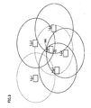
- Fig. 2 is a first schematic diagram showing a state of radio waves of base station 1000 and peripheral base stations.
- baste station 1000 when a link channel (LCH) establishment request is received from a terminal within a service area of base station 1000, the number of peripheral base stations transmitting signals of control channels CCHs at receivable level and level of individual control channel CCH received from the peripheral base station are determined.
- LCH link channel
- Fig. 2 shows, in a solid line, coverage of radio wave of a base station which is transmitting a signal of control channel CCH receivable at the position of base station 1000.
- signals of control channels CCHs from two out of five peripheral base stations are receivable at the position of base station 1000.
- Fig. 3 is a second schematic diagram showing a state of radio waves of base station 1000 and peripheral base stations.
- Base stations are arranged in higher density in a heavy traffic area such as an urban area.
- the situation may be such that, signals of control channels CCHs from, for example, four out of five peripheral base stations are receivable at the position of base station 1000 where base stations are arranged in higher density as shown in Fig. 3 .
- control channel CCH is stopped in base station 1000 and control channel CCH is shifted to traffic channel in all 20 frames, for example, and when a terminal other than the terminal currently connecting to base station 1000 is to originate a new call, because a control signal of a control channel from another peripheral base station can be received within the service area of base station 1000.
- channel allocation computing unit 70 of base station 1000 not only determines whether there is an empty traffic channel, but also determines whether control channel CCH of base station 1000 can be allocated as a traffic channel, based on the number of peripheral base stations transmitting receivable signals of control channels CCHs or a level of control channel CCH received from a peripheral base station.
- Fig. 4 is a flow chart showing operations executed by channel allocation computing unit 70 of adaptive array base station 1000 for channel allocation.
- This processing can also be performed by a digital signal processor. (DSP) within base station 1000, which is not shown, based on software according to the flow chart shown in Fig. 4 .
- the DSP reads a program including each step of the flow chart shown in Fig. 4 from a memory, which is not shown, and executes the same.
- This program can also be downloaded from a center, which is not shown, via a public circuit.
- step S100 after the channel allocation processing is started (step S100), a determination is made as to whether a link channel (LCH) establishment request exists (step S102). If the LCH establishment request is not received, rejection of link channel allocation is transmitted (step S110). If the LCH establishment request is received, however, a determination is made as to whether an empty traffic slot exists (step S104).
- LCH link channel
- step S106 If an empty traffic slot exists, an allocation of the link channel to a traffic channel (TCH) is transmitted (step S106), and the allocation processing is completed (step S120).
- TCH traffic channel
- step S108 a determination is made if there are at least a prescribed number of, for example, at least three peripheral base stations each transmitting a signal of control channel CCH at a receivable level (step S108).
- the "prescribed number" of base station is previously stored in store unit 60.
- the condition may be an existence of individual control channel CCH having relatively high level, at least a prescribed level, in control channels CCHs received from peripheral base stations, rather than the existence of at least a prescribed number of peripheral base stations with receivable control channel signals. If the condition is met, processing may continue in step S112, and if neither of the conditions is met, rejection of link channel allocation may be transmitted in step S110. This "prescribed level" is also previously stored in store unit 60.
- step S108 When the condition in step S108 is met, a determination is made as to whether the control channel can be allocated to the traffic channel in current timing or the like (step S112). If the allocation is not possible, rejection of link channel allocation is transmitted (step S110).
- control channel CCH can be allocated to the traffic channel
- transmission of control channel CCH from base station 1000 is stopped (step S114), and then information that will be necessary for base station 1000 to resume the transmission of control channel CCH, such as a slot number of control channel CCH and transmission timing of a frame at the time just before the switching to the traffic channel, is stored in store unit 60 (step S116).
- base station 1000 transmits allocation of the link channel to control channel CCH to the terminal which transmitted the link channel allocation request (step S118), and the processing is completed (step S120).
- utilization efficiency of radio wave can be enhanced because the number of terminals connectable to a base station can increase without degrading service quality to a terminal other than the terminals currently connecting to the base station in a mobile communication system wherein both a traffic channel and a control channel exist within one frame.
- a configuration of a second embodiment described below is such that, in addition to the stopped transmission of control channel CCH and allocation processing of traffic channel according to the first embodiment, the channel allocation form can return to the original form when an original traffic channel becomes empty thereafter.
- base station 1000 according to the second embodiment of the present invention has substantially the same structure as base station 1000 in the first embodiment shown in Fig. 1 , the structure thereof is not shown. Only the functionally different points are described in the following.
- reception level sensing unit 50 shown in Fig. 1 detects a reception level of control channel CCH from another peripheral base station as well as reception timing thereof, and outputs the result to control unit 40.
- store unit 60 stores information such as a slot number of control channel CCH which is communicated by base station 1000 itself and transmission timing of a frame. At the same time, store unit 60 receives from control unit 40 and stores information relating to a signal state of control channel CCH of a peripheral base station, such as a reception level and reception timing of control channel CCH from the peripheral base station.
- base station 1000 When an original traffic channel becomes empty after control channel CCH is allocated as a traffic channel, base station 1000 performs return processing as will be described below and returns to the original channel allocation state, wherein the speech signal is communicated with three sets of slots and the control signal is communicated with one set of slots within one frame.
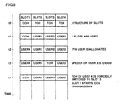
- Fig. 5 schematically shows flows in processing of allocating control channel CCH as a traffic channel (processing of the above-described first embodiment) and processing of returning communication of the control channel (unique processing of the second embodiment).
- a vertical axis indicates time and a horizontal axis indicates a structure of slots within one frame such as slots for down-link communication.
- a top slot 1 is allocated to control channel CCH, and the remaining slots 2-4 are allocated to traffic channels TCHs.
- slot 1 which was used for communication of the control channel, is then allocated for a speech signal of user 4 at time t2.
- Base station 1000 then directs user 4 using slot 1 to switch the channel at time t4, and user 4 starts a speech in the emptied slot 3.
- base station 1000 resumes communication of the control channel using slot 1, based on the traffic slot number of the control channel and transmission timing of the control channel which was transmitted by base station 1000 itself, which information was stored in store unit 60 when slot 1 for the control channel was allocated to user 4 at time t2.
- Fig. 6 is a schematic diagram showing transmission timing of the control channel.
- base station 1000 performs transmission in the control channel in a cycle of 20 frames (100 msec), for example, in PHS system.
- a user of base station 1000 can obtain information about a possibility to receive the service, such as information of radio wave intensity, from a signal of the control channel transmitted once in every cycle.
- a plurality of base stations are arranged around base station 1000, and these peripheral base stations also transmit signals of control channels CCHs.
- base station 1000 and peripheral base stations synchronize with each other, and each transmits the signal of control channel CCH in inherent timing for each base station within one cycle of control channel shown in Fig. 6 .
- base station 1000 was transmitting a signal of control channel CCH in timing TMi within one cycle of the control channel before the control channel is allocated to the traffic channel.
- base station 1000 When a traffic channel becomes empty and the transmission of the control channel is resumed, base station 1000 detects transmission timing such as TM1 of a peripheral base station with which base station 1000 was synchronizing for the transmission of the control channel as described above and, in principle, finds out from the detected transmission timing the transmission timing of control channel CCH which was previously transmitted by base station 1000, to resume the transmission of the signal of the control channel in the thus found previous transmission timing.
- transmission timing such as TM1 of a peripheral base station with which base station 1000 was synchronizing for the transmission of the control channel as described above and, in principle, finds out from the detected transmission timing the transmission timing of control channel CCH which was previously transmitted by base station 1000, to resume the transmission of the signal of the control channel in the thus found previous transmission timing.
- Fig. 7 is a flow chart showing processing of resuming transmission of the signal of the control channel shown in Fig. 5 in more detail.
- base station 1000 when a slot other than the slot for previously-used control channel (slot 3) becomes empty at time t3, base station 1000 directs a terminal PS of user 4 using the slot originally for the control channel (slot 1) to switch traffic channel TCH.
- a synchronous burst signal is transmitted to the base station using the specified traffic slot 3, and the base station also transmits the synchronous burst signal to the terminal to complete the establishment of synchronization.
- user 4 communicates with base station 1000 using the newly established traffic channel.
- base station 1000 transmission of the signal of the control channel is resumed based on information of the previously transmitted control channel.
- the resume processing is performed using information for the state (reception level, reception timing) of the signal of control channel CCH of a peripheral base station and data such as the traffic slot number of the control channel and transmission timing of the control channel, which are stored in store unit 60.
- reception level sensing unit 50 senses that the state of a peripheral base station has changed such that, for example, a signal of a control channel from the previously synchronized base station cannot be received, or there is a new peripheral base station from which a signal of a control channel is received.
- base station 1000 performs processing to synchronize with the peripheral base station again based on the state (reception level, reception timing) of the signal of control channel CCH of the peripheral base station, which state is stored in store unit 60, and then resumes transmission of the signal of control channel CCH in inherent timing for base station 1000 within one cycle of the control channel.
- Fig. 8 is a flow chart showing operations executed by control unit 40 and channel allocation computing unit 70 of adaptive array base station 1000 for processing of allocating the control channel to the traffic channel and processing of resuming transmission of the control channel.
- DSP digital signal processor
- channel allocation computing unit 70 of base station 1000 allocates this empty slot to a new user when there is a link channel (LCH) establishment request.
- LCH link channel
- step S200 when the processing is started while all of the three traffic channels are in use (step S200), a determination is made if a link channel establishment request exists (step S202). If the LCH establishment request is not received, rejection of link channel allocation is transmitted (step S218). If the LCH establishment request is received, however, a determination is made as to whether the traffic slot for the control channel can be used as a traffic slot (step S204). As this determination method has been described associated with the first embodiment with reference to Fig. 4 (steps S108, 112), the description thereof will not be repeated.
- channel allocation computing unit 70 transmits rejection of link channel allocation (step S218).
- control channel CCH can be allocated to the traffic channel
- transmission of control channel CCH from base station 1000 is stopped, and information that will be necessary for base station 1000 to resume the transmission of control channel CCH, such as a slot number of control channel CCH and transmission timing of a frame at the time just before the switching to the traffic channel, is stored in store unit 60.
- base station 1000 transmits allocation of the link channel to control channel CCH to the terminal which transmitted the link channel allocation request to allocate the slot of the control channel to the traffic slot (step S206).
- control unit 40 and channel allocation computing unit 70 are set to standby states while monitoring an occurrence of an empty slot (step S208).
- step S208 When an empty slot occurs (step S208), a determination is made as to whether the empty slot is the one that was previously used for transmission of the signal of the control channel (step S210).
- base station 1000 synchronizes with the peripheral base station based on information of the previously transmitted control channel to resume transmission of the signal of the control channel (step S212), and the processing is completed (step S216).
- control unit 40 and channel allocation computing unit 70 first direct terminal PS of the user using the slot originally for the control channel to switch traffic channel TCH to the empty slot, as described in Fig. 7 . Thereafter, base station 1000 synchronizes with the peripheral base station based on information of the previously transmitted control channel to resume transmission of the signal of the control channel (step S114), and the processing is completed (step S116).
- utilization efficiency of radio wave can be enhanced because the number of terminals connectable to a base station can increase without degrading service quality to a terminal other than the terminals currently connecting to the base station in a mobile communication system wherein both a traffic channel and a control channel exist within one frame.
- service of the base station can be enhanced by returning to the original channel allocation state when the number of calling terminals decreases.
- Fig. 9 is a schematic block diagram showing a configuration of an adaptive array base station 2000 according to a third embodiment of the present invention.
- adaptive array base station 2000 according to the present invention can also be applied to SDMA system which can communicate with a spatial multiple access as described above, as long as the conditions of the number of antennas and the multiplicity of spatial multiplexing are met.
- adaptive array base station 2000 includes an array antenna formed with a plurality of antennas such as antennas #1-#4.
- the number of antennas can be made larger or smaller as required.
- Antennas #1-#4 are respectively connected to a radio unit 100.
- quadrature detection unit 110 During reception, signals received at antennas #1-#4 are fed to a quadrature detection unit 110 via radio unit 100.
- quadrature detection unit 110 the each received signal is divided into an in-phase detection axis signal and a quadrature detection axis signal, and each signal is converted to a digital signal by an A/D converter (not shown).
- Each of the in-phase detection axis signal and quadrature detection axis signal is then fed to a synchronization processing unit 120, and fed to a switching unit 130 after synchronization processing is performed.
- switching unit 130 feeds the signals from antennas #1-#4 to reception directivity formation unit 140.
- switching unit 130 feeds a signal from antenna #1 out of antennas #1-#4, for example, to a reception processing unit 150, and feeds signals from antennas #2-#4 to reception directivity formation unit 140, at least for the slot which was originally for the control channel.
- reception directivity formation unit 140 a signal of each user is separated and extracted by adaptive array processing controlled by a control unit 170.
- a signal from antenna #1 is fed to reception processing unit 150, required processing is performed to this signal prior to demodulation processing of the control signal.
- the signal from reception processing unit 150 and the received signal of each user separated and extracted in reception directivity formation unit 140 are fed to demodulation unit 160. Therein, required demodulation processing and time-division processing are performed to reconstruct the original signal, and the result is output to a public network (not shown).
- control unit 170 determines whether there is an empty traffic channel or whether control channel CCH can be allocated as a traffic channel.
- a transmission signal provided from the public network (not shown) is fed to a modulation unit 180 via control unit 170, and therein required time-division processing and modulation processing are performed.
- a signal from modulation unit 180 is fed to a transmission directivity formation unit 190 and a transmission processing unit 200.
- transmission directivity formation unit 190 down-link transmission directivity is controlled to a transmission signal by the adaptive array processing.
- transmission directivity is produced to signals for four antennas #1-#4.
- transmission directivity is produced to signals for antennas #2-#4 out of four antennas #1-#4, at least for the slot which was originally for the control channel.
- transmission directivity formation unit 200 performs such production processing of transmission directivity based on a weight vector from reception directivity formation unit 140.
- Transmission processing unit 190 performs required processing to a control signal for control channel CCH prior to quadrature modulation when the slot of control channel CCH is allocated to a traffic channel.
- switching unit 210 feeds the signal from transmission directivity formation unit 190 to quadrature modulation unit 220, and the signal produced by modulating the signal from transmission directivity formation unit 190 is fed to each of four antennas #1-#4.
- switching unit 210 feeds the signal from transmission directivity formation unit 190 and the signal from transmission processing unit 200 to quadrature modulation unit 210.
- antenna #1 of four antennas #1-#4 the signal produced by modulating the signal from transmission processing unit 200 is fed.
- antennas #2-#4 the signal produced by modulating the signal from transmission directivity formation unit 190 is fed.
- directivity of transmission and reception is controlled using four antennas #1-#4 when the slot of control channel CCH is not allocated to a traffic channel, while directivity of transmission and reception is controlled using antennas #2-#4 out of four antennas #1-#4 when the slot of control channel CCH is allocated to a traffic channel.
- control channel CCH is transmitted and received between base station 2000 and a terminal within the service area with radio wave having no directivity. Therefore, there will be no problem in providing services even when control channel CCH is shifted to the traffic channel in base station 2000 and when a terminal other than the terminals currently connecting to base station 2000 is to originate a new speech, because the terminal within the service area of base station 2000 can receive the control signal.
- Fig. 10 is a block diagram showing a configuration of a part of reception directivity formation unit 140 in base station 2000 shown in Fig. 9 , which configuration corresponds to one user.
- a signal from a desired user terminal PS1 is extracted from input signals including signals from terminals PS1 and PS2 of two users based on signals from four antennas #1-#4. That is, the signal from terminal PS2 acts as an interference wave.
- Signals RX 1 -RX 4 from four antennas #1-#4 are fed to a reception directivity calculator 142 and multipliers 144.1-144.4.
- Reception directivity calculator 142 calculates weight vectors w 11 -w 41 using input signal, reference signal previously stored in a memory 148, and output of an adder 146.
- the latter subscript "1" indicates that it is a weight vector used for transmission and reception with the first user PS1.
- a signal sequence of preamble of the received signal includes a signal train of prescribed reference information.
- Reception directivity calculator 142 contrasts a reference signal (unique word signal) taken from memory 148 with the received signal sequence, and performs weight vector control (determination of weighting factor) so as to extract the signal which may contain the signal sequence corresponding to user terminal PS1.
- Multipliers 144.1-144.4 multiply input signals RX 1 -RX 4 and weight vectors w 1i -w 4i respectively, and feed the results to adder 146.
- Adder 146 adds output signals of multipliers 144.1-144.4 and outputs the result as a received signal y1(t), which signal is also fed to reception directivity calculator 262.
- a coefficient h ji represents a complex factor of the signal from the ith user received by the jth antenna
- n j (t) represents noise included in the jth received signal
- X(t) represents an input signal vector
- H i represents a received signal factor vector of the ith user
- N(t) represents a noise vector
- the adaptive array antenna multiplies weighting factors w 1i -w 4i to input signals from the respective antennas, and outputs the composite signal as received signal y1(t).
- the operation of the adaptive array to extract, for example, signal Srx 1 (t) transmitted by the first user will be as follows.
- Output signal y1(t) of the adaptive array can be expressed by multiplying input signal vector X(t) and a vector of a weight vector W 1 as follows.
- y ⁇ 1 t X t ⁇ W 1 T
- W 1 w 11 w 21 w 31 w 41 T
- weight vector W 1 is sequentially controlled by reception directivity calculator 142 by the well-known method so as to satisfy the following simultaneous equations.
- output signal y1(t) from the adaptive array is ultimately expressed as follows.
- Fig. 11 is a block diagram showing a configuration of a part of transmission directivity formation unit 190 in base station 2000 shown in Fig. 9 , which configuration corresponds to terminal PS1 of one user.
- transmission directivity formation unit 190 includes a transmission directivity calculator 192 calculating weight vectors w 11 -w 41 based on reception directivity information provided by reception directivity calculator 142, and multipliers 196.1-196.4 multiplying an output signal S TX (t) from modulation unit 180 to weight vectors w 11 -w 41 respectively and outputting the results.
- Outputs w 11 S TX (t)-w 41 S TX (t) of multipliers 196.1-196.4 are respectively fed to antennas #1-#4 after the quadrature modulation.
- respective weight vectors w 11 -w 41 fed to these multipliers are applied by copying weight vectors w 11 -w 41 calculated by reception directivity calculator 142 based on the received signals, as described in Fig. 10 .
- the values may be corrected corresponding to the moving speed or the like.
- the processing is performed assuming signal RX 1 (t) as 0 in processing of reception, and signal w 11 S TX (t) as 0 in processing of transmission.
- Fig. 12 is a flow chart showing operations for channel allocation executed by control unit 40 of adaptive array base station 2000.
- This processing can also be performed by a digital signal processor (DSP) within base station 2000, which is not shown, based on software according to the flow chart shown in Fig. 12 .
- the DSP reads a program including each step of the flow chart shown in Fig. 12 from a memory, which is not shown, and executes the same.
- This program can also be downloaded from a center, which is not shown, via a public circuit.
- step S300 after the channel allocation processing is started (step S300), a determination is made as to whether a link channel (LCH) establishment request exists (step S302). If the LCH establishment request is not received, rejection of link channel allocation is transmitted (step S310). If the LCH establishment request is received, however, a determination is made as to whether an empty traffic slot exists (step S304).
- LCH link channel
- step S308 a determination is made as to whether the control channel can be allocated to the traffic channel in current timing or the like. If the allocation is not possible, rejection of link channel allocation is transmitted (step S310).
- control channel can be allocated to the traffic channel, on the other had, switching units 130 and 210 are controlled such that the allocated traffic channel TCH is transmitted and received with antennas #2-#4 other than antenna #1 for control channel CCH (step S112).
- base station 2000 transmits allocation of the link channel to control channel CCH to the terminal which transmitted the link channel allocation request (step S314), and the processing is completed (step S320).
- n - m (n, m: natural number) antennas out of n antennas may be used to control the directivity of transmission and reception, and the remaining m antenna(s) may transmit and receive the control signal when the slot of control channel CCH is allocated to a traffic channel.
- utilization efficiency of radio wave can be enhanced without degrading service quality to a terminal other than the terminals currently calling a base station, because the number of terminals connectable to the base station can increase while maintaining a communication of a control channel in a mobile communication system wherein both a traffic channel and a control channel exist within one frame.
- the present invention is efficient in a mobile communication system wherein a plurality of terminals connect with a base station, because the number of terminals connectable to the base station can increase without degrading service quality to a terminal other than the terminals currently connecting to the base station.
Abstract
Description
- The present invention relates to an apparatus for a radio base station, and a method and a program of controlling communication channel allocation in a mobile communication system.
- In a mobile communication system (such as Personal Handyphone System: abbreviated as PHS hereinafter) rapidly developed in recent years, a base station is practically used which enables transmission and reception with directivity by performing so-called adaptive array processing using an array antenna formed with a plurality of antennas to attain a good communication quality.
- With this adaptive array processing by the array antenna, a communication system called PDMA (Path Division Multiple Access) system or SDMA (Space Division Multiple Access) system also becomes feasible wherein a spatial multiple access of wireless terminals (terminals or personal stations) of a plurality of users to a radio base station (base station or cellular station) is possible by spatially dividing a time slot of the same frequency to enhance utilization efficiency of radio wave frequency.
- According to such adaptive array technology, an up-link signal from an antenna on each user terminal is received by an array antenna on a base station, and is separated and extracted with reception directivity by the adaptive array processing. On the other hand, a down-link signal from the base station to the terminal is transmitted from the array antenna with transmission directivity to the antenna on the terminal.
- Since such adaptive array processing is a well-known technology and is described in detail in, for example, reference 1: "Chapter Three: MMSE Adaptive Array" (pp. 35-49) in "ARRAY ANTENNA NIYORU TEKIOUSHINGOUSYORI (Adaptive Signal Processing by Array Antenna)" by Nobuyoshi Kikuma (Sci Tech Press), the operating principles thereof will not be described herein.
- Document
US 5,778,318 discloses a method for allocating control channels in a radio system having base stations and subscriber stations communicating with respective ones of the base stations on control and traffic channels. To make the control channel operation more efficient and to avoid interference, traffic channels are allocated for control channel use so as to distribute the control channel operation between a greater number of channels, the channels allocated for control channel use being indicated to the subscriber stations and control channel operation is performed on the control channels allocated in a distributed manner. - In the following description, the base station performing down-link transmission directivity control for the terminal using such adaptive array processing is preferred to as "an adaptive array base station".
- As the communication system of the above-described PHS, TDMA system is adopted, wherein a frame (5 ms) consisting of respective four slots (one slot: 625 µs) for transmission and reception is used as a base unit. SDMA system uses the same frame structure. This communication system of PHS is standardized, for example, as "a second generation cordless telephone system".
-
Fig. 13 is a schematic diagram showing a structure of a signal transmitted and received between a terminal and a PHS base station. - A signal of one frame is divided into eight slots and, for example, the former four slots are used for reception while the latter four slots are used for transmission. Each slot includes 120 symbols.
- In the PHS system, a prescribed number of frames such as 20 frames, each having such a structure, form one cycle. That is, in the PHS system, one base station communicates with a terminal within its service area using a control channel once in every prescribed number of frames such as once in every 20 frames, and the terminal obtains information such as whether the terminal can make a call at the present position.
- In the frame structure shown in
Fig. 13 , a set of one slot for reception and one slot for transmission is allocated to the control channel while the remaining three sets of slots are respectively allocated to traffic channels for three users, for example, in the first frame of the 20 frames cycle. - In each of the other 19 frames, the set of slots corresponding to the control channel is kept empty, and the remaining three sets are successively allocated to the traffic channels for three users.
- During a control procedure of synchronization establishment in the PHS system, a link channel is first established by the control channel, followed by interference wave (U wave: Undesired wave) measurement processing and setting of a traffic condition with an allocated channel, and then a speech starts. Such a procedure is disclosed in detail in a standard of PHS, that is, a second generation cordless telephone system standard RCR STD-28 (issued by Association of Radio Industries and Businesses).
-
Fig. 14 shows such a traffic sequence flow of the PHS system. Brief description thereof will be given referring toFig. 14 . - First, a link channel establishment request signal (LCH establishment request signal) is transmitted from a PHS terminal to a base station using a C channel (control channel: CCH). The PHS base station detects (carrier sense) an empty channel (empty traffic channel: empty T channel) and, using the C channel, transmits to the PHS terminal a link channel allocation signal (LCH allocation signal) specifying the empty T channel.
- At the PHS terminal, a measurement (U wave measurement) is performed to determine if the specified T channel receives an interference wave signal having power equal to or higher than a certain value, based on the link channel information received from the PHS base station When the interference wave signal having power equal to or higher than the certain value is not detected, that is, when the specified T channel is not used by another PHS base station, a synchronous burst signal is transmitted to the base station using the specified T channel, and then the base station transmits the synchronous burst signal back to the terminal to complete the establishment of synchronization.
- On the other hand, when the interference wave signal having power equal to or higher than the certain value is detected, that is, when the specified T channel is used by another PHS base station, the PHS terminal repeats the control procedure by again transmitting the link channel establishment request signal.
- In the PHS system, a connection of a communication channel between a terminal and a base station is performed as such using a channel with a small interference wave which can obtain a good communication characteristic.
- When the control channel CCH is used for communication only in one frame of 20 frames cycle, for example, and is kept empty in the remaining 19 frames as described above, however, utilization efficiency of radio wave decreases. The efficiency is especially low in a condition of heavy traffic.
- Though it is possible to use slots for the control channel in the above-mentioned remaining 19 frames for speech communication, as the normal communication using the control channel is performed once in every 20 frames, communication data of the traffic channel allocated to the slot is interrupted once in every 20 frames (once in every 100 ms) in this situation. This causes noise, and thus a speech quality is degraded.
- Therefore, an object of the present invention is to provide an apparatus for a radio base station, and a method and a program of controlling communication channel allocation which can enhance the utilization efficiency of radio wave in a mobile communication system wherein a plurality of terminals are connected to a base station.
- An aspect of the present invention discloses an apparatus for a radio base station in a mobile communication system, wherein a signal transmitted and received in the mobile communication system is divided into a plurality of frames each including a control slot for transferring at least one control signal and a plurality of communication slots for information communication. The apparatus includes reception level sensing means for monitoring a signal level of a control slot from a peripheral base station, and channel allocation means for allocating the control slot for the information communication in response to a sensing result of the reception level sensing means when a connection is requested from a terminal device.
- When there is no empty communication slot of the radio base station, the channel allocation means preferably allocates the control slot for the information communication in response to a presence of at least a prescribed number of other peripheral base stations capable of receiving signals of the control slots, which presence is determined from a sensing result of the reception level sensing means.
- When there is no empty communication slot of the radio base station, the channel allocation means preferably allocates the control slot for the information communication in response to a signal level of the control slot from another peripheral base station being equal to or higher than a prescribed value, which signal level is determined from a sensing result of the reception level sensing means.
- Another aspect of the present invention discloses a communication channel allocation method in an apparatus for a radio base station in a mobile communication system, wherein a signal transmitted and received in the mobile communication system is divided into a plurality of frames each including a control slot for transferring at least one control signal and a plurality of communication slots for information communication. The method includes the steps of: monitoring a signal level of a control slot from a peripheral base station; and allocating the control slot for the information communication in response to a sensing result of reception level when a connection is requested from a terminal device.
- The allocating step preferably includes the steps of searching or an empty communication slot of the radio base station and, when there is no empty communication slot of the radio base station, allocating the control slot for the information communication in response to a presence of at least a prescribed number of other peripheral base stations capable of receiving signals of the control slots.
- The allocating step preferably includes the steps of searching for an empty communication slot of the radio base station and, when there is no empty communication slot of the radio base station, allocating the control slot for the information communication in response to a signal level of the control slot from another peripheral base station being equal to or higher than a prescribed value.
- A further aspect of the present invention discloses a communication channel allocation program in an apparatus for a radio base station in a mobile communication system, wherein a signal transmitted and received in the mobile communication system is divided into a plurality of frames each including a control slot for transferring at least one control signal and a plurality of communication slots for information communication. The program makes a computer execute the steps of: monitoring a signal level of a control slot from a peripheral base station; and allocating the control slot for the information communication in response to a sensing result of reception level when a connection is requested from a terminal device.
- The allocating step preferably includes the steps of searching for an empty communication slot of the radio base station and, when there is no empty communication slot of the radio base station, allocating the control slot for the information communication in response to a presence of at least a prescribed number of other peripheral base stations capable of receiving signals of the control slots.
- The allocating step preferably includes the steps of searching for an empty communication slot of the radio base station and, when there is no empty communication slot of the radio base station, allocating the control slot for the information communication in response to a signal level of the control slot from another peripheral base station being equal to or higher than a prescribed value.
- A further aspect of the present invention discloses an apparatus for a radio base station in a mobile communication system, wherein a signal transmitted and received in the mobile communication system is divided into a plurality of frames each including at least one control slot for transferring a control signal and a plurality of communication slots for information communication. The apparatus includes reception level sensing means for monitoring a signal level and reception timing of a control slot from a peripheral base station, channel allocation means for allocating the control slot for the information communication in response to a sensing result of the reception level sensing means when a connection is requested from a terminal device, storing means for storing the sensing result of the reception level sensing means when a connection is requested from the terminal device, and control means for resuming transmission of the control signal based on the sensing result stored in the storing means in response to an occurrence of an empty slot within the frame after the control slot is allocated for the information communication.
- When the empty slot is the control slot, the control means preferably synchronizes sending timing of a signal of the control slot with the peripheral base station based on the sensing result stored in the storing means to resume transmission of the control signal.
- When the empty slot is not the control slot, the control means preferably i) reallocates a terminal performing the information communication in the control slot to the empty slot, and ii) synchronizes sending timing of a signal of the control slot with the peripheral base station based on the sensing result stored in the storing means to resume transmission of the control signal.
- A further aspect of the present invention discloses a communication channel allocation method in an apparatus for a radio base station in a mobile, communication system, wherein a signal transmitted and received in the mobile communication system is divided into a plurality of frames each including a control slot for transferring at least one control signal and a plurality of communication slots for information communication. The method includes the steps of: monitoring a signal level and reception timing of a control slot from a peripheral base station; allocating the control slot for the information communication in response to the signal level of the control slot from the peripheral base station when a connection is requested from a terminal device; storing the signal level and the reception timing of the control slot from the peripheral base station when a connection is requested from the terminal device; and resuming transmission of the control signal based on the stored signal level and the reception timing of the control slot from the peripheral base station in response to an occurrence of an empty slot within the frame after the control slot is allocated for the information communication.
- When the empty slot is the control slot, the resuming step preferably includes the step of synchronizing sending timing of a signal of the control slot with the peripheral base station based on the stored signal level and the reception timing of the control slot from the peripheral base station to resume transmission of the control signal.
- When the empty slot is not the control slot, the resuming step preferably includes the steps of reallocating a terminal performing the information communication in the control slot to the empty slot, and synchronizing sending timing of a signal of the control slot with the peripheral base station based on the sensing result stored in the storing means to resume transmission of the control signal.
- A further aspect of the present invention discloses a communication channel allocation program in an apparatus for a radio base station in a mobile communication system, wherein a signal transmitted and received in the mobile communication system is divided into a plurality of frames each including a control slot for transferring at least one control signal and a plurality of communication slots for information communication. The program makes a computer execute the steps of: monitoring a signal level and reception timing of a control slot from a peripheral base station; allocating the control slot for the information communication in response to the signal level of the control slot from the peripheral base station when a connection is requested from a terminal device; storing the signal level and the reception timing of the control slot from the peripheral base station when a connection is requested from the terminal device; and resuming transmission of the control signal based on the stored signal level and the reception timing of the control slot from the peripheral base station in response to an occurrence of an empty slot within the frame after the control slot is allocated for the information communication.
- When the empty slot is the control slot, the resuming step preferably includes the step of synchronizing sending timing of a signal of the control slot with the peripheral base station based on the stored signal level and the reception timing of the control slot from the peripheral base station to resume transmission of the controls signal.
- When the empty slot is not the control slot, the resuming step preferably includes the steps of reallocating a terminal performing the information communication in the control slot to the empty slot, and synchronizing sending timing of a signal of the control slot with the peripheral base station based on the sensing result stored in the storing means to resume transmission of the control signal.
- A further aspect of the present invention discloses an apparatus for a radio base station in a mobile communication system, wherein a signal transmitted and received in the mobile communication system is divided into a plurality of frames each including at least one control slot for transferring a control signal and a plurality of communication slots for information communication. The apparatus includes a plurality of antennas, reception directivity control means for separating a signal from a desired terminal device by adaptive array processing based on signals from the plurality of antennas, and control means for allocating the control slot for the information communication when connections are requested from terminal devices which are equal to or larger in number than the capacity of the communication slot. When the control slot is allocated for the information communication, the reception directivity control means controls the reception directivity with a prescribed number of the plurality of antennas, and receives the control signal with the remaining antenna(s).
- It is preferable that the apparatus for radio base station further includes transmission directivity control means for producing a transmission signal having directivity for a desired terminal device by the adaptive array processing. When the control slot is allocated for the information communication, the transmission directivity control means controls transmission directivity with a prescribed number of the plurality of antennas, and transmits the control signal with the remaining antenna(s).
- A further aspect of the present invention discloses a communication channel allocation method in an apparatus for a radio base station which transmits and receives a signal having directivity with a desired terminal device by adaptive array processing based on signals from a plurality of antennas, wherein a signal transmitted and received in a mobile communication system is divided into a plurality of frames each including a control slot for transferring at least one control signal and a plurality of communication slots for information communication. The method includes the steps of: allocating the control slot for the information communication in response to a signal level of the control slot from a peripheral base station when a connection is requested from a terminal device; and controlling transmission and reception directivity with a prescribed number of the plurality of antennas while receiving the control signal with the remaining antenna(s) when the control slot is allocated for the information communication.
- A further aspect of the present invention discloses a communication channel allocation program in an apparatus for a radio base station which transmits and receives a signal having directivity with a desired terminal device by adaptive array processing based on signals from a plurality of antennas in a mobile communication system, wherein a signal transmitted and received in the mobile communication system is divided into a plurality of frames each including a control slot for transferring at least one control signal and a plurality of communication slots for information communication. The program makes a computer execute the steps of: allocating the control slot for the information communication in response to a signal level of the control slot from a peripheral base station when a connection is requested from a terminal device; and controlling transmission and reception directivity with a prescribed number of the plurality of antennas while receiving the control signal with the remaining antenna(s) when the control slot is allocated for the information communication.
-
-
Fig. 1 is a schematic block diagram showing a configuration of an adaptivearray base station 1000 according to first and second embodiments of the present invention. -
Fig. 2 is a first schematic diagram showing a state of radio waves ofbase station 1000 and peripheral base stations. -
Fig. 3 is a second schematic diagram showing a state of radio waves ofbase station 1000 and peripheral base stations. -
Fig. 4 is a flow chart showing operations executed by a channelallocation computing unit 70 of adaptivearray base station 1000. -
Fig. 5 schematically shows flows in processing of allocating a control channel as a traffic channel and processing of resuming communication of the control channel. -
Fig. 6 is a schematic diagram showing transmission timing of the control channel. -
Fig. 7 is a flow chart showing processing of resuming transmission of a signal of the control channel shown inFig. 5 in more detail. -
Fig. 8 is a flow chart showing operations executed by acontrol unit 40 and channelallocation computing unit 70. -
Fig. 9 is a schematic block diagram showing a configuration of an adaptivearray base station 2000 according to a third embodiment of the present invention. -
Fig. 10 is a block diagram showing a configuration of a part of a receptiondirectivity formation unit 140 inbase station 2000, which configuration corresponds to one user. -
Fig. 11 is a block diagram showing a configuration of a part of a transmissiondirectivity formation unit 190 inbase station 2000, which configuration corresponds to one user. -
Fig. 12 is a flow chart showing operations executed by acontrol unit 170 of adaptivearray base station 2000. -
Fig. 13 is a schematic diagram showing a structure of a signal transmitted and received between a terminal and a PHS base station. -
Fig. 14 is a diagram showing a traffic sequence flow. - A first embodiment of the present invention will now be described in detail with reference to the drawings.
-
Fig. 1 is a schematic block diagram showing a configuration of an adaptivearray base station 1000 according to the embodiment of the present invention. Thoughbase station 1000 according to the present invention is described as an adaptive array base station in the following description, the present invention is not limited to the adaptive array base station. The present invention is applicable to a base station of a mobile communication system wherein both a communication channel for information communication of a user such as a speech and a control channel for controlling, for example, a link establishment are allocated to a plurality of slots in one frame. - On the other hand, the present invention is applicable to a base station communicating in SDMA system, wherein a spatial multiple access is possible, as long as it is an adaptive array base station.
- Referring to
Fig. 1 , adaptivearray base station 1000 includes an array antenna formed with a plurality of antennas such as antennas #1-#4. - Antennas #1-#4 are respectively connected to a
radio unit 10. During reception, signals received at antennas #1-#4 are fed to areception unit 20 viaradio unit 10. Therein, various analog signal processing such as amplification, frequency conversion and so on is performed on the received signals fed toreception unit 20, and the signals are then converted to digital signals by an A/D converters (not shown). Furthermore, a signal of each user is separated and extracted inreception unit 20 by adaptive array processing controlled with acontrol unit 40. The received signal of each user which is separated and extracted is then fed to ademodulation unit 30, and required demodulation processing and time-division processing are performed to reconstruct the original signal, and then the result is output to a public network (not shown). - A reception
level sensing unit 50 receives a signal fromreception unit 20 and, as will be described below, outputs to control unit 40 a power level (reception level) of each received signal at antennas #1-#4, especially the received signal of control channel CCH from another base station. - As will be described below, when a link channel (LCH) establishment request is received from a terminal within a service area of
base station 1000, astore unit 60 receives and stores information fromcontrol unit 40 such as a slot number of control channel CCH, transmission timing of a frame and so on, which information will be necessary forbase station 1000 to resume transmission of control channel CCH after the control channel is allocated as a traffic channel (TCH). - When a link channel (LCH) establishment request is received from a terminal, a channel
allocation computing unit 70 determines whether there is an empty traffic channel and whether control channel CCH can be allocated as a traffic channel, and notifiescontrol unit 40 of the result while storing channel allocation information instore unit 60. - During transmission, on the other hand, a transmission provide from the public network (not shown) is fed to a
modulation unit 80 viacontrol unit 40. Required time-division processing and modulation processing are performed, and the result is fed to atransmission unit 90. Intransmission unit 90, down-link transmission directivity to the signal to be transmitted is controlled by adaptive array processing. The signal is converted to an analog signal by a D/A converter (not shown), and various analog signal processing necessary for radio transmission such as amplification, frequency conversion and so on is performed. - On transmission, signals from
transmission unit 90 are fed to antennas #1-#4 viaradio unit 10 and are transmitted to a desired terminal from antennas #1-#4. -
Fig. 2 is a first schematic diagram showing a state of radio waves ofbase station 1000 and peripheral base stations. - In
baste station 1000, when a link channel (LCH) establishment request is received from a terminal within a service area ofbase station 1000, the number of peripheral base stations transmitting signals of control channels CCHs at receivable level and level of individual control channel CCH received from the peripheral base station are determined. -
Fig. 2 shows, in a solid line, coverage of radio wave of a base station which is transmitting a signal of control channel CCH receivable at the position ofbase station 1000. Thus, inFig. 2 , signals of control channels CCHs from two out of five peripheral base stations are receivable at the position ofbase station 1000. -
Fig. 3 is a second schematic diagram showing a state of radio waves ofbase station 1000 and peripheral base stations. - Base stations are arranged in higher density in a heavy traffic area such as an urban area.
- Therefore, compared to
Fig. 2 , the situation may be such that, signals of control channels CCHs from, for example, four out of five peripheral base stations are receivable at the position ofbase station 1000 where base stations are arranged in higher density as shown inFig. 3 . - In such a situation, there will be no problem in providing services even when normal communication of control channel CCH is stopped in
base station 1000 and control channel CCH is shifted to traffic channel in all 20 frames, for example, and when a terminal other than the terminal currently connecting tobase station 1000 is to originate a new call, because a control signal of a control channel from another peripheral base station can be received within the service area ofbase station 1000. - On the other hand, when base stations are arranged in low density and the service areas are not overlapping much, that is, when there is no or only a few base stations around
base station 1000, the terminal to originate a new call will not be served at that position if normal communication of control channel CCH is stopped and control channel CCH is shifted to traffic channel in all of the frames inbase station 1000, because this is the same situation for that terminal as it is out of the service area. - Therefore, as will be described below, when the link channel (LCH) establishment request is received from a terminal, channel
allocation computing unit 70 ofbase station 1000 not only determines whether there is an empty traffic channel, but also determines whether control channel CCH ofbase station 1000 can be allocated as a traffic channel, based on the number of peripheral base stations transmitting receivable signals of control channels CCHs or a level of control channel CCH received from a peripheral base station. -
Fig. 4 is a flow chart showing operations executed by channelallocation computing unit 70 of adaptivearray base station 1000 for channel allocation. - This processing can also be performed by a digital signal processor. (DSP) within
base station 1000, which is not shown, based on software according to the flow chart shown inFig. 4 . The DSP reads a program including each step of the flow chart shown inFig. 4 from a memory, which is not shown, and executes the same. This program can also be downloaded from a center, which is not shown, via a public circuit. - Referring to
Fig. 4 , after the channel allocation processing is started (step S100), a determination is made as to whether a link channel (LCH) establishment request exists (step S102). If the LCH establishment request is not received, rejection of link channel allocation is transmitted (step S110). If the LCH establishment request is received, however, a determination is made as to whether an empty traffic slot exists (step S104). - If an empty traffic slot exists, an allocation of the link channel to a traffic channel (TCH) is transmitted (step S106), and the allocation processing is completed (step S120).
- On the other hand, if an empty traffic slot does not exist, a determination is made if there are at least a prescribed number of, for example, at least three peripheral base stations each transmitting a signal of control channel CCH at a receivable level (step S108). The "prescribed number" of base station is previously stored in
store unit 60. - If at least the prescribed number of peripheral base stations which meet the condition do exist, processing continues in step S112. If the prescribed number of peripheral base stations do not exist, rejection of link channel allocation is transmitted in step S110.
- The condition may be an existence of individual control channel CCH having relatively high level, at least a prescribed level, in control channels CCHs received from peripheral base stations, rather than the existence of at least a prescribed number of peripheral base stations with receivable control channel signals. If the condition is met, processing may continue in step S112, and if neither of the conditions is met, rejection of link channel allocation may be transmitted in step S110. This "prescribed level" is also previously stored in
store unit 60. - Therefore, if at least one of the conditions is met, that is, if there are many peripheral base stations with receivable signals even if the reception levels are relatively low, or if there are only a few peripheral base stations but they have signals with relatively high reception levels, then it is determined that a new terminal can be served by one of these peripheral base stations even when normal transmission of control channel CCH is stopped and control channel CCH is shifted to a traffic channel.
- When the condition in step S108 is met, a determination is made as to whether the control channel can be allocated to the traffic channel in current timing or the like (step S112). If the allocation is not possible, rejection of link channel allocation is transmitted (step S110).
- If the control channel can be allocated to the traffic channel, on the other hand, transmission of control channel CCH from
base station 1000 is stopped (step S114), and then information that will be necessary forbase station 1000 to resume the transmission of control channel CCH, such as a slot number of control channel CCH and transmission timing of a frame at the time just before the switching to the traffic channel, is stored in store unit 60 (step S116). - Thereafter,
base station 1000 transmits allocation of the link channel to control channel CCH to the terminal which transmitted the link channel allocation request (step S118), and the processing is completed (step S120). - As described above, according to the first embodiment of the present invention, utilization efficiency of radio wave can be enhanced because the number of terminals connectable to a base station can increase without degrading service quality to a terminal other than the terminals currently connecting to the base station in a mobile communication system wherein both a traffic channel and a control channel exist within one frame.
- A configuration of a second embodiment described below is such that, in addition to the stopped transmission of control channel CCH and allocation processing of traffic channel according to the first embodiment, the channel allocation form can return to the original form when an original traffic channel becomes empty thereafter.
- As
base station 1000 according to the second embodiment of the present invention has substantially the same structure asbase station 1000 in the first embodiment shown inFig. 1 , the structure thereof is not shown. Only the functionally different points are described in the following. - As described in the first embodiment, reception
level sensing unit 50 shown inFig. 1 detects a reception level of control channel CCH from another peripheral base station as well as reception timing thereof, and outputs the result to controlunit 40. - As also described in the first embodiment,
store unit 60 stores information such as a slot number of control channel CCH which is communicated bybase station 1000 itself and transmission timing of a frame. At the same time,store unit 60 receives fromcontrol unit 40 and stores information relating to a signal state of control channel CCH of a peripheral base station, such as a reception level and reception timing of control channel CCH from the peripheral base station. - When an original traffic channel becomes empty after control channel CCH is allocated as a traffic channel,
base station 1000 performs return processing as will be described below and returns to the original channel allocation state, wherein the speech signal is communicated with three sets of slots and the control signal is communicated with one set of slots within one frame. -
Fig. 5 schematically shows flows in processing of allocating control channel CCH as a traffic channel (processing of the above-described first embodiment) and processing of returning communication of the control channel (unique processing of the second embodiment). - In
Fig. 5 , a vertical axis indicates time and a horizontal axis indicates a structure of slots within one frame such as slots for down-link communication. - Referring to
Fig. 5 , at time t0, atop slot 1 is allocated to control channel CCH, and the remaining slots 2-4 are allocated to traffic channels TCHs. - At time t1 in this state, users 1-3 are respectively using slots 2-4 for calls.
- Based on a link channel establishment request from a
fourth user 4, when the condition such as a level of control channel signal from a peripheral base station is met as described referring toFig. 2 ,slot 1, which was used for communication of the control channel, is then allocated for a speech signal ofuser 4 at time t2. - Thereafter, it is assumed that a speech of
user 2 who was usingslot 3 is completed andslot 3 becomes empty at time t3. -
Base station 1000 then directsuser 4 usingslot 1 to switch the channel at time t4, anduser 4 starts a speech in the emptiedslot 3. At the same time,base station 1000 resumes communication of the controlchannel using slot 1, based on the traffic slot number of the control channel and transmission timing of the control channel which was transmitted bybase station 1000 itself, which information was stored instore unit 60 whenslot 1 for the control channel was allocated touser 4 at time t2. -
Fig. 6 is a schematic diagram showing transmission timing of the control channel. - As shown in
Fig. 6 ,base station 1000 performs transmission in the control channel in a cycle of 20 frames (100 msec), for example, in PHS system. A user ofbase station 1000 can obtain information about a possibility to receive the service, such as information of radio wave intensity, from a signal of the control channel transmitted once in every cycle. - As shown in
Fig. 2 , a plurality of base stations are arranged aroundbase station 1000, and these peripheral base stations also transmit signals of control channels CCHs. Thus,base station 1000 and peripheral base stations synchronize with each other, and each transmits the signal of control channel CCH in inherent timing for each base station within one cycle of control channel shown inFig. 6 . - In the example shown in
Fig. 6 ,base station 1000 was transmitting a signal of control channel CCH in timing TMi within one cycle of the control channel before the control channel is allocated to the traffic channel. - When a traffic channel becomes empty and the transmission of the control channel is resumed,
base station 1000 detects transmission timing such as TM1 of a peripheral base station with whichbase station 1000 was synchronizing for the transmission of the control channel as described above and, in principle, finds out from the detected transmission timing the transmission timing of control channel CCH which was previously transmitted bybase station 1000, to resume the transmission of the signal of the control channel in the thus found previous transmission timing. -
Fig. 7 is a flow chart showing processing of resuming transmission of the signal of the control channel shown inFig. 5 in more detail. - Referring to
Figs. 5 and7 , when a slot other than the slot for previously-used control channel (slot 3) becomes empty at time t3,base station 1000 directs a terminal PS ofuser 4 using the slot originally for the control channel (slot 1) to switch traffic channel TCH. - In terminal PS, a synchronous burst signal is transmitted to the base station using the specified
traffic slot 3, and the base station also transmits the synchronous burst signal to the terminal to complete the establishment of synchronization. - Thereafter,
user 4 communicates withbase station 1000 using the newly established traffic channel. - In
base station 1000, transmission of the signal of the control channel is resumed based on information of the previously transmitted control channel. The resume processing is performed using information for the state (reception level, reception timing) of the signal of control channel CCH of a peripheral base station and data such as the traffic slot number of the control channel and transmission timing of the control channel, which are stored instore unit 60. - When the transmission of the signal of the control channel is resumed, however, there may be an exceptional situation wherein reception
level sensing unit 50 senses that the state of a peripheral base station has changed such that, for example, a signal of a control channel from the previously synchronized base station cannot be received, or there is a new peripheral base station from which a signal of a control channel is received. In such a situation,base station 1000 performs processing to synchronize with the peripheral base station again based on the state (reception level, reception timing) of the signal of control channel CCH of the peripheral base station, which state is stored instore unit 60, and then resumes transmission of the signal of control channel CCH in inherent timing forbase station 1000 within one cycle of the control channel. -
Fig. 8 is a flow chart showing operations executed bycontrol unit 40 and channelallocation computing unit 70 of adaptivearray base station 1000 for processing of allocating the control channel to the traffic channel and processing of resuming transmission of the control channel. - These processings can also be performed by a digital signal processor (DSP) within
base station 1000, which is not shown, based on software according to the flow chart shown inFig. 8 . The DSP reads a program including each step of the flow chart shown inFig. 8 from a memory, which is not shown, and executes the same. This program can also be downloaded from a center, which is not shown, via a public circuit. - It is assumed that, if any of the slots for three traffic channels is empty, channel
allocation computing unit 70 ofbase station 1000 allocates this empty slot to a new user when there is a link channel (LCH) establishment request. - Referring to
Fig. 8 , on the other hand, when the processing is started while all of the three traffic channels are in use (step S200), a determination is made if a link channel establishment request exists (step S202). If the LCH establishment request is not received, rejection of link channel allocation is transmitted (step S218). If the LCH establishment request is received, however, a determination is made as to whether the traffic slot for the control channel can be used as a traffic slot (step S204). As this determination method has been described associated with the first embodiment with reference toFig. 4 (steps S108, 112), the description thereof will not be repeated. - If the allocation of the control channel to the traffic channel is not possible with current timing or the like, channel
allocation computing unit 70 transmits rejection of link channel allocation (step S218). - On the other hand, if the control channel can be allocated to the traffic channel, transmission of control channel CCH from
base station 1000 is stopped, and information that will be necessary forbase station 1000 to resume the transmission of control channel CCH, such as a slot number of control channel CCH and transmission timing of a frame at the time just before the switching to the traffic channel, is stored instore unit 60. Then,base station 1000 transmits allocation of the link channel to control channel CCH to the terminal which transmitted the link channel allocation request to allocate the slot of the control channel to the traffic slot (step S206). - Thereafter,
control unit 40 and channelallocation computing unit 70 are set to standby states while monitoring an occurrence of an empty slot (step S208). - When an empty slot occurs (step S208), a determination is made as to whether the empty slot is the one that was previously used for transmission of the signal of the control channel (step S210).
- If the empty slot was the one for the control channel signal,
base station 1000 synchronizes with the peripheral base station based on information of the previously transmitted control channel to resume transmission of the signal of the control channel (step S212), and the processing is completed (step S216). - If the empty slot was not the one for the control channel signal, on the other hand,
control unit 40 and channelallocation computing unit 70 first direct terminal PS of the user using the slot originally for the control channel to switch traffic channel TCH to the empty slot, as described inFig. 7 . Thereafter,base station 1000 synchronizes with the peripheral base station based on information of the previously transmitted control channel to resume transmission of the signal of the control channel (step S114), and the processing is completed (step S116). - As described above, according to the second embodiment of the present invention, utilization efficiency of radio wave can be enhanced because the number of terminals connectable to a base station can increase without degrading service quality to a terminal other than the terminals currently connecting to the base station in a mobile communication system wherein both a traffic channel and a control channel exist within one frame. In addition, service of the base station can be enhanced by returning to the original channel allocation state when the number of calling terminals decreases.
-
Fig. 9 is a schematic block diagram showing a configuration of an adaptivearray base station 2000 according to a third embodiment of the present invention. In the following description, adaptivearray base station 2000 according to the present invention can also be applied to SDMA system which can communicate with a spatial multiple access as described above, as long as the conditions of the number of antennas and the multiplicity of spatial multiplexing are met. - Referring to
Fig. 9 , adaptivearray base station 2000 includes an array antenna formed with a plurality of antennas such as antennas #1-#4. The number of antennas can be made larger or smaller as required. - Antennas #1-#4 are respectively connected to a
radio unit 100. - During reception, signals received at antennas #1-#4 are fed to a
quadrature detection unit 110 viaradio unit 100. Inquadrature detection unit 110, the each received signal is divided into an in-phase detection axis signal and a quadrature detection axis signal, and each signal is converted to a digital signal by an A/D converter (not shown). Each of the in-phase detection axis signal and quadrature detection axis signal is then fed to asynchronization processing unit 120, and fed to aswitching unit 130 after synchronization processing is performed. - As will be described below, when the slot of control channel CCH is not allocated to a traffic channel, switching
unit 130 feeds the signals from antennas #1-#4 to receptiondirectivity formation unit 140. When the slot of control channel CCH is allocated to a traffic channel, on the other hand, switchingunit 130 feeds a signal fromantenna # 1 out of antennas #1-#4, for example, to areception processing unit 150, and feeds signals from antennas #2-#4 to receptiondirectivity formation unit 140, at least for the slot which was originally for the control channel. - In reception
directivity formation unit 140, a signal of each user is separated and extracted by adaptive array processing controlled by acontrol unit 170. When a signal fromantenna # 1 is fed toreception processing unit 150, required processing is performed to this signal prior to demodulation processing of the control signal. - The signal from
reception processing unit 150 and the received signal of each user separated and extracted in receptiondirectivity formation unit 140 are fed todemodulation unit 160. Therein, required demodulation processing and time-division processing are performed to reconstruct the original signal, and the result is output to a public network (not shown). - When a link channel (LCH) establishment request is received from a terminal,
control unit 170 determines whether there is an empty traffic channel or whether control channel CCH can be allocated as a traffic channel. - During transmission, on the other hand, a transmission signal provided from the public network (not shown) is fed to a
modulation unit 180 viacontrol unit 170, and therein required time-division processing and modulation processing are performed. A signal frommodulation unit 180 is fed to a transmissiondirectivity formation unit 190 and atransmission processing unit 200. - In transmission
directivity formation unit 190, down-link transmission directivity is controlled to a transmission signal by the adaptive array processing. Herein, when the slot of control channel CCH is not allocated to a traffic channel, transmission directivity is produced to signals for four antennas #1-#4. When the slot of control channel CCH is allocated to a traffic channel, on the other hand, transmission directivity is produced to signals for antennas #2-#4 out of four antennas #1-#4, at least for the slot which was originally for the control channel. As will be described below, transmissiondirectivity formation unit 200 performs such production processing of transmission directivity based on a weight vector from receptiondirectivity formation unit 140. -
Transmission processing unit 190 performs required processing to a control signal for control channel CCH prior to quadrature modulation when the slot of control channel CCH is allocated to a traffic channel. - When the slot of control channel CCH is not allocated to a traffic channel, switching
unit 210 feeds the signal from transmissiondirectivity formation unit 190 toquadrature modulation unit 220, and the signal produced by modulating the signal from transmissiondirectivity formation unit 190 is fed to each of four antennas #1-#4. When the slot of control channel CCH is allocated to a traffic channel, on the other hand, switchingunit 210 feeds the signal from transmissiondirectivity formation unit 190 and the signal fromtransmission processing unit 200 toquadrature modulation unit 210. Toantenna # 1 of four antennas #1-#4, the signal produced by modulating the signal fromtransmission processing unit 200 is fed. To antennas #2-#4, the signal produced by modulating the signal from transmissiondirectivity formation unit 190 is fed. - Therefore, directivity of transmission and reception is controlled using four antennas #1-#4 when the slot of control channel CCH is not allocated to a traffic channel, while directivity of transmission and reception is controlled using antennas #2-#4 out of four antennas #1-#4 when the slot of control channel CCH is allocated to a traffic channel.
- Herein, the signal of control channel CCH is transmitted and received between
base station 2000 and a terminal within the service area with radio wave having no directivity. Therefore, there will be no problem in providing services even when control channel CCH is shifted to the traffic channel inbase station 2000 and when a terminal other than the terminals currently connecting tobase station 2000 is to originate a new speech, because the terminal within the service area ofbase station 2000 can receive the control signal. -
Fig. 10 is a block diagram showing a configuration of a part of receptiondirectivity formation unit 140 inbase station 2000 shown inFig. 9 , which configuration corresponds to one user. - First, operations are described when the slot of control channel CCH is not allocated to a traffic channel and the reception directivity is controlled using four antennas #1-#4.
- In the example shown in
Fig. 10 , a signal from a desired user terminal PS1 is extracted from input signals including signals from terminals PS1 and PS2 of two users based on signals from four antennas #1-#4. That is, the signal from terminal PS2 acts as an interference wave. - Signals RX1-RX4 from four antennas #1-#4 are fed to a
reception directivity calculator 142 and multipliers 144.1-144.4. -
Reception directivity calculator 142 calculates weight vectors w11-w41 using input signal, reference signal previously stored in amemory 148, and output of anadder 146. Herein, the latter subscript "1" indicates that it is a weight vector used for transmission and reception with the first user PS1. - Thus, a signal sequence of preamble of the received signal includes a signal train of prescribed reference information.
Reception directivity calculator 142 contrasts a reference signal (unique word signal) taken frommemory 148 with the received signal sequence, and performs weight vector control (determination of weighting factor) so as to extract the signal which may contain the signal sequence corresponding to user terminal PS1. - Multipliers 144.1-144.4 multiply input signals RX1-RX4 and weight vectors w1i-w4i respectively, and feed the results to adder 146.
Adder 146 adds output signals of multipliers 144.1-144.4 and outputs the result as a received signal y1(t), which signal is also fed to reception directivity calculator 262. - The signal fed to reception
directivity formation unit 140 from each antenna is expressed as follows:


- Further, a coefficient hji represents a complex factor of the signal from the ith user received by the jth antenna, and nj(t) represents noise included in the jth received signal.
- The above equations (1) to (4) are expressed in vector forms as follows.


- In the above equations (6) to (8), [...]T shows transposition of [...].
- Herein, X(t) represents an input signal vector, Hi represents a received signal factor vector of the ith user, and N(t) represents a noise vector.
- As shown in
Fig. 10 , the adaptive array antenna multiplies weighting factors w1i-w4i to input signals from the respective antennas, and outputs the composite signal as received signal y1(t). - With the preparation as described above, the operation of the adaptive array to extract, for example, signal Srx1(t) transmitted by the first user will be as follows.
- Output signal y1(t) of the adaptive array can be expressed by multiplying input signal vector X(t) and a vector of a weight vector W1 as follows.


- That is, weight vector W1 has the weighting factor wj1 (j = 1, 2, 3, 4), which is multiplied to the jth input signal RXj(t), as its element.
- Substitution of input signal vector X(t) expressed by the equation (5) into y1(t) expressed as the equation (9) gives the following equation.

- When the adaptive array ideally operates, weight vector W1 is sequentially controlled by
reception directivity calculator 142 by the well-known method so as to satisfy the following simultaneous equations.

- When weight vector W1 is completely controlled to satisfy the equations (12) and (13), output signal y1(t) from the adaptive array is ultimately expressed as follows.


- Therefore, signal Srx1(t) transmitted from the first one of the two users is obtained in output signal y1(t).
-
Fig. 11 is a block diagram showing a configuration of a part of transmissiondirectivity formation unit 190 inbase station 2000 shown inFig. 9 , which configuration corresponds to terminal PS1 of one user. - Referring to
Fig. 11 , transmissiondirectivity formation unit 190 includes atransmission directivity calculator 192 calculating weight vectors w11-w41 based on reception directivity information provided byreception directivity calculator 142, and multipliers 196.1-196.4 multiplying an output signal STX(t) frommodulation unit 180 to weight vectors w11-w41 respectively and outputting the results. Outputs w11STX(t)-w41STX(t) of multipliers 196.1-196.4 are respectively fed to antennas #1-#4 after the quadrature modulation. - In principle, respective weight vectors w11-w41 fed to these multipliers are applied by copying weight vectors w11-w41 calculated by
reception directivity calculator 142 based on the received signals, as described inFig. 10 . When it is detected that user terminal PS1 is moving, for example, the values may be corrected corresponding to the moving speed or the like. - With the processing as described above, transmission and reception of a signal having directivity with terminal PS1 becomes possible.
- Furthermore, when the slot of control channel CCH is allocated to a traffic channel and the reception directivity is controlled using three antennas #2-#4, the processing is performed assuming signal RX1(t) as 0 in processing of reception, and signal w11STX(t) as 0 in processing of transmission.
-
Fig. 12 is a flow chart showing operations for channel allocation executed bycontrol unit 40 of adaptivearray base station 2000. - This processing can also be performed by a digital signal processor (DSP) within
base station 2000, which is not shown, based on software according to the flow chart shown inFig. 12 . The DSP reads a program including each step of the flow chart shown inFig. 12 from a memory, which is not shown, and executes the same. This program can also be downloaded from a center, which is not shown, via a public circuit. - Referring to
Fig. 12 , after the channel allocation processing is started (step S300), a determination is made as to whether a link channel (LCH) establishment request exists (step S302). If the LCH establishment request is not received, rejection of link channel allocation is transmitted (step S310). If the LCH establishment request is received, however, a determination is made as to whether an empty traffic slot exists (step S304). - If an empty traffic slot exists, an allocation of the link channel to traffic channel (TCH) is transmitted (step S306), and the allocation processing is completed (step S320).
- On the other hand, if an empty traffic slot does not exist, then a determination is made as to whether the control channel can be allocated to the traffic channel in current timing or the like (step S308). If the allocation is not possible, rejection of link channel allocation is transmitted (step S310).
- If the control channel can be allocated to the traffic channel, on the other had, switching
units antenna # 1 for control channel CCH (step S112). - Thereafter,
base station 2000 transmits allocation of the link channel to control channel CCH to the terminal which transmitted the link channel allocation request (step S314), and the processing is completed (step S320). - In the description above, three of the four antennas are used to control the directivity of transmission and reception, and the remaining one antenna transmits and receives the control signal when the slot of control channel CCH is allocated to a traffic channel. More generally, (n - m) (n, m: natural number) antennas out of n antennas may be used to control the directivity of transmission and reception, and the remaining m antenna(s) may transmit and receive the control signal when the slot of control channel CCH is allocated to a traffic channel.
- As described above, according to the third embodiment of the present invention, utilization efficiency of radio wave can be enhanced without degrading service quality to a terminal other than the terminals currently calling a base station, because the number of terminals connectable to the base station can increase while maintaining a communication of a control channel in a mobile communication system wherein both a traffic channel and a control channel exist within one frame.
- The present invention is efficient in a mobile communication system wherein a plurality of terminals connect with a base station, because the number of terminals connectable to the base station can increase without degrading service quality to a terminal other than the terminals currently connecting to the base station.
Claims (16)
- A radio base station (1000, 2000) for a mobile communication system comprising the radio base station and a peripheral base station, wherein a signal transmitted and received in said mobile communication system is divided into a plurality of frames each including a control slot for transferring at least one control signal and a plurality of communication slots for information communication, said radio base station being characterized by comprising.
reception level sensing means (50) configured to monitor a signal level of a first control slot from the peripheral base station; and
channel allocation means (70) configured to allocate a second control slot of the radio base station (1000, 2000) for said information communication in response to a sensing result of said reception level sensing means when a connection is requested from a terminal device. - The radio base station (1000, 2000) according to claim 1, wherein
when there is no empty communication slot of said radio base station, said channel allocation means allocates said second control slot for said information communication in response to a presence of at least a prescribed number of other peripheral base stations capable of receiving signal of said first control slot, which presence is determined from a sensing result of said reception level sensing means. - The radio base station (1000, 2000) according to claim 1, wherein
when there is no empty communication slot of said radio base station, said channel allocation means allocates said second control slot for said information communication in response to a signal level of said first control slot from another peripheral base station being equal to or higher than a prescribed value, which signal level is determined from a sensing result of said reception level sensing means. - The radio base station (1000) according to any one of claims 1 to 3, characterized by:storing means (60) for storing a sensing result of said reception level sensing means when a connection is requested from said terminal device; andcontrol means (40) for resuming transmission of said control signal based on said sensing result stored in said storing means in response to an occurrence of an empty slot within said frame after said second control slot is allocated for said information communication.
- The radio base station (1000) according to claim 4, wherein
when said empty slot is said second control slot, said control means (40) synchronizes sending timing of a signal of said first second control slot with said peripheral base station based on said sensing result stored in said storing means to resume transmission of said control signal. - The radio base station (1000) according to claim 4, wherein
when said empty slot is not said second control slot, said control means (40)i) reallocates a terminal performing said information communication in said second control slot to said empty slot, andii) synchronizes sending timing of a signal of said second control slot with said peripheral base station based on said sensing result stored in said storing means to resume transmission of said control signal. - The radio base station (2000) according to any one of claims 1 to 6, characterized by:a plurality of antennas (#1-#4);reception directivity control means (140) for separating a signal from a desired terminal device by adaptive array processing based on signals from said plurality of antennas; whereinwhen said second control slot is allocated for said information communication, said reception directivity control means controls reception directivity with a prescribed number of said plurality of antennas, and receives said control signal with the remaining antenna or antennas.
- The radio base station (2000) according to claim 7, further comprising
transmission directivity control means (190) for producing a transmission signal having directivity for a desired terminal device by adaptive array processing, wherein
when said second control slot is allocated for said information communication, said transmission directivity control means controls transmission directivity with a prescribed number of said plurality of antennas, and transmits said control signal with the remaining antenna or antennas. - A communication channel allocation method in a radio base station (1000, 2000) for a mobile communication system, wherein a signal transmitted and received in said mobile communication system is divided into a plurality of frames each including a control slot for transferring at least one control signal and a plurality of communication slots for information communication, said method being characterized by method comprising the steps of:monitoring in said radio base station (1000, 2000) a signal level of a first control slot from a peripheral base station; andallocating a second control slot of said radio base station (1000, 2000) for said information communication in response to a sensing result of reception level when a connection is requested from a terminal device.
- The communication channel allocation method according to claim 9, wherein
said allocating step includes the steps of
searching for an empty communication slot of said radio base station (1000, 2000), and
allocating said second control slot for said information communication in response to a presence of at least a prescribed number of other peripheral base stations capable of receiving signal of said first control slot when there is no empty communication slot of said radio base station. - The communication channel allocation method according to claim 9, wherein
said allocating step includes the steps of
searching for an empty communication slot of said radio base station (1000, 2000), and
allocating said second control slot for said information communication in response to a signal level of said first control slot from another peripheral base station being equal to or higher than a prescribed value when there is no empty communication slot of said radio base station. - The communication channel allocation method as claimed in any one of claims 9 to 11, said method being characterized by the steps of:storing the signal level and said reception timing of the first control slot from said peripheral base station when a connection is requested from said terminal device; andresuming transmission of said control signal based on the stored signal level and said reception timing of the first control slot from said peripheral base station in response to an occurrence of an empty slot within said frame after said second control slot is allocated for said information communication.
- The communication channel allocation method according to claim 12, wherein
when said empty slot is said second control slot, said resuming step includes the step of synchronizing sending timing of a signal of said second control slot with said peripheral base station based on the stored signal level and said reception timing of the first control slot from said peripheral base station (1000, 2000) to resume transmission of said control signal. - The communication channel allocation method according to claim 12, wherein
when said empty slot is not said second control slot, said resuming step includes the steps of reallocating a terminal performing said information communication in said second control slot to said empty slot, and
synchronizing sending timing of a signal of said second control slot with said peripheral base station based on said sensing result stored in said storing means to resume transmission of said control signal. - The communication channel allocation method according to any one of claims 9 to 14, said method being characterized by the step of:controlling transmission and reception directivity with a prescribed number of said plurality of antennas while receiving said control signal with the remaining antenna or antennas when said second control slot is allocated for said information communication.
- A communication channel allocation program in a radio base station (1000, 2000) for a mobile communication system, wherein a signal transmitted and received in said mobile communication system is divided into a plurality of frames each including a control slot for transferring at least one control signal and a plurality of communication slots for information communication, said program being characterized by making a computer execute the steps of any one of claims 9 to 15.
Applications Claiming Priority (7)
| Application Number | Priority Date | Filing Date | Title |
|---|---|---|---|
| JP2001263514 | 2001-08-31 | ||
| JP2001263514 | 2001-08-31 | ||
| JP2001283380 | 2001-09-18 | ||
| JP2001283380 | 2001-09-18 | ||
| JP2001284401 | 2001-09-19 | ||
| JP2001284401 | 2001-09-19 | ||
| PCT/JP2002/008590 WO2003021994A1 (en) | 2001-08-31 | 2002-08-26 | Radio base apparatus, communication channel allocation method, and allocation program |
Publications (4)
| Publication Number | Publication Date |
|---|---|
| EP1429571A1 EP1429571A1 (en) | 2004-06-16 |
| EP1429571A8 EP1429571A8 (en) | 2004-09-22 |
| EP1429571A4 EP1429571A4 (en) | 2010-01-06 |
| EP1429571B1 true EP1429571B1 (en) | 2011-11-16 |
Family
ID=27347411
Family Applications (1)
| Application Number | Title | Priority Date | Filing Date |
|---|---|---|---|
| EP02762865A Expired - Fee Related EP1429571B1 (en) | 2001-08-31 | 2002-08-26 | Radio base apparatus, communication channel allocation method, and allocation program |
Country Status (7)
| Country | Link |
|---|---|
| US (1) | US6975867B2 (en) |
| EP (1) | EP1429571B1 (en) |
| JP (1) | JP3877726B2 (en) |
| KR (1) | KR100605441B1 (en) |
| CN (1) | CN100525527C (en) |
| TW (1) | TW587378B (en) |
| WO (1) | WO2003021994A1 (en) |
Families Citing this family (21)
| Publication number | Priority date | Publication date | Assignee | Title |
|---|---|---|---|---|
| US7545792B2 (en) * | 2001-06-08 | 2009-06-09 | Sony Corporation | Channel allocation method, communication system, and wireless communication apparatus in wireless network |
| JP2005020400A (en) * | 2003-06-26 | 2005-01-20 | Hitachi Communication Technologies Ltd | Radio base station, radio communication system, communication control method of radio base station, and construction method of radio communication network |
| CN1312959C (en) * | 2004-08-19 | 2007-04-25 | Ut斯达康通讯有限公司 | Method for control channels distribution in PHS base station |
| US7852746B2 (en) * | 2004-08-25 | 2010-12-14 | Qualcomm Incorporated | Transmission of signaling in an OFDM-based system |
| JP4717485B2 (en) * | 2005-03-30 | 2011-07-06 | 京セラ株式会社 | Wireless communication apparatus, wireless communication system, and wireless communication method |
| US7808948B2 (en) * | 2005-03-30 | 2010-10-05 | Motorola, Inc. | Methods for informing mobile stations of control channel architectures |
| JP4602211B2 (en) * | 2005-09-29 | 2010-12-22 | 京セラ株式会社 | Base station apparatus and communication start method |
| US7664091B2 (en) * | 2005-10-03 | 2010-02-16 | Motorola, Inc. | Method and apparatus for control channel transmission and reception |
| JP4704909B2 (en) * | 2005-12-27 | 2011-06-22 | 京セラ株式会社 | Base station apparatus and control method for base station apparatus |
| US8611300B2 (en) * | 2006-01-18 | 2013-12-17 | Motorola Mobility Llc | Method and apparatus for conveying control channel information in OFDMA system |
| JP4355333B2 (en) * | 2006-09-13 | 2009-10-28 | 京セラ株式会社 | Mobile communication system, mobile station apparatus, base station apparatus, and channel allocation method |
| JP4777205B2 (en) * | 2006-09-28 | 2011-09-21 | 京セラ株式会社 | Wireless communication system, wireless communication terminal and base station |
| US20080084853A1 (en) | 2006-10-04 | 2008-04-10 | Motorola, Inc. | Radio resource assignment in control channel in wireless communication systems |
| US7778307B2 (en) * | 2006-10-04 | 2010-08-17 | Motorola, Inc. | Allocation of control channel for radio resource assignment in wireless communication systems |
| US9520981B2 (en) * | 2007-01-12 | 2016-12-13 | Nokia Technologies Oy | Method and apparatus for providing automatic control channel mapping |
| US8290077B1 (en) * | 2008-02-12 | 2012-10-16 | Marvell International Ltd. | Communication with multiple users over a single time slot using high-order modulation |
| JP2009284449A (en) * | 2008-04-24 | 2009-12-03 | Kyocera Corp | Base station and communication method |
| EP2291037A3 (en) * | 2009-08-24 | 2014-08-13 | Marvell World Trade Ltd. | Method and apparatus for improved VAMOS transmission |
| US8416740B2 (en) * | 2009-08-25 | 2013-04-09 | Marvell World Trade Ltd. | Grouping of users onto traffic channels in multiple-users-per-channel transmission schemes |
| JP5909960B2 (en) * | 2011-09-26 | 2016-04-27 | 日本電気株式会社 | In-vehicle communication device and control method for in-vehicle communication device |
| EP3332580B1 (en) * | 2015-08-05 | 2020-04-01 | Telefonaktiebolaget LM Ericsson (PUBL) | Method and network node for dynamic resource allocation for control channels |
Family Cites Families (20)
| Publication number | Priority date | Publication date | Assignee | Title |
|---|---|---|---|---|
| JPS6446334A (en) * | 1987-08-14 | 1989-02-20 | Nec Corp | System for selecting control channel of mobile radio communication system |
| US5357513A (en) * | 1990-12-06 | 1994-10-18 | Hughes Aircraft Company | Transmission power level adjustment in radio telephony |
| JPH04255123A (en) * | 1991-01-30 | 1992-09-10 | Sony Corp | Digital cordless telephone connection method |
| JP3043171B2 (en) * | 1992-02-25 | 2000-05-22 | 富士通株式会社 | Control channel monitor method |
| FI95187C (en) * | 1992-11-30 | 1995-12-27 | Nokia Telecommunications Oy | A method for measuring adjacent base stations in a TDMA radio system and a TDMA radio system |
| FI940196A (en) | 1994-01-14 | 1995-07-15 | Nokia Telecommunications Oy | Method for allocating channels in a radio system, subscriber station and a base station |
| US5491837A (en) * | 1994-03-07 | 1996-02-13 | Ericsson Inc. | Method and system for channel allocation using power control and mobile-assisted handover measurements |
| JP3271441B2 (en) * | 1994-11-01 | 2002-04-02 | 株式会社日立製作所 | Control signal transmission slot assignment method and radio base station in mobile communication system |
| JP2762983B2 (en) * | 1996-02-02 | 1998-06-11 | 日本電気株式会社 | Assigned channel control method |
| FI100495B (en) * | 1996-02-09 | 1997-12-15 | Nokia Telecommunications Oy | Investigation of the presence of a mobile station operating on a direct channel |
| JP3444114B2 (en) * | 1996-11-22 | 2003-09-08 | ソニー株式会社 | Communication method, base station and terminal device |
| FI105867B (en) * | 1997-01-30 | 2000-10-13 | Nokia Networks Oy | Channel assignment in a mobile communication system |
| JP3056135B2 (en) | 1997-07-14 | 2000-06-26 | 日本電気移動通信株式会社 | Communication channel allocation method in mobile communication system |
| EP0942615A4 (en) * | 1997-08-08 | 2006-03-22 | Mitsubishi Electric Corp | Mobile communication system |
| EP1641141B1 (en) * | 1997-12-10 | 2009-03-25 | Mitsubishi Denki Kabushiki Kaisha | Transmission power and data rate based communication control method for a mobile communication system |
| JP3039637B2 (en) * | 1998-07-10 | 2000-05-08 | 日本電気株式会社 | Radio base station apparatus and its transmission power control method |
| JP2000308124A (en) * | 1999-04-26 | 2000-11-02 | Mitsubishi Electric Corp | Control channel arranging method |
| JP3213601B2 (en) * | 1999-05-31 | 2001-10-02 | 三洋電機株式会社 | Wireless base station |
| WO2001030108A1 (en) * | 1999-10-19 | 2001-04-26 | Ericsson Inc | Methods of selecting a control channel carrier frequency and related terminals and systems |
| FI111113B (en) * | 1999-11-18 | 2003-05-30 | Nokia Corp | Dissemination of measurement data in a communication system |
-
2002
- 2002-08-26 US US10/466,315 patent/US6975867B2/en not_active Expired - Fee Related
- 2002-08-26 JP JP2003525544A patent/JP3877726B2/en not_active Expired - Fee Related
- 2002-08-26 CN CNB028057279A patent/CN100525527C/en not_active Expired - Fee Related
- 2002-08-26 EP EP02762865A patent/EP1429571B1/en not_active Expired - Fee Related
- 2002-08-26 KR KR1020037011533A patent/KR100605441B1/en not_active IP Right Cessation
- 2002-08-26 WO PCT/JP2002/008590 patent/WO2003021994A1/en active Application Filing
- 2002-08-27 TW TW091119347A patent/TW587378B/en active
Also Published As
| Publication number | Publication date |
|---|---|
| CN1500359A (en) | 2004-05-26 |
| KR100605441B1 (en) | 2006-07-28 |
| TW587378B (en) | 2004-05-11 |
| US20040082333A1 (en) | 2004-04-29 |
| JP3877726B2 (en) | 2007-02-07 |
| EP1429571A1 (en) | 2004-06-16 |
| US6975867B2 (en) | 2005-12-13 |
| CN100525527C (en) | 2009-08-05 |
| KR20030077663A (en) | 2003-10-01 |
| WO2003021994A1 (en) | 2003-03-13 |
| EP1429571A8 (en) | 2004-09-22 |
| EP1429571A4 (en) | 2010-01-06 |
| JPWO2003021994A1 (en) | 2004-12-24 |
Similar Documents
| Publication | Publication Date | Title |
|---|---|---|
| EP1429571B1 (en) | Radio base apparatus, communication channel allocation method, and allocation program | |
| AU701764B2 (en) | Spectrally efficient high capacity wireless communication systems | |
| US7356355B2 (en) | Wireless base station for reducing interference from a control signal emitted by another wireless base station | |
| JP3462826B2 (en) | Wireless base station and wireless telephone device | |
| US20060189356A1 (en) | Mobile communication terminal apparatus | |
| AU2001244690B2 (en) | Radio base station and program recorded medium | |
| JPH09215052A (en) | Space division multiple access radio communication system and method for allocating channel for the same | |
| JP2002016538A (en) | Method for communication between terminal and access point in communication system | |
| EP1496627B1 (en) | Radio device, transmission/reception directivity control method, and transmission/reception directivity control program | |
| US20010014588A1 (en) | Radio base station and mobile station | |
| JP2001148656A (en) | Radio base station | |
| WO1990003071A1 (en) | Method and system in a wide area radio communication network | |
| EP1041839B1 (en) | Transmission channel allocation method and radio apparatus using the same | |
| JPH1132030A (en) | Pdma communication method | |
| JP4163014B2 (en) | Wireless device and communication control method | |
| CN1316760C (en) | Wireless device and communication control method | |
| JP4198452B2 (en) | Radio apparatus and antenna directivity control method | |
| JP2003069473A (en) | Wireless base station, transmission power control method and transmission power control program | |
| JP3863792B2 (en) | Wireless base station, communication method, and computer program | |
| JP2004007716A (en) | Radiotelephone equipment | |
| MXPA97005417A (en) | High-capacity and spectrally efficient wireless communication systems |
Legal Events
| Date | Code | Title | Description |
|---|---|---|---|
| PUAI | Public reference made under article 153(3) epc to a published international application that has entered the european phase |
Free format text: ORIGINAL CODE: 0009012 |
|
| 17P | Request for examination filed |
Effective date: 20040325 |
|
| AK | Designated contracting states |
Kind code of ref document: A1 Designated state(s): AT BE BG CH CY CZ DE DK EE ES FI FR GB GR IE IT LI LU MC NL PT SE |
|
| AX | Request for extension of the european patent |
Extension state: AL LT LV MK RO SI |
|
| RTI1 | Title (correction) |
Free format text: RADIO BASE APPARATUS, COMMUNICATION CHANNEL ALLOCATION METHOD, AND ALLOCATION PROGRAM |
|
| A4 | Supplementary search report drawn up and despatched |
Effective date: 20091203 |
|
| REG | Reference to a national code |
Ref country code: DE Ref legal event code: 8566 |
|
| 17Q | First examination report despatched |
Effective date: 20100219 |
|
| RAP1 | Party data changed (applicant data changed or rights of an application transferred) |
Owner name: KYOCERA CORPORATION |
|
| REG | Reference to a national code |
Ref country code: DE Ref legal event code: R079 Free format text: PREVIOUS MAIN CLASS: H04Q0007360000 Ipc: H04B0007080000 |
|
| GRAP | Despatch of communication of intention to grant a patent |
Free format text: ORIGINAL CODE: EPIDOSNIGR1 |
|
| RIC1 | Information provided on ipc code assigned before grant |
Ipc: H04W 72/08 20090101ALI20110421BHEP Ipc: H04B 7/08 20060101AFI20110421BHEP |
|
| GRAS | Grant fee paid |
Free format text: ORIGINAL CODE: EPIDOSNIGR3 |
|
| GRAA | (expected) grant |
Free format text: ORIGINAL CODE: 0009210 |
|
| AK | Designated contracting states |
Kind code of ref document: B1 Designated state(s): FI FR GB SE |
|
| REG | Reference to a national code |
Ref country code: GB Ref legal event code: FG4D |
|
| PG25 | Lapsed in a contracting state [announced via postgrant information from national office to epo] |
Ref country code: SE Free format text: LAPSE BECAUSE OF FAILURE TO SUBMIT A TRANSLATION OF THE DESCRIPTION OR TO PAY THE FEE WITHIN THE PRESCRIBED TIME-LIMIT Effective date: 20111116 |
|
| PLBE | No opposition filed within time limit |
Free format text: ORIGINAL CODE: 0009261 |
|
| STAA | Information on the status of an ep patent application or granted ep patent |
Free format text: STATUS: NO OPPOSITION FILED WITHIN TIME LIMIT |
|
| 26N | No opposition filed |
Effective date: 20120817 |
|
| GBPC | Gb: european patent ceased through non-payment of renewal fee |
Effective date: 20120826 |
|
| REG | Reference to a national code |
Ref country code: FR Ref legal event code: ST Effective date: 20130430 |
|
| PG25 | Lapsed in a contracting state [announced via postgrant information from national office to epo] |
Ref country code: FI Free format text: LAPSE BECAUSE OF FAILURE TO SUBMIT A TRANSLATION OF THE DESCRIPTION OR TO PAY THE FEE WITHIN THE PRESCRIBED TIME-LIMIT Effective date: 20111116 |
|
| PG25 | Lapsed in a contracting state [announced via postgrant information from national office to epo] |
Ref country code: GB Free format text: LAPSE BECAUSE OF NON-PAYMENT OF DUE FEES Effective date: 20120826 |
|
| PG25 | Lapsed in a contracting state [announced via postgrant information from national office to epo] |
Ref country code: FR Free format text: LAPSE BECAUSE OF NON-PAYMENT OF DUE FEES Effective date: 20120831 |