EP1429505A1 - Pre-emphasis of TMDS signaling in video applications - Google Patents
Pre-emphasis of TMDS signaling in video applications Download PDFInfo
- Publication number
- EP1429505A1 EP1429505A1 EP03024384A EP03024384A EP1429505A1 EP 1429505 A1 EP1429505 A1 EP 1429505A1 EP 03024384 A EP03024384 A EP 03024384A EP 03024384 A EP03024384 A EP 03024384A EP 1429505 A1 EP1429505 A1 EP 1429505A1
- Authority
- EP
- European Patent Office
- Prior art keywords
- signal
- channel
- receiver
- coefficient
- waveform
- Prior art date
- Legal status (The legal status is an assumption and is not a legal conclusion. Google has not performed a legal analysis and makes no representation as to the accuracy of the status listed.)
- Ceased
Links
- GJWAPAVRQYYSTK-UHFFFAOYSA-N [(dimethyl-$l^{3}-silanyl)amino]-dimethylsilicon Chemical compound C[Si](C)N[Si](C)C GJWAPAVRQYYSTK-UHFFFAOYSA-N 0.000 title description 2
- 230000011664 signaling Effects 0.000 title 1
- 238000000034 method Methods 0.000 claims abstract description 47
- 230000005540 biological transmission Effects 0.000 claims abstract description 44
- 230000015556 catabolic process Effects 0.000 claims abstract description 38
- 238000006731 degradation reaction Methods 0.000 claims abstract description 38
- 238000004891 communication Methods 0.000 claims description 47
- 238000012360 testing method Methods 0.000 claims description 14
- 238000010586 diagram Methods 0.000 description 17
- 230000006870 function Effects 0.000 description 11
- 230000003111 delayed effect Effects 0.000 description 3
- 238000001228 spectrum Methods 0.000 description 3
- 238000013459 approach Methods 0.000 description 2
- 239000000835 fiber Substances 0.000 description 2
- 238000005457 optimization Methods 0.000 description 2
- 230000004044 response Effects 0.000 description 2
- 238000012549 training Methods 0.000 description 2
- 238000011161 development Methods 0.000 description 1
- 230000000694 effects Effects 0.000 description 1
- 238000004519 manufacturing process Methods 0.000 description 1
- 238000012986 modification Methods 0.000 description 1
- 230000004048 modification Effects 0.000 description 1
- 238000011160 research Methods 0.000 description 1
- 230000035945 sensitivity Effects 0.000 description 1
- 230000008054 signal transmission Effects 0.000 description 1
- 230000001131 transforming effect Effects 0.000 description 1
Images




Classifications
-
- H—ELECTRICITY
- H04—ELECTRIC COMMUNICATION TECHNIQUE
- H04W—WIRELESS COMMUNICATION NETWORKS
- H04W52/00—Power management, e.g. Transmission Power Control [TPC] or power classes
- H04W52/04—Transmission power control [TPC]
- H04W52/18—TPC being performed according to specific parameters
- H04W52/24—TPC being performed according to specific parameters using SIR [Signal to Interference Ratio] or other wireless path parameters
-
- H—ELECTRICITY
- H04—ELECTRIC COMMUNICATION TECHNIQUE
- H04L—TRANSMISSION OF DIGITAL INFORMATION, e.g. TELEGRAPHIC COMMUNICATION
- H04L27/00—Modulated-carrier systems
- H04L27/32—Carrier systems characterised by combinations of two or more of the types covered by groups H04L27/02, H04L27/10, H04L27/18 or H04L27/26
- H04L27/34—Amplitude- and phase-modulated carrier systems, e.g. quadrature-amplitude modulated carrier systems
- H04L27/36—Modulator circuits; Transmitter circuits
- H04L27/366—Arrangements for compensating undesirable properties of the transmission path between the modulator and the demodulator
- H04L27/367—Arrangements for compensating undesirable properties of the transmission path between the modulator and the demodulator using predistortion
Definitions
- This invention relates to transmitting digital video data.
- digital video data is transmitted over a two-wire interface in a "complimentary" or “differential” manner.
- a channel is used to transmit the data, where the channel comprises all electrical connections and components between the transmitter and the receiver, including but not limited to the package, pcbs, connectors, and cables. It is contemplated that the channel may distort the transmitted signal through attenuation and delay, where attenuation and delay are a function of frequency.
- This distortion may result in an eye diagram that is more closed than would be the case if no distortion were present.
- the channel and its associated distortion will vary with the configuration/implementation of the varying transmitter sources, cables and receiver systems.
- Known prior art emphasizes improving the channel to cause less distortion and improving receiver sensitivity to interpret the signal accurately in the presence of distortion. These approaches add significantly to the cost of system implementation.
- the present invention relates to a system and method for improving the waveform at a receiver. More specifically, the present invention relates to a system and method adapted to pre-emphasize at least one transmitted signal prior to transmission such that the distortion and attenuation of the channel restores the desired waveform.
- One embodiment of the present invention relates to a system and method for improving the waveform at a receiver. More specifically, the present invention relates to a system adapted to modify at least one signal in anticipation of attenuation and delay of a channel.
- the system comprises a memory adapted to store at least one coefficient that is pre-determined based at least in part on at least one expected degradation characteristic of a channel, and a pre-emphasizer (a buffer/amplifier for example) that communicates with at least the memory and the channel, and is adapted to modify the at least one signal using the at least one coefficient prior to transmission of the at least one signal over the channel, compensating for the at least one expected degradation characteristic.
- a pre-emphasizer a buffer/amplifier for example
- Another embodiment of the present invention comprises a graphics engine that communicates with at least the memory and is adapted to generate the at least one signal.
- a signal formatter communicates with at least the pre-emphasizer and is adapted to format the at least one signal.
- the transmitter comprises a user interface communicating therewith and is adapted to select the at least one coefficient.
- the at least one expected degradation characteristic comprises at least one of attenuation and delay.
- Still another embodiment of the present invention relates to a communication system adapted to display at least one signal.
- This embodiment comprises a channel and first and second communication nodes.
- the first communication node communicates with the channel and is adapted to modify the at least one signal using at least one coefficient that is predetermined based, at least in part, on at least one expected degradation characteristic prior to transmission over the channel, to compensate for the at least one expected degradation characteristic.
- the second communication node also communicates with the channel and is adapted to receive and display the at least one signal.
- the first communication node comprises a transmitter (a set-top box for example) while the second communication node comprises a receiver (a display for example).
- the first communication node may comprise at least a pre-emphasizer (a buffer/amplifier for example) adapted to modify the at least one signal using the at least one coefficient and a memory that communicates with at least the pre-emphasis or is adapted to store the at least one coefficient.
- the first communication node may comprise a graphics engine adapted to generate the at least one signal and a signal formatter that communicates with at least the graphics engine and pre-emphasizer and adapted to format the signal.
- the at least one expected degradation characteristic waveform comprises at least one of attenuation and delay.
- Yet another embodiment of the present invention relates to a method for improving a waveform at a receiver.
- This method comprises determining at least one expected degradation characteristic of a channel prior to generating a signal for transmission.
- the method further comprises modifying the generated signal based at least in part on such determination, and after modifying, transmitting the modified signal over the channel.
- Still another embodiment comprises modifying the generated signal using at least one coefficient. It is contemplated that modifying the generated signal comprises modifying a power over frequency spectrum proportional to a reciprocal of attenuation of the channel. It is also contemplated that modifying the generated signal comprises adjusting a time of transmission proportional to a difference in propagation delay of the channel. Determining the at least one expected degradation characteristic may comprise determining at least one of attenuation or delay of the channel.
- Another embodiment of the present invention relates to a method for improving a waveform at a receiver.
- This embodiment comprises determining the expected attenuation of at least one channel and generating at least one signal for transmission.
- the at least one signal is amplified to compensate for such expected attenuation and, after amplifying, the amplified signal is transmitted over the at least one channel.
- Still another embodiment of the present invention relates to a method for improving a waveform at a receiver.
- This embodiment comprises determining the expected delay of at least one channel and generating at least one signal for transmission. At least one component of the at least one signal is delayed to compensate for the expected delay of at least one other component of the at least one signal. After delaying at least one component, the at least one signal is transmitted over the at least one channel.
- Yet another embodiment of the present invention relates to a method for improving a waveform at a receiver.
- This embodiment comprises generating a test signal (a pseudo-random signal for example) for transmission over at least one channel and determining a pixel error rate of such pseudo-random signal. At least one coefficient is selected based at least in part on such pixel error rate. At least one signal is modified using the at least one coefficient and, after such modifying, the at least one modified signal is transmitted over the at least one channel.
- a test signal a pseudo-random signal for example
- Still another embodiment of the present invention relates to a method for improving a waveform at a receiver.
- This embodiment comprises generating a plurality of test signals (pseudo-random signals for example) for transmission over at least one channel and determining the pixel error rate for each of the pseudo-random signals.
- At least one coefficient is selected from a plurality of coefficients based at least in part on at least one of such pixel error rates.
- At least one signal is modified using the at least one coefficient and, after such modifying, the at least one modified signal is transmitted over the at least one channel.
- this embodiment may comprise generating the test signals using a respective one of the plurality of coefficients, wherein selecting at least one coefficient comprises selecting the coefficient whose respective signal results in the lowest pixel error rate.
- Yet another embodiment of the present invention relates to a method for improving a waveform at a receiver.
- This embodiment comprises generating at least one signal having a predetermined signal strength for transmission over at least one channel and measuring the signal strength of at least one signal at the receiver.
- the degradation of the at least one channel is determined using the predetermined signal strength and measured signal strength (determining the difference between the two for example).
- At least one coefficient is selected based at least in part on such determined degradation, and at least one signal is modified using the at least one coefficient. After modifying the at least one signal, the at least one modified signal is transmitted over the at least one channel.
- a transmitter comprises:
- said at least one expected degradation characteristic comprises at least one of attenuation and delay.
- said pre-emphasizer comprises a buffer amplifier.
- said transmitter comprises a graphics engine communicating with at least said memory and adapted to generate said at least one signal.
- said transmitter comprises a signal formatter communicating with at least said pre-emphasizer and adapted to format said at least one signal.
- said transmitter comprises a user interface communicating therewith and adapted to select said at least one coefficient.
- a communication system adapted to display at least one signal, said system comprises:
- said at least one expected degradation characteristic comprises at least one of attenuation and delay.
- said first communication node comprises a set-top box.
- said first communication node comprises a transceiver.
- said first communication node comprises at least a pre-emphasizer adapted to modify the at least one signal using said at least one coefficient.
- said pre-emphasizer comprises a buffer/amplifier.
- said first communication node comprises a memory communicating with at least said pre-emphasizer and adapted to store said at least one coefficient.
- said first communication node comprises a graphics engine adapted to generate the at least one signal.
- said first communication node comprises a signal formatter communicating with at least said graphics engine and said pre-emphasizer and adapted to format the at least one signal.
- said communication system comprises a user interface communicating with at least said first communication node.
- said second communication node comprises a receiver.
- said second communication node comprises a display device.
- a method for improving a waveform at a receiver comprising:
- said generated signal using at least one coefficient based at least in part on said expected degradation characteristic.
- said generated signal comprises modifying a power over frequency spectrum proportional to a reciprocal of attenuation of said channel.
- said generated signal comprises adjusting a time of transmission proportional to a difference in propagation delay of said channel.
- said at least one expected degradation characteristic comprises determining at least one of attenuation and delay of said channel.
- a method for improving a waveform of a receiver comprising:
- said method for improving a waveform of a receiver comprises:
- said method for improving a waveform of a receiver comprises:
- test signal comprises a pseudo-random signal.
- said method for improving a waveform of a receiver comprises:
- test signals comprises pseudo-random signals.
- each of said test signals is generated using a respective one of said plurality of coefficients, and wherein selecting at least one coefficient comprises selecting the coefficient whose respective signal results in the lowest pixel error rate.
- said method for improving a waveform of a receiver comprises:
- the signal waveform of the TMDS signal used in the transmission of digital video/graphic data from a video source to a video monitor/display/TV may be distorted by the channel.
- One embodiment of the present invention produces a clean waveform at the receiver by altering the transmitted signal in such a way that the distortion and attenuation of the channel restores the desired waveform.
- altering the transmitted signal in anticipation of the channel effects is referred to as "pre-emphasis".
- the pre-emphasis characteristics for a plurality of expected channels are predetermined.
- Fig. 1A illustrates a known Bode Plot depicting one example of attenuation as a function of frequency in a channel
- Fig. 1B illustrates a known Bode Plat of group delay as a function of frequency for the same channel, where phase is related to group delay by phase * 1/f.
- Fig. 2A illustrates another known Bode Plot depicting one example of attenuation as a function of frequency in a different channel
- Fig. 2B illustrates a known Bode Plat of group delay as a function of frequency for the same channel, where again phase is related to group delay by phase * 1/f.
- the above-described plots illustrate that attenuation and delay in a channel are functions of frequency.
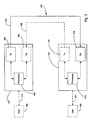
- Fig. 3 illustrates a block diagram of a generic communication system that may be employed in connection with one embodiment of the present invention.
- the system comprises a first communication node 101 (a set top box for example), a second communication node 111 (video monitor, display or TV for example), and at least one channel 109 that communicatively couples nodes 101 and 111.
- the channel 109 may include, for example, wire or fiber cabling, fiber optic cables, connecters, wireless media or any other type of communication method or device adapted to connect at least two communication nodes.
- the first communication node 101 comprises a transmitter 105 (alternatively referred to as "Tx") and a processor 106.
- the processor 106 may comprise, for example, a microprocessor.
- the first communication node 101 may, in one embodiment, communicate with a user 100 (e.g., a computer or control device) via an optional communication link 110, and generate one or more transmitted or generated signals 107 communicated via channel 109.
- a user 100 e.g., a computer or control device
- One embodiment of the present invention may include an optional receiver 103 generating one or more optional transmitted or generated signals 108 communicated to transmitter 105 via channel 109.
- the second communication node 111 comprises a receiver 114 (alternatively referred to as "Rx") and a processor 118.
- the processor 118 like processor 106, may comprise, for example, a microprocessor.
- the second communication node 111 likewise is communicatively coupled to the at least one channel 109 and adapted to receive signals 107.
- One embodiment of the present invention may include an optional transmitter 115 communicating with channel 109 and adapted to generated one or more signals 108.
- the communication node 111 may, in one embodiment, be communicatively coupled to a user 120 (again a computer or control device for example) via optional communication link 121.
- information is communicated from the first communication node 101 (a set top box for example) to the second communication node 111 (one or more video monitors, displays or TVs for example) via the at least one channel 109.
- the information is transformed in the transmitter 105 to match the restrictions imposed by the at least one channel 109.
- the transmitter 105 then communicates the information to the at least one channel 109 as one or more generated signals 107.
- the receiver 114 of the second communication node 111 receives the information from the at least one channel 109, transforming it into a form usable by communication node 111.
- channel 109 comprises an I2C channel (or similar channel) adapted to enable Tx 105 to read/write data to/from Rx 114 using a slow serial protocol for example.
- the information transmitted/received may be processed using the processors 106/118.
- the channel 109 may distort one or more of the transmitted signals through attenuation and/or delay. It is contemplated that the one or more signals may be adjusted (using pre-emphasis for example) before transmission in accordance with one embodiment of the present invention, such that the signals at the receiver 114 resemble the intended waveform, almost as if the channel had not contributed any distortion to the signals.
- pre-emphasis may comprise, but is not limited to, modifying the power over frequency spectrum proportional to the reciprocal of the channel's attenuation; adjusting the time of transmission proportional to the difference in propagation delay, but opposite in sign; or some combination of the two.
- the characteristics of the channel(s) are largely a function of cable length, although other factors such as cable manufacturer, transmitter manufacturer, the source vendor/manufacture/model and display/monitor/TV vendor/manufacturer/model, manufacturer, etc. may be considered. Improving the signal waveform at the receiver improves the pixel error rate and therefore the quality of the displayed video.
- a set of pre-emphasis coefficients and/or parameters may be predetermined for a variety of channel configurations.
- the pre-emphasis coefficients and/or parameters are selected and used to adjust the one or more signals before transmission, such that the signals at the receiver best resemble the intended waveform.
- pre-emphasis coefficients and/or parameters are selected prior to or during assembly of the communication system.
- one or more embodiments of the present invention may include an algorithm or other method or device for determining the coefficients after assembly of the communication system or prior to the transmission of the one or more signals.
- One embodiment comprises storing only one coefficient in a memory, which is used for all channel configurations.
- Another embodiment comprises storing a plurality of coefficients or parameters in a look-up table or memory, and enabling one or more users to access the look-up table or memory, selecting the optimal pre-emphasis coefficient (prior, during or after assembly of the system, or prior to the transmission of one or more signals) based upon the channel configuration.
- Another embodiment comprises training, wherein the transmitter transmits a pseudo-random data sequence.
- the transmitter coordinates with the receiver, wherein the transmitter reads the pixel error rate from the receiver and uses that information, along with an optimization algorithm to adjust the coefficients.
- the transmitter transmits a plurality of waveforms (e.g., a plurality, pseudo-random data sequences), one waveform for each of the coefficients stored in the memory.
- the transceiver coordinates with the receiver, wherein the transmitter reads the pixel-error rate for all the transmitted waveforms, and selects the coefficient that results in the lowest pixel error rate.
- the receiver may be able to determine signal degradation, and communicate such degradation to the transmitter.
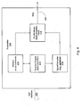
- Fig. 4 illustrates a block diagram of a transmitter system 210 in accordance with one embodiment of the present invention.
- the transmitter 210 may be contained, for example, in one or both of the communication nodes of Fig. 3, as provided previously.
- Transmitter 210 may comprise a set-top box for example, adapted to communicate with line or wire 220, where line or wire 220 may comprise a communication link or channel.
- transmitter 210 comprises a memory 212 communicating with at least graphics engine 214 and pre-emphasis buffer/amplifier 218.
- Transmitter 210 further comprises a signal formatter 216 that is adapted to communicate with graphics engine 214 and pre-emphasis buffer/amplifier 218.
- Pre-emphasis buffer/amplifier 218 is illustrated as being coupled to line or wire 220.
- An optional user interface 222 is illustrated as being coupled to the transmitter 210.
- memory 212 is adapted to store the one or more coefficients (i.e., a set of coefficients) used to pre-emphasize or adjust the one or more signals prior to transmission.
- the pre-emphasis buffer/amplifier 218 is adapted to adjust the signals using such coefficients.
- the pre-emphasis buffer/amplifier may comprise at least an amplifier having one or more variable characteristics.
- the pre-emphasis buffer/amplifier 218 adjusts the gain of the signals in accordance with the coefficients.
- the signal generator 214 is adapted to generate one or more signals or data.
- the signal generator 214 communicates with the signal formatter 216, and is adapted to reformat the signal for transmission.
- the signal formatter 216 may comprise a serializer adapted to reformat the signal in a serial format (for example, serializing 8 or 10 bits into one channel). It is also contemplated that the graphics engine 214 may generate and format the signal for transmission (i.e., eliminating the need for a separate signal formatter).
- the different channels may have the same degradation characteristics.
- only one coefficient is used for all channel configurations.
- at least one set of pre-emphasis coefficients and/or parameters may be predetermined for a variety of channel configurations.
- the pre-emphasis coefficients are selected based on the configuration of the channel prior to signal transmission as discussed below with respect to Figs. 5, 6 and 7.
- the user may access a look-up table or memory in the communication system, selecting the optimal pre-emphasis coefficient based upon the channel configuration.
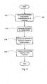
- Fig. 5 illustrates a flow diagram of one embodiment of a method, designated 300, of improving a waveform at a receiver in accordance with the present invention.
- the method comprises determining one or more expected degradation characteristics of the one or more channels as illustrated by block 310.
- Method 300 further comprises generating one or more signals for transmission as illustrated by block 312.
- the one or more signals are generated by a graphics engine in the transceiver, although other methods are contemplated.
- the one or more generated signals are modified based on the determination as illustrated by block 314. It is contemplated that the characteristics of the channel(s) are largely a function of cable length, although other factors are contemplated as provided previously. Pre-emphasis coefficients and/or parameters are selected and used to adjust the one or more generated signals before transmission, such that the signals at the receiver best resemble the intended waveform.
- the one or more modified signals are then transmitted as illustrated by block 316.
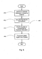
- Fig. 6 illustrates a flow diagram of another embodiment of a method, designated 400, of improving a waveform at a receiver in accordance with the present invention.
- the method comprises determining the expected attenuation caused by the one or more channels as illustrated by block 410.
- One or more signals are generated for transmission as illustrated by block 412.
- the one or more generated signals are modified based on the determination.
- the one or more signals are amplified to compensate for the expected attenuation as illustrated by block 414. It is contemplated that the one or more signals are amplified using one or more pre-emphasis coefficients and/or parameters, such that the signals best resemble the intended waveform at the receiver.
- the one or more amplified signals are then transmitted as illustrated by block 416.
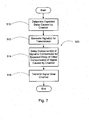
- Fig. 7 illustrates a flow diagram of yet another embodiment of a method, designated 500, of improving a waveform at a receiver in accordance with the present invention.
- method 500 comprises determining the expected delay caused by the one or more channels as illustrated by block 510.
- One or more signals are generated for transmission as illustrated by block 512. Again, the one or more generated signals are modified based on the determination. In this embodiment, the one or more signals are delayed to compensate for the expected delay as illustrated by block 514. More specifically one or more components of the signals are delayed to compensate for the expected delay of one or more of the other components of the signals caused by the channel. The one or more signals are then transmitted as illustrated by block 516.
- the transmitter transmits one or more pseudo-random data sequences and coordinates with the receiver, wherein the transmitter reads the pixel error rate from the receiver and uses that information, along with an optimization algorithm, to adjust the coefficients as discussed below with respect to Figs. 8 and 9.
- the receiver may be able to determine degradation in the one or more waveforms and communicate at least that information to the transmitter as discussed below and illustrated with respect to Fig. 10.
- Fig. 8 illustrates a flow diagram of one embodiment of a method, designated 600, of improving a waveform of a receiver in accordance with the present invention. As illustrated, the method comprises generating a pseudo-random signal for transmission over the one or more channels as illustrated by block 610.
- the receiver determines the pixel error rate for the pseudo-random signal as illustrated by block 612.
- One or more coefficients are selected based on the pixel error rate as illustrated by block 614. It is contemplated that the one or more coefficients are selected resulting in the signals best resembling the intended waveform at the receiver. It is also contemplated that a user for example selects the one or more coefficients based on such pixel error rate. However, embodiments are contemplated wherein the transmitter selects the coefficients.
- the one or more signals are modified based on such determination as illustrated by block 616. The one or more modified signals are transmitted as illustrated by block 618.
- Fig. 9 illustrates a flow diagram of another embodiment of a method, designated 700, of improving a waveform at a receiver in accordance with the present invention.
- the method comprises generating a plurality of pseudo-random signals for transmission over the one or more channels as illustrated by block 710, wherein one or more pseudo-random signal(s) is generated and transmitted for each stored coefficient and/or parameter.
- the receiver determines the pixel error rate for each of the pseudo-random signals as illustrated by block 712, transmitting such pixel error rates to the transmitter as illustrated by block 714.
- One or more coefficients are selected based on the pixel error rate as illustrated by block 716.
- the transmitter selects the one or more coefficients resulting in the signals at the receiver that best resemble the intended waveform (i.e., have the lowest pixel error rate).
- one or more signals are modified based on such determination as illustrated by block 718.
- the one or more modified signals are transmitted as illustrated by block 720.
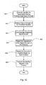
- Fig. 10 illustrates a flow diagram of another embodiment of a method, designated 800, for improving a waveform at a receiver in accordance with the present invention.
- the method comprises generating one or more signals having a predetermined signal strength for transmission over the one or more channels as illustrated by block 810.
- the signal strength of the one or more signals is measured at the receiver as illustrated by block 812, and such measured signal strength is communicated to the transmitter as illustrated by block 814.
- the transmitter determines the degradation of the signal strength of the signals, and modifies the one or more generated signals based on such determination as illustrated by blocks 816 and 818.
- the transmitter or user determines the degradation in the channel based on the difference between the predetermined signal strength and the measured signal strength.
- the transmitter selects at least one coefficient from a plurality of stored coefficients that results in the signals at the receiver best resembling the intended waveform (i.e., have the least difference between the predetermined signal strength and received signal strength).
- the one or more modified signals are transmitted as illustrated by block 820.
- HDMI High Definition Multimedia Interface
- auxiliary data during the video blanking periods.
- one or more pseudo-random or training patterns may be transmitted as auxiliary data. Because this data has a pre-defined pattern, the receiver can calculate an error rate and make this information available to the transmitter over the channel, such as a I2C channel for example. It is contemplated that it would be possible to monitor and adjust the channel performance while the channel is in use.
Landscapes
- Engineering & Computer Science (AREA)
- Computer Networks & Wireless Communication (AREA)
- Signal Processing (AREA)
- Cable Transmission Systems, Equalization Of Radio And Reduction Of Echo (AREA)
- Dc Digital Transmission (AREA)
Abstract
Description
Claims (10)
- A transmitter comprising:a memory adapted to store at least one coefficient that is predetermined based at least in part on at least one expected degradation characteristic of a channel; anda pre-emphasizer communicating with at least said memory and the channel, and adapted to modify at least one signal using said at least one coefficient prior to transmission of said at least one signal over said channel, to compensate for said at least one expected degradation characteristic.
- The transmitter of Claim 1 wherein said at least one expected degradation characteristic comprises at least one of attenuation and delay.
- The transmitter of Claim 1 wherein said pre-emphasizer comprises a buffer amplifier.
- A communication system adapted to display at least one signal comprising:a channel;a first communication node communicating with said channel and adapted to modify the at least one signal using at least one coefficient that is predetermined based at least on at least one expected degradation characteristic prior to transmission over said channel, to compensate for said at least one expected degradation characteristic; anda second communication node communicating with said channel and adapted to receive and display the at least one signal.
- A method for improving a waveform at a receiver, comprising:determining at least one expected degradation characteristic of a channel;generating a signal for transmission;modifying said generated signal based on said determination; andafter said modifying, transmitting said modified signal over the channel.
- A method for improving a waveform of a receiver, comprising:determining expected attenuation of at least one channel;generating at least one signal for transmission;amplifying said at least one signal to compensate for said expected attenuation; andafter said amplifying, transmitting said amplified signal over said at least one channel.
- A method for improving a waveform of a receiver, comprising:determining expected delay of at least one channel;generating at least one signal for transmission;delaying at least one component of said at least one signal to compensate for said expected delay of at least one other component of said at least one signal; andafter said delaying, transmitting said at least one signal over said at least one channel.
- A method for improving a waveform of a receiver, comprising:generating a test signal for transmission over at least one channel;determining a pixel error rate for said test signal;selecting at least one coefficient based at least in part on said pixel error rate;modifying at least one signal using said at least one coefficient; andafter said modifying, transmitting said at least one modified signal over said at least one channel.
- A method for improving a waveform of a receiver, comprising:generating a plurality of test signals for transmission over at least one channel;determining a pixel error rate for each of said test signals;selecting at least one coefficient from a plurality of coefficients based at least in part on at least one of said pixel error rates;modifying at least one signal using said at least one coefficient; andafter said modifying, transmitting said at least one modified signal over said at least one channel.
- A method for improving a waveform of a receiver, comprising:generating at least one signal having a predetermined signal strength for transmission over at least one channel;measuring signal strength of said at least one signal at the receiver;determining degradation of said at least one channel using said predetermined signal strength and said measured signal strength;selecting at least one coefficient based at least in part on said determined degradation;modifying at least one signal using said at least one coefficient; andafter said modifying, transmitting said at least one modified signal over said at least one channel.
Applications Claiming Priority (2)
| Application Number | Priority Date | Filing Date | Title |
|---|---|---|---|
| US316581 | 2002-12-11 | ||
| US10/316,581 US7239670B2 (en) | 2002-12-11 | 2002-12-11 | Pre-emphasis of TMDS signalling in video applications |
Publications (1)
| Publication Number | Publication Date |
|---|---|
| EP1429505A1 true EP1429505A1 (en) | 2004-06-16 |
Family
ID=32325919
Family Applications (1)
| Application Number | Title | Priority Date | Filing Date |
|---|---|---|---|
| EP03024384A Ceased EP1429505A1 (en) | 2002-12-11 | 2003-10-24 | Pre-emphasis of TMDS signaling in video applications |
Country Status (2)
| Country | Link |
|---|---|
| US (1) | US7239670B2 (en) |
| EP (1) | EP1429505A1 (en) |
Families Citing this family (7)
| Publication number | Priority date | Publication date | Assignee | Title |
|---|---|---|---|---|
| JP2005109703A (en) * | 2003-09-29 | 2005-04-21 | Pioneer Electronic Corp | Apparatus and method for outputting image, image display system, image output program and information recording medium |
| US7228154B2 (en) * | 2004-11-03 | 2007-06-05 | Sony Corporation | Method and system for processing wireless digital multimedia |
| US20060209880A1 (en) * | 2004-12-10 | 2006-09-21 | Mediatek Incorporation | Method of audio data transmission and system thereof |
| US20060160489A1 (en) * | 2005-01-14 | 2006-07-20 | Robert Hardacker | Method and system for multiple 60GHz system antennae |
| WO2007132877A1 (en) | 2006-05-16 | 2007-11-22 | Sony Corporation | Communication system, transmission device, reception device, communication method, and program |
| JP2008276067A (en) * | 2007-05-02 | 2008-11-13 | Canon Inc | Video display device and control method thereof |
| CN102282788A (en) * | 2009-01-16 | 2011-12-14 | 瑞典爱立信有限公司 | A method and an interconnecting node for use in an access network |
Citations (3)
| Publication number | Priority date | Publication date | Assignee | Title |
|---|---|---|---|---|
| EP0975124A2 (en) * | 1998-07-21 | 2000-01-26 | Nec Corporation | Radio communication system with predistortion |
| US6212229B1 (en) * | 1998-12-16 | 2001-04-03 | General Dynamics Government Systems Corporation | Adaptive pre-emphasis technique |
| WO2002027964A1 (en) * | 2000-09-29 | 2002-04-04 | Pulse-Link, Inc. | Communication system |
Family Cites Families (4)
| Publication number | Priority date | Publication date | Assignee | Title |
|---|---|---|---|---|
| JP3139312B2 (en) * | 1994-11-25 | 2001-02-26 | 株式会社富士通ゼネラル | Display driving method and apparatus |
| US5648989A (en) * | 1994-12-21 | 1997-07-15 | Paradyne Corporation | Linear prediction filter coefficient quantizer and filter set |
| US6584144B2 (en) * | 1997-02-24 | 2003-06-24 | At&T Wireless Services, Inc. | Vertical adaptive antenna array for a discrete multitone spread spectrum communications system |
| US6560459B1 (en) * | 1998-12-18 | 2003-05-06 | Nortel Networks Limited | CDMA frequency planning for fixed wireless application |
-
2002
- 2002-12-11 US US10/316,581 patent/US7239670B2/en not_active Expired - Lifetime
-
2003
- 2003-10-24 EP EP03024384A patent/EP1429505A1/en not_active Ceased
Patent Citations (3)
| Publication number | Priority date | Publication date | Assignee | Title |
|---|---|---|---|---|
| EP0975124A2 (en) * | 1998-07-21 | 2000-01-26 | Nec Corporation | Radio communication system with predistortion |
| US6212229B1 (en) * | 1998-12-16 | 2001-04-03 | General Dynamics Government Systems Corporation | Adaptive pre-emphasis technique |
| WO2002027964A1 (en) * | 2000-09-29 | 2002-04-04 | Pulse-Link, Inc. | Communication system |
Also Published As
| Publication number | Publication date |
|---|---|
| US20040125886A1 (en) | 2004-07-01 |
| US7239670B2 (en) | 2007-07-03 |
Similar Documents
| Publication | Publication Date | Title |
|---|---|---|
| CN101533379B (en) | Cable with circuitry for asserting stored cable data or other information to an external device or user | |
| CN102263575B (en) | Transmitter device, receiver device, transmission method, reception method, and transmitter/receiver device | |
| DE102013105559B4 (en) | Method of detecting a data bit depth and interface device for a display device using the same | |
| US20010036193A1 (en) | Signal transmission device and method | |
| US20070222779A1 (en) | System, method, and apparatus for content delivery format control | |
| CN101529906A (en) | Transmission method, transmission system, transmission device, and reception device | |
| US7239670B2 (en) | Pre-emphasis of TMDS signalling in video applications | |
| CN110719423B (en) | Self-adaptive HDMI cable | |
| US20090051812A1 (en) | Signal adjuster | |
| US20090201423A1 (en) | Display device, display method, supply device, supply method, storage medium, and control system | |
| KR102811309B1 (en) | Device for secure video streaming | |
| US6265951B1 (en) | Method and apparatus for equalizing channel characteristics in a computer extension system | |
| CN107947865A (en) | A kind of optical module | |
| CN101662432A (en) | Method, system and device for transmission | |
| CN210670322U (en) | DVI distributor supporting long line transmission | |
| CN106793738A (en) | The method and device of the electromagnetic interference (EMI) emissions adjustment of display device interfaces | |
| US20070052869A1 (en) | Long-distance digital visual interface (DVI) apparatus | |
| CN101651843A (en) | Device and method for generating television test signal | |
| US6147669A (en) | Method and apparatus for communicating status and control information between a processor and a display device | |
| US8035739B2 (en) | Transmission system | |
| CN105721815B (en) | HDMI conversion system and method | |
| CN101500123A (en) | Image distributor with video compensation function and compensation method thereof | |
| EP1237294B1 (en) | Method and apparatus for equalizing channel characteristics in a computer extension system | |
| US8310559B2 (en) | Method and apparatus for transmitting/receiving data | |
| KR101481564B1 (en) | Digital media receiving apparatus and method of automatically setting equalization thereof |
Legal Events
| Date | Code | Title | Description |
|---|---|---|---|
| PUAI | Public reference made under article 153(3) epc to a published international application that has entered the european phase |
Free format text: ORIGINAL CODE: 0009012 |
|
| AK | Designated contracting states |
Kind code of ref document: A1 Designated state(s): AT BE BG CH CY CZ DE DK EE ES FI FR GB GR HU IE IT LI LU MC NL PT RO SE SI SK TR |
|
| AX | Request for extension of the european patent |
Extension state: AL LT LV MK |
|
| 17P | Request for examination filed |
Effective date: 20041216 |
|
| AKX | Designation fees paid |
Designated state(s): DE FR GB |
|
| 17Q | First examination report despatched |
Effective date: 20050202 |
|
| RAP1 | Party data changed (applicant data changed or rights of an application transferred) |
Owner name: BROADCOM CORPORATION |
|
| APBN | Date of receipt of notice of appeal recorded |
Free format text: ORIGINAL CODE: EPIDOSNNOA2E |
|
| APBR | Date of receipt of statement of grounds of appeal recorded |
Free format text: ORIGINAL CODE: EPIDOSNNOA3E |
|
| APAF | Appeal reference modified |
Free format text: ORIGINAL CODE: EPIDOSCREFNE |
|
| APBT | Appeal procedure closed |
Free format text: ORIGINAL CODE: EPIDOSNNOA9E |
|
| STAA | Information on the status of an ep patent application or granted ep patent |
Free format text: STATUS: THE APPLICATION HAS BEEN REFUSED |
|
| 18R | Application refused |
Effective date: 20120508 |