EP1429432A1 - Gas laser oscillation device - Google Patents
Gas laser oscillation device Download PDFInfo
- Publication number
- EP1429432A1 EP1429432A1 EP03257749A EP03257749A EP1429432A1 EP 1429432 A1 EP1429432 A1 EP 1429432A1 EP 03257749 A EP03257749 A EP 03257749A EP 03257749 A EP03257749 A EP 03257749A EP 1429432 A1 EP1429432 A1 EP 1429432A1
- Authority
- EP
- European Patent Office
- Prior art keywords
- discharge
- sections
- discharge sections
- mode
- power
- Prior art date
- Legal status (The legal status is an assumption and is not a legal conclusion. Google has not performed a legal analysis and makes no representation as to the accuracy of the status listed.)
- Granted
Links
- 230000010355 oscillation Effects 0.000 title claims description 21
- 230000005284 excitation Effects 0.000 claims abstract description 29
- 238000010276 construction Methods 0.000 claims abstract description 10
- 230000003287 optical effect Effects 0.000 abstract description 17
- 238000000034 method Methods 0.000 description 7
- 230000003044 adaptive effect Effects 0.000 description 2
- 238000004891 communication Methods 0.000 description 2
- 230000006835 compression Effects 0.000 description 2
- 238000007906 compression Methods 0.000 description 2
- 238000005286 illumination Methods 0.000 description 2
- 238000011282 treatment Methods 0.000 description 2
- 238000012423 maintenance Methods 0.000 description 1
Images


Classifications
-
- H—ELECTRICITY
- H01—ELECTRIC ELEMENTS
- H01S—DEVICES USING THE PROCESS OF LIGHT AMPLIFICATION BY STIMULATED EMISSION OF RADIATION [LASER] TO AMPLIFY OR GENERATE LIGHT; DEVICES USING STIMULATED EMISSION OF ELECTROMAGNETIC RADIATION IN WAVE RANGES OTHER THAN OPTICAL
- H01S3/00—Lasers, i.e. devices using stimulated emission of electromagnetic radiation in the infrared, visible or ultraviolet wave range
- H01S3/02—Constructional details
- H01S3/03—Constructional details of gas laser discharge tubes
- H01S3/036—Means for obtaining or maintaining the desired gas pressure within the tube, e.g. by gettering, replenishing; Means for circulating the gas, e.g. for equalising the pressure within the tube
-
- H—ELECTRICITY
- H01—ELECTRIC ELEMENTS
- H01S—DEVICES USING THE PROCESS OF LIGHT AMPLIFICATION BY STIMULATED EMISSION OF RADIATION [LASER] TO AMPLIFY OR GENERATE LIGHT; DEVICES USING STIMULATED EMISSION OF ELECTROMAGNETIC RADIATION IN WAVE RANGES OTHER THAN OPTICAL
- H01S3/00—Lasers, i.e. devices using stimulated emission of electromagnetic radiation in the infrared, visible or ultraviolet wave range
- H01S3/05—Construction or shape of optical resonators; Accommodation of active medium therein; Shape of active medium
- H01S3/06—Construction or shape of active medium
- H01S3/07—Construction or shape of active medium consisting of a plurality of parts, e.g. segments
- H01S3/073—Gas lasers comprising separate discharge sections in one cavity, e.g. hybrid lasers
-
- H—ELECTRICITY
- H01—ELECTRIC ELEMENTS
- H01S—DEVICES USING THE PROCESS OF LIGHT AMPLIFICATION BY STIMULATED EMISSION OF RADIATION [LASER] TO AMPLIFY OR GENERATE LIGHT; DEVICES USING STIMULATED EMISSION OF ELECTROMAGNETIC RADIATION IN WAVE RANGES OTHER THAN OPTICAL
- H01S3/00—Lasers, i.e. devices using stimulated emission of electromagnetic radiation in the infrared, visible or ultraviolet wave range
- H01S3/02—Constructional details
- H01S3/03—Constructional details of gas laser discharge tubes
- H01S3/038—Electrodes, e.g. special shape, configuration or composition
- H01S3/0385—Shape
-
- H—ELECTRICITY
- H01—ELECTRIC ELEMENTS
- H01S—DEVICES USING THE PROCESS OF LIGHT AMPLIFICATION BY STIMULATED EMISSION OF RADIATION [LASER] TO AMPLIFY OR GENERATE LIGHT; DEVICES USING STIMULATED EMISSION OF ELECTROMAGNETIC RADIATION IN WAVE RANGES OTHER THAN OPTICAL
- H01S3/00—Lasers, i.e. devices using stimulated emission of electromagnetic radiation in the infrared, visible or ultraviolet wave range
- H01S3/05—Construction or shape of optical resonators; Accommodation of active medium therein; Shape of active medium
- H01S3/08—Construction or shape of optical resonators or components thereof
- H01S3/08086—Multiple-wavelength emission
Definitions
- the power sources for discharge excitation that supply discharge power to at least two discharge sections are constructed so as to be capable of adj ustment of the distribution of the amount of discharge power supplied to these at least two discharge sections.
- power sources for discharge excitation that operate mutually independently, of the same number as "these at least two discharge sections" may be employed.
- the transverse mode of the laser output may be controlled by changing the distribution of the discharge of power in respect of the respective discharge sections by controlling the discharge power supplied to the discharge sections.
- high-speed operation can easily be achieved by electrical control without depending on control of mechanical conditions such as aperture movement or change of mirror curvature, so that a gas laser oscillation device can be provided having a laser beam mode control function that is excellent in respect of controllability, convenience of handling, ease of maintenance, and economy.
- the discharge sections 2a, 2b are respectively provided with electrodes 12a, 12b.
- the electrode 12a is connected with a power source 1a for discharge excitation and the electrode 12b is connected with a power source 1b for discharge excitation.
- These power sources 1a, 1b for discharge excitation are respectively independently operated AC power sources and are arranged to be capable of being individually adjusted to set the power that is supplied to the respective discharge sections 2a, 2b. Since such AC power sources for discharge excitation are themselves well known, a detailed description of for example their circuit layouts for adjustment of the supplied power is dispensed with.
- the type of gas laser oscillation device to which the present invention is applicable includes low-speed axial flow type lasers, biaxial orthogonal type lasers, triaxial orthogonal type lasers, or TEA lasers and the like, apart from the high-speed axial flow type lasers of the embodiments described above.
- the present invention can be applied to DC discharge, pulse discharge or SD discharge type lasers, apart from the AC discharge type lasers described above. It is clear that the same benefits can be obtained by applying the present invention to gas lasers of these types also.
Landscapes
- Physics & Mathematics (AREA)
- Electromagnetism (AREA)
- Engineering & Computer Science (AREA)
- Plasma & Fusion (AREA)
- Optics & Photonics (AREA)
- Lasers (AREA)
Abstract
Description
- The present invention relates to a laser oscillation device of the discharge excitation type employing a gas as the laser medium, that is used in for example laser processing, medical treatment, illumination or communication and in particular relates to a gas laser oscillation device having a function of controlling the transverse mode of the laser output (hereinbelow referred to as "beam mode" or simply as "mode").
- Gas laser oscillation devices are widely employed in for example laser processing, medical treatment, illumination or communication and gas laser oscillation devices are known having a plurality of discharge sections, respective power sources for discharge excitation being connected to electrodes provided in each discharge section. Figure 8 is a view showing the layout of major parts of a typical example thereof. In this Figure,
reference symbols mirrors discharge sections - The
discharge sections electrodes 22a and 22b. Theelectrode 22a is connected with a power source 1a for discharge excitation and the electrode 22b is connected with apower source 1b for discharge excitation. Thedischarge sections electrodes 22a and 22b, electrodes of the same size and same shape and same electrode construction are employed. - The
power sources 1a, 1b for discharge excitation are of the commonly known type that can be respectively independently operated and wherein the power that is supplied to thedischarge sections - The laser medium gas is circulated through a circulatory path passing through the optical resonator using a
fan 6. The medium gas that is fed from the fan is supplied to thedischarge sections heat exchanger 5a to remove the heat of compression. The laser medium gas is excited by discharge in thedischarge sections output mirror 4b. After emitting the laser light, the gas medium, which has reached a high temperature due to the discharge, is cooled in aheat exchanger 5b and again returned to thefan 6. In this example, the twodischarge sections power sources 1a, 1b for discharge excitation, which are operated independently. Thepower sources 1a, 1b for discharge excitation are AC power sources, so the discharge that is created in thedischarge sections - Typically, in a gas laser oscillation device of this type, a beam mode is formed that is determined by the construction and dimensions of the optical resonator. That is, various different beam modes can be formed, depending on the length of the optical resonator (length of the optical path between the
mirrors - In fact, what sort of beam mode should be produced when employing the laser oscillation device is determined by the object, such as processing, for which this device is to be employed. However, in order to be able to cope with a wide range of applications, it is desirable that this beam mode should be capable of being suitably controlled to exhibit characteristics matching the application.
- Regarding the control of this beam mode, a method of changing the mode that is widely employed conventionally is to introduce into or remove from the optical path an aperture, as disclosed in European Patent Application Laid-open No. 0492340.
- Specifically, mode changeover is effected between the TEM00 mode (gaussian mode) or low-order mode and TEM01* (ring mode) or higher-order modes when an aperture is arranged on the optical axis or when the aperture is removed from the optical axis. However, typically, methods of mechanically moving such an aperture involve problems relating to durability or response, high-speed control thereof is difficult and adjustment of the optical axis of the aperture is also difficult, and such methods are very costly.
- A further example of disclosure of prior art is Japanese Patent Application Laid-open No. 2002-118312. This relates to improvements in a method of controlling beam mode. In the embodiment of this publication, an adaptive mirror (mirror whose curvature can be changed) is employed for mode control and a technique is illustrated of changing over the mode by setting two mechanically changeable mirror curvatures. However, even with this method in which mirror curvature is changed, problems relating to response, controllability, difficulty of optical axis adjustment and cost still arise. A detailed description of the function and construction of an adaptive mirror is to be found in Japanese Patent Number 3072519.
- According to the present invention, a gas laser oscillation device comprising a plurality of discharge sections that are respectively provided with electrodes for discharge and a plurality of power sources for discharge excitation respectively connected with the electrodes of the plurality of sections includes at least two discharge sections comprising electrodes that excite mutually different modes when respective independent discharges are produced in the plurality of discharge sections.
- Of the plurality of power sources for discharge excitation, the power sources for discharge excitation that supply discharge power to at least two discharge sections are constructed so as to be capable of adj ustment of the distribution of the amount of discharge power supplied to these at least two discharge sections. For example, power sources for discharge excitation that operate mutually independently, of the same number as "these at least two discharge sections", may be employed. In this way, the transverse mode of the laser output may be controlled by changing the distribution of the discharge of power in respect of the respective discharge sections by controlling the discharge power supplied to the discharge sections.
- As the combination of "electrodes that excite mutually different modes when respective independent discharges are produced" in the discharge sections, a combination of electrodes may be adopted wherein at least one of the dimensions, shape or construction of these electrodes is different.
- According to the present invention, use of the device in a wide range of applications can be achieved by realizing in a simple manner beam modes that are optimum for various different types of application simply by adjusting the distribution of power supplied to the discharge sections by the power sources for discharge excitation. Also, if the device is applied to a laser processing device that performs for example processing of materials, control of the beam mode becomes possible by specifying any desired position or section or time in respect of the processing head, thereby making it possible to provide a laser oscillation device of high performance.
- According to the present invention, high-speed operation can easily be achieved by electrical control without depending on control of mechanical conditions such as aperture movement or change of mirror curvature, so that a gas laser oscillation device can be provided having a laser beam mode control function that is excellent in respect of controllability, convenience of handling, ease of maintenance, and economy.
- Objects and features in addition to the objects and features of the present invention as described above will become clear from the following description of an embodiment thereof with reference to the appended drawings. In the drawings:
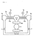
- Figure 1 is a view showing the layout of major parts of a laser oscillation device according to an embodiment of the present invention;
- Figure 2A is a cross-sectional view given in explanation of a discharge tube
employed in a
discharge section 2a and Figure 2B is a view showing the mode that is excited when discharge is produced independently in thedischarge section 2a; - Figure 3A is a cross-sectional view given in explanation of a discharge tube
employed in a
discharge section 2b and Figure 3B is a view showing the mode that is excited when discharge is produced independently in thedischarge section 2b; - Figure 4 is a view showing the mode that is excited when substantially the same
power is supplied to the
discharge sections - Figure 5 is a view showing the mode that is excited when power supply to the
discharge section 2a is made somewhat larger and power supply to thedischarge section 2b is made somewhat smaller; - Figure 6 is a view showing the mode that is excited when power supply to the
discharge section 2a is made somewhat smaller and power supply to thedischarge section 2b is made somewhat larger; - Figure 7A is a view showing the layout of major parts of a laser oscillation device
according to one embodiment of the present invention, Figure 7B is a view showing the
mode obtained when substantially equal power supply is effected to
discharge sections discharge section 2d, and Figure 7D is a view showing the mode that is obtained when power supply is effected solely to thedischarge section 2c, respectively; and - Figure 8 is a view given in explanation of the layout of major parts in respect of a prior art example of a gas laser oscillation device having a plurality of discharge sections and wherein power sources for discharge excitation are respectively connected to electrodes provided in the discharge sections.
-
- Figure 1 is a view showing the layout of major parts of a laser oscillation device according to one embodiment of the present invention, shown with the same mode of representation as in Figure 8. The same reference numerals are employed as appropriate for elements that are common with the layout shown in Figure 8. Referring to this Figure, an optical resonance space is formed between the
rear mirror 4a, which does not have partial transparency, and theoutput mirror 4b, which has partial transparency, and twodischarge sections - The
discharge sections electrodes electrode 12a is connected with a power source 1a for discharge excitation and theelectrode 12b is connected with apower source 1b for discharge excitation. Thesepower sources 1a, 1b for discharge excitation are respectively independently operated AC power sources and are arranged to be capable of being individually adjusted to set the power that is supplied to therespective discharge sections - In the same way as in the example shown in Figure 8, the laser medium gas is circulated through a circulatory path passing through the optical resonator, by means of a
fan 6. The medium gas that is delivered by the fan passes through aheat exchanger 5a for removing the heat of compression and is supplied to thedischarge sections discharge sections output mirror 4b. - After emission of laser light, the medium gas that has been heated to a high temperature by the discharge is cooled in a
heat exchanger 5b, before being returned again to thefan 6. The twodischarge sections power sources 1a, 1b for discharge excitation, that are independently operated. - What is important here is that, in contrast to the prior art example shown in Figure 8, the shape of the electrodes of the discharge tubes constituting the
discharge sections discharge section 2a, as shown in Figure 2A, there is provided anelectrode 12a having a narrow electrode width whereas in the discharge tube of thedischarge section 2b, as shown in Figure 3A, there is provided anelectrode 12b having a broader electrode width. - As disclosed in Japanese Patent Application Laid-open No. 64-42187 mentioned above, the mode that is excited changes depending on the width of the electrode of the discharge tube. In this embodiment, when discharge is effected solely in the
discharge section 2a, which is of narrow electrode width, (i.e. thepower source 1b for discharge excitation is OFF), a mode similar to the gaussian mode as shown in Figure 2B is obtained while, when discharge is effected solely in thedischarge section 2b, which is of broader electrode width, (i.e. the power source 1a for discharge excitation is OFF), as shown in Figure 3B, the ring mode is obtained. - If discharge is produced in both of the
discharge sections discharge sections - Also, if the power supply to the
discharge section 2a is made larger while the power supply to thedischarge section 2b is made smaller, a mode as shown in Figure 5 is obtained while if the power supply to thedischarge section 2b is made larger and the power supply to thedischarge section 2a is made smaller, a mode as shown in Figure 6 is obtained. In this way, a mode suited to the application can be set by adjusting the distribution of power supplied to thedischarge sections - It should be noted that, although, in this embodiment, an example was described in which
electrodes discharge sections - That is, if the mode that is obtained when discharge is performed independently in the
discharge section 2a is designated as mode A and the mode that is obtained when discharge is performed independently in thedischarge section 2b is designated as mode B, all the intermediate modes of mode A and mode B can be freely selected. - In order to satisfy the condition regarding the combination of specifications of the above discharge sections, namely, that "when discharge is produced independently in the discharge sections having the respective electrodes, mutually different modes are excited", in general, it suffices if at least one of the "electrode shape", "electrode size (area)", "electrode structure", "shape of the discharge section itself" or "size (for example, diameter) of the discharge section itself" is made different.
- Figure 7A is a view with the same mode of representation as in Figure 1 of an embodiment in which two discharge sections having mutually different diameters are combined. The laser oscillation device shown in Figure 7A has the same construction as that shown in Figure 1 apart from the use of
discharge sections discharge sections - In this case, if substantially the same power is supplied to the
discharge sections discharge section 2d and Figure 7D shows a mode of double-peak shape obtained if power is supplied only to thedischarge section 2c. Above from this, various modes obtained by mixing Figure 7C and Figure 7D can be obtained by various choices of the ratio of power supply by thevariable power sources 1a, 1b for discharge excitation. A mode suited to a particular application can therefore easily be set. - Also, as another example in which the discharge electrodes are made different from each other, helical electrodes may be employed for the two discharge sections, the pitch of the helices being different. Another effective method is to provide a slit in the middle of one of the electrode widths (example of different construction).
- Furthermore, even if the number of discharge sections provided in the optical resonator is three or more, so long as it is possible to control distribution of the supply of discharge power to each discharge section in respect of at least two discharge sections of these discharge sections and the electrodes are selected such that "different modes are excited when discharge is effected independently", a gas laser oscillation device whose mode can be controlled can of course be obtained just as in the case of the embodiments described above.
- For example, two "discharge sections (using identical electrodes) whereby mode A is obtained in the case of independent discharge" having identical electrodes may be provided, these discharge sections being driven with a single power source for discharge excitation, and, in addition, there may be provided a single "discharge section whereby mode B is obtained in the case of independent discharge" having a separate electrode, between these two discharge sections, this single discharge section being driven with a single separate power source for discharge excitation. Variable control of the mode that is obtained from the laser oscillation device as a whole can then be achieved by adjusting the amount of discharge power that is supplied from the independently operated power sources for discharge excitation.
- It should be noted that the type of gas laser oscillation device to which the present invention is applicable includes low-speed axial flow type lasers, biaxial orthogonal type lasers, triaxial orthogonal type lasers, or TEA lasers and the like, apart from the high-speed axial flow type lasers of the embodiments described above. Also, regarding the type of discharge, the present invention can be applied to DC discharge, pulse discharge or SD discharge type lasers, apart from the AC discharge type lasers described above. It is clear that the same benefits can be obtained by applying the present invention to gas lasers of these types also.
- As described above, according to the present invention, a beam mode control function can be realized that is convenient and straightforward and of excellent controllability, so that the optimum beam mode for various applications can be set in a simple fashion, making it possible to apply the present invention to a wide range of applications. Also, when applied to a laser processing device, beam mode control can be achieved at any desired position or time during processing, thereby providing a laser processing device of excellent functionality.
Claims (3)
- A gas laser oscillation device, comprising a plurality of discharge sections that are respectively provided with electrodes for discharge and a plurality of power sources for discharge excitation that supply discharge power to the discharge sections and are respectively connected with the electrodes of the plurality of discharge sections,
wherein said plurality of discharge sections include at least two discharge sections in which mutually different beam modes are excited when respective independent discharges are produced; and
of said plurality of power sources for discharge excitation, the power sources for discharge excitation that supply discharge power to at least two discharge sections can adjust the distribution of the amount of discharge power supplied to these at least two discharge sections. - The gas laser oscillation device according to claim 1 wherein, in the combination of said discharge sections, the electrodes that are respectively provided in the discharge sections differ in regard to at least one of dimensions, shape or construction.
- The gas laser oscillation device according to claim 1 wherein, in the combination of said discharge sections, the discharge sections differ in regard to at least one of dimensions or shape.
Priority Applications (1)
| Application Number | Priority Date | Filing Date | Title |
|---|---|---|---|
| DE60305136T DE60305136T3 (en) | 2002-12-10 | 2003-12-10 | Gas laser oscillation device |
Applications Claiming Priority (2)
| Application Number | Priority Date | Filing Date | Title |
|---|---|---|---|
| JP2002358027 | 2002-12-10 | ||
| JP2002358027A JP3787120B2 (en) | 2002-12-10 | 2002-12-10 | Gas laser oscillator |
Publications (3)
| Publication Number | Publication Date |
|---|---|
| EP1429432A1 true EP1429432A1 (en) | 2004-06-16 |
| EP1429432B1 EP1429432B1 (en) | 2006-05-10 |
| EP1429432B2 EP1429432B2 (en) | 2012-11-28 |
Family
ID=32322075
Family Applications (1)
| Application Number | Title | Priority Date | Filing Date |
|---|---|---|---|
| EP03257749A Expired - Lifetime EP1429432B2 (en) | 2002-12-10 | 2003-12-10 | Gas laser oscillation device |
Country Status (4)
| Country | Link |
|---|---|
| US (1) | US7173954B2 (en) |
| EP (1) | EP1429432B2 (en) |
| JP (1) | JP3787120B2 (en) |
| DE (1) | DE60305136T3 (en) |
Families Citing this family (4)
| Publication number | Priority date | Publication date | Assignee | Title |
|---|---|---|---|---|
| JP4012216B2 (en) * | 2005-06-08 | 2007-11-21 | ファナック株式会社 | Laser oscillator |
| US20080285613A1 (en) * | 2007-05-17 | 2008-11-20 | Synrad, Inc. | Colpitts rf power oscillator for a gas discharge laser |
| DE112011103110B4 (en) * | 2010-09-17 | 2016-12-01 | Mitsubishi Electric Corporation | Gas laser device |
| KR20260013191A (en) * | 2023-05-22 | 2026-01-27 | 에이에스엠엘 네델란즈 비.브이. | Optical amplifier and device therefor |
Citations (7)
| Publication number | Priority date | Publication date | Assignee | Title |
|---|---|---|---|---|
| US4622675A (en) * | 1983-07-29 | 1986-11-11 | P.R.C., Ltd. | Forced transport molecular gas laser and method |
| US4677637A (en) * | 1980-11-22 | 1987-06-30 | Heinrich Karning | TE laser amplifier |
| US4757511A (en) * | 1984-11-24 | 1988-07-12 | Trumpf Gmbh & Company | High frequency folded gross-flow gas laser with approved gas flow characteristics and method for producing laser beam using same |
| US5422906A (en) * | 1992-11-18 | 1995-06-06 | Matsushita Electric Industrial Co., Ltd. | Laser resonator |
| US5426659A (en) * | 1992-12-28 | 1995-06-20 | Matsushita Electric Industrial Co., Ltd. | Axial flow type laser oscillator |
| US5450435A (en) * | 1992-09-14 | 1995-09-12 | Matsushita Electric Industrial Co., Ltd. | Gas laser oscillator |
| EP1184946A1 (en) * | 2000-08-31 | 2002-03-06 | TRUMPF LASERTECHNIK GmbH | Gaslaser |
Family Cites Families (6)
| Publication number | Priority date | Publication date | Assignee | Title |
|---|---|---|---|---|
| JPS61280689A (en) * | 1985-06-05 | 1986-12-11 | Mitsubishi Electric Corp | Gas laser apparatus |
| JPS6442187U (en) | 1987-09-09 | 1989-03-14 | ||
| JPH02281670A (en) * | 1989-04-21 | 1990-11-19 | Matsushita Electric Ind Co Ltd | High frequency excitation gas laser oscillation device |
| JPH02281669A (en) | 1989-04-21 | 1990-11-19 | Matsushita Electric Ind Co Ltd | Direct current excitation gas laser oscillation device |
| DE4041815A1 (en) | 1990-12-24 | 1992-06-25 | Trumpf Lasertechnik Gmbh | GAS LASER WITH AN ADJUSTING DEVICE FOR A MACHINE PART |
| US6539045B1 (en) † | 1999-02-03 | 2003-03-25 | Trumpf Lasertechnik Gmbh | Laser with device for modifying the distribution of laser light intensity across the laser beam cross-section |
-
2002
- 2002-12-10 JP JP2002358027A patent/JP3787120B2/en not_active Expired - Lifetime
-
2003
- 2003-12-09 US US10/730,264 patent/US7173954B2/en not_active Expired - Lifetime
- 2003-12-10 EP EP03257749A patent/EP1429432B2/en not_active Expired - Lifetime
- 2003-12-10 DE DE60305136T patent/DE60305136T3/en not_active Expired - Lifetime
Patent Citations (7)
| Publication number | Priority date | Publication date | Assignee | Title |
|---|---|---|---|---|
| US4677637A (en) * | 1980-11-22 | 1987-06-30 | Heinrich Karning | TE laser amplifier |
| US4622675A (en) * | 1983-07-29 | 1986-11-11 | P.R.C., Ltd. | Forced transport molecular gas laser and method |
| US4757511A (en) * | 1984-11-24 | 1988-07-12 | Trumpf Gmbh & Company | High frequency folded gross-flow gas laser with approved gas flow characteristics and method for producing laser beam using same |
| US5450435A (en) * | 1992-09-14 | 1995-09-12 | Matsushita Electric Industrial Co., Ltd. | Gas laser oscillator |
| US5422906A (en) * | 1992-11-18 | 1995-06-06 | Matsushita Electric Industrial Co., Ltd. | Laser resonator |
| US5426659A (en) * | 1992-12-28 | 1995-06-20 | Matsushita Electric Industrial Co., Ltd. | Axial flow type laser oscillator |
| EP1184946A1 (en) * | 2000-08-31 | 2002-03-06 | TRUMPF LASERTECHNIK GmbH | Gaslaser |
Non-Patent Citations (1)
| Title |
|---|
| PATENT ABSTRACTS OF JAPAN vol. 013, no. 240 (E - 767) 6 June 1989 (1989-06-06) * |
Also Published As
| Publication number | Publication date |
|---|---|
| EP1429432B1 (en) | 2006-05-10 |
| JP2004193255A (en) | 2004-07-08 |
| DE60305136T3 (en) | 2013-01-31 |
| US20040125847A1 (en) | 2004-07-01 |
| JP3787120B2 (en) | 2006-06-21 |
| DE60305136T2 (en) | 2007-04-12 |
| US7173954B2 (en) | 2007-02-06 |
| DE60305136D1 (en) | 2006-06-14 |
| EP1429432B2 (en) | 2012-11-28 |
Similar Documents
| Publication | Publication Date | Title |
|---|---|---|
| US5661738A (en) | Solid-state laser amplifying apparatus and solid-state laser apparatus capable of oscillating high-power laser beam under stable condition | |
| WO1996016455A1 (en) | Laser system with anamorphic confocal unstable resonator | |
| US7173954B2 (en) | Gas laser oscillation device | |
| KR100884512B1 (en) | High-Power ERC : BAA Laser | |
| US9077140B2 (en) | Laser device and method for generating laser light | |
| US5699376A (en) | Laser system and method using plural gain elements and thermal lensing | |
| JP2000269576A (en) | Solid-state laser device | |
| EP1443615A1 (en) | Gas laser tube with a magnetic field for optical beam shaping | |
| EP1732185B1 (en) | Laser oscillator | |
| JP4072544B2 (en) | Gas laser device | |
| JP2015138791A (en) | Laser apparatus and laser light intensity adjustment method | |
| DE3643735C2 (en) | ||
| JP4206814B2 (en) | Laser oscillator | |
| US5500866A (en) | Laser resonator balancing | |
| JPH02281670A (en) | High frequency excitation gas laser oscillation device | |
| JPS6350082A (en) | Gas laser oscillator | |
| US20080130700A1 (en) | Apparatus for generating laser radiation | |
| JP2626566B2 (en) | Solid state laser oscillator | |
| JPH11220203A (en) | Gas laser oscillation device | |
| US6507596B1 (en) | Gas laser apparatus | |
| JPS63228688A (en) | Gas laser oscillation method and device | |
| JPH0818169A (en) | Laser equipment | |
| JPH11238929A (en) | Yag laser oscillating method and device thereof | |
| JPH06204588A (en) | Axial laser oscillator | |
| JPH1070328A (en) | Gas laser oscillator |
Legal Events
| Date | Code | Title | Description |
|---|---|---|---|
| PUAI | Public reference made under article 153(3) epc to a published international application that has entered the european phase |
Free format text: ORIGINAL CODE: 0009012 |
|
| AK | Designated contracting states |
Kind code of ref document: A1 Designated state(s): AT BE BG CH CY CZ DE DK EE ES FI FR GB GR HU IE IT LI LU MC NL PT RO SE SI SK TR |
|
| AX | Request for extension of the european patent |
Extension state: AL LT LV MK |
|
| 17P | Request for examination filed |
Effective date: 20041208 |
|
| 17Q | First examination report despatched |
Effective date: 20050121 |
|
| AKX | Designation fees paid |
Designated state(s): DE |
|
| GRAP | Despatch of communication of intention to grant a patent |
Free format text: ORIGINAL CODE: EPIDOSNIGR1 |
|
| GRAS | Grant fee paid |
Free format text: ORIGINAL CODE: EPIDOSNIGR3 |
|
| GRAA | (expected) grant |
Free format text: ORIGINAL CODE: 0009210 |
|
| AK | Designated contracting states |
Kind code of ref document: B1 Designated state(s): DE |
|
| REF | Corresponds to: |
Ref document number: 60305136 Country of ref document: DE Date of ref document: 20060614 Kind code of ref document: P |
|
| PLBI | Opposition filed |
Free format text: ORIGINAL CODE: 0009260 |
|
| PLAX | Notice of opposition and request to file observation + time limit sent |
Free format text: ORIGINAL CODE: EPIDOSNOBS2 |
|
| 26 | Opposition filed |
Opponent name: TRUMPF WERKZEUGMASCHINEN GMBH + CO. KG Effective date: 20070212 |
|
| PLBB | Reply of patent proprietor to notice(s) of opposition received |
Free format text: ORIGINAL CODE: EPIDOSNOBS3 |
|
| RAP2 | Party data changed (patent owner data changed or rights of a patent transferred) |
Owner name: FANUC CORPORATION |
|
| RIC2 | Information provided on ipc code assigned after grant |
Ipc: H01S 3/038 20060101AFI20120208BHEP Ipc: H01S 3/07 20060101ALI20120208BHEP |
|
| PUAH | Patent maintained in amended form |
Free format text: ORIGINAL CODE: 0009272 |
|
| STAA | Information on the status of an ep patent application or granted ep patent |
Free format text: STATUS: PATENT MAINTAINED AS AMENDED |
|
| 27A | Patent maintained in amended form |
Effective date: 20121128 |
|
| AK | Designated contracting states |
Kind code of ref document: B2 Designated state(s): DE |
|
| REG | Reference to a national code |
Ref country code: DE Ref legal event code: R102 Ref document number: 60305136 Country of ref document: DE Effective date: 20121128 |
|
| PGFP | Annual fee paid to national office [announced via postgrant information from national office to epo] |
Ref country code: DE Payment date: 20191126 Year of fee payment: 17 |
|
| REG | Reference to a national code |
Ref country code: DE Ref legal event code: R082 Ref document number: 60305136 Country of ref document: DE Representative=s name: HL KEMPNER PATENTANWALT, RECHTSANWALT, SOLICIT, DE |
|
| REG | Reference to a national code |
Ref country code: DE Ref legal event code: R119 Ref document number: 60305136 Country of ref document: DE |
|
| PG25 | Lapsed in a contracting state [announced via postgrant information from national office to epo] |
Ref country code: DE Free format text: LAPSE BECAUSE OF NON-PAYMENT OF DUE FEES Effective date: 20210701 |