BACKGROUND OF THE INVENTION
The present invention relates to image-processing
apparatus, image-processing method, image-processing program
and image-recording apparatus.
Recently, when developing a photographic image or
producing additional prints of the photographic image, there
has been conducted such a processing that an image formed on
either a color photographic film or a photographic printing
paper are converted to a plurality of image signals by
transmitting or reflecting three primary colors of R, G, B
through/from the image, and by photoelectrically reading the
image with the CCD (Charge Coupled Device) sensor, etc.
After having been subjected to various types of image
processing represented by negative/positive reversal,
brightness adjustment, color balance adjustment, removal of
granular noise and enhancement of sharpness, such image
signals are distributed through such media as a CD-R, floppy
(R) disk and memory card or via the Internet, and are
outputted as hard copy images on silver halide photographic
paper by an inkjet printer, thermal printer or the like.
Alternatively, such image signals are displayed on the medium
such as CRT, liquid crystal display or plasma display to be
viewed.
Incidentally, when the negative or positive
photographic films, photographic prints, etc. are roughly
handled or stored under a bad condition, sometimes scars are
formed on the surface of them, or various kinds of dirt, such
as dusts, fingerprints, etc., are adhered to them. Such the
defects of the recording medium refract and/or absorb the
image reading light, and therefore, influence the image
signals so as to cause image defects of the reproduced image.
Such the defects of the recording medium impede the
transmission of the infrared radiation light, while the other
parts of the recording medium permit the transmission of the
infrared radiation light regardless of the presence or
absence of a colored area. By employing this phenomenon,
image signals of a pixel corresponding to the defect of the
recording medium have been compensated for, based on the
infrared image signals acquired by scanning the recording
medium with the infrared radiation light other than the image
reading light (for instance, set forth in Patent Document 1).
According to the abovementioned method, a pixel, at which the
signal intensity of the infrared image signal exceeds a
certain threshold level, is determined as a defect pixel.
Then, when an image signal is larger than the certain
threshold level, the defect pixel is compensated for by
dividing the concerned image signal by the infrared image
signal, while, when an image signal is smaller than the
certain threshold level, the defect pixel is compensated for
by an interpolation processing based on the signal
intensities of the pixels located around the periphery of the
defect pixel.
Patent Document 1: Tokkaihei 6-28468 (JP2559970)
According to the abovementioned conventional method for
compensating for the defect pixel as set forth in Patent
Document 1, however, although it has been possible to
compensate for the defect pixel, contained in a flat image,
such as, for instance, a wall image, etc., in which colors
and brightness slightly change, in a state of keeping
continuity with the non-defect pixels without any problem, it
has been impossible to eliminate discontinuity between the
defect pixel and the non-defect pixels even when compensation
processing is applied for such an image as a close-up human
face, etc., having a very fine image structure, resulting in
occurrence of discontinuity which might yields slight
unevenness in the image, and such the unevenness cause a
sense of incongruity for face expressions, a feel of
material, etc.
SUMMARY OF THE INVENTION
To overcome the abovementioned drawbacks in
conventional image-processing methods, it is an object of the
present invention to provide an image-processing method, an
image-processing apparatus, an image-processing program and
an image-recording apparatus, each of which makes it possible
to compensate for the defect pixel without causing a sense of
incongruity in the image.
Accordingly, to overcome the cited shortcomings, the
abovementioned object of the present invention can be
attained by image-processing methods, image-processing
apparatus, image-processing programs and image-recording
apparatus described as follow.
in the image-processing apparatus, which is provided
with an image signal acquiring section to acquire the image
signals representing an image recorded on a recording medium,
a discriminating section to discriminate a presence or
absence of a defect pixel in the image signals and a
compensating section to compensate for the defect pixel
discriminated by the discriminating section,
the compensating section compensates for the defect
pixel so that first order differential values of image
signals of the defect pixel and those of non-defect pixels
adjacent to the defect pixel continue to each other. (26) An image-processing method, characterized in that,
in the image-processing method, which includes an image
signal acquiring process for acquiring the image signals
representing an image recorded on a recording medium, a
discriminating process for discriminating a presence or
absence of a defect pixel in the image signals and a
compensating process for compensating for the defect pixel
discriminated by the discriminating process,
in the compensating process, the defect pixel is
compensated for so that first order differential values of
image signals of the defect pixel and those of non-defect
pixels adjacent to the defect pixel continue to each other. (27) An image-processing program, characterized in that,
in the image-processing program, which makes a
computer, for conducting image-processing for an image
recorded on a recording medium, to realize an image signal
acquiring function for acquiring the image signals
representing an image recorded on a recording medium, a
discriminating function for discriminating a presence or
absence of a defect pixel in the image signals and a
compensating function for compensating for the defect pixel
discriminated by the discriminating process,
when realizing the compensating function, the defect
pixel is compensated for so that first order differential
values of image signals of the defect pixel and those of non-defect
pixels adjacent to the defect pixel continue to each
other. (28) An image-recording apparatus, characterized in that,
in the image-recording apparatus, which is provided
with an image signal acquiring section to acquire the image
signals representing an image recorded on a recording medium,
a discriminating section to discriminate a presence or
absence of a defect pixel in the image signals, a
compensating section to compensate for the defect pixel
discriminated by the discriminating section, and an image
recording section to output compensated image signals so as
to record an image on an outputing medium,
the compensating section compensates for the defect
pixel so that first order differential values of image
signals of the defect pixel and those of non-defect pixels
adjacent to the defect pixel continue to each other.
According to the invention, described in anyone of
items 1, 7, 13, 19 and 25-28, by compensating for the defect
pixel so that first order differential values of image
signals of the defect pixel and those of the non-defect
pixels adjacent to the defect pixel continue to each other,
it becomes possible to obtain the compensated image as a
natural image without generating discontinuity, which yields
slight unevenness in the image, and without giving a sense of
incongruity to the viewer. (29) The image-processing apparatus, described in item 25,
characterized in that,
the compensating section conducts a multi-resolution
conversion processing for the image signals, and compensates
for the defect pixel in the image signals by conducting a
multi-resolution inverse-conversion processing after
compensating for signal intensities of high frequency band
components and a low frequency band component of the image
signals decomposed by the multi-resolution conversion
processing. (30) The image-processing method, described in item 26,
characterized in that,
in the compensating process, when compensating for the
image signals, a multi-resolution conversion processing is
conducted for the image signals, and a multi-resolution
inverse-conversion processing is conducted after respectively
compensating for signal intensities of high frequency band
components and a low frequency band component of the image
signals decomposed by the multi-resolution conversion
processing. (31) The image-processing program, described in item 27,
characterized in that,
when realizing the compensating function, a multi-resolution
conversion processing is conducted for the image
signals, and the defect pixel in the image signals is
compensated for by conducting a multi-resolution inverse-conversion
processing after compensating for signal
intensities of high frequency band components and a low
frequency band component of the image signals decomposed by
the multi-resolution conversion processing. (32) The image-recording apparatus, described in item 28,
characterized in that,
the compensating section conducts a multi-resolution
conversion processing for the image signals, and compensates
for the defect pixel in the image signals by conducting a
multi-resolution inverse-conversion processing after
compensating for signal intensities of high frequency band
components and a low frequency band component of the image
signals decomposed by the multi-resolution conversion
processing.
According to the invention, described in anyone of
items 2, 8, 14, 20 and 29-32, by applying the multi-resolution
conversion processing to the image signals, and
then, applying the compensation processing to acquired multi-resolution
signals, and finally, applying a multi-resolution
inverse-conversion processing, it becomes possible to
compensate for the defect pixel so that first order
differential values of image signals of the defect pixel and
those of non-defect pixels adjacent to the defect pixel
continue to each other. It becomes possible to obtain the
compensated image as a natural image without generating
discontinuity, which yields slight unevenness in the image,
and without giving a sense of incongruity to the viewer. (33) The image-processing apparatus, described in item 29,
characterized in that,
the multi-resolution conversion processing is a Dyadic
Wavelet transform. (34) The image-processing method, described in item 30,
characterized in that,
the multi-resolution conversion processing is a Dyadic
Wavelet transform. (35) The image-processing program, described in item 31,
characterized in that,
the multi-resolution conversion processing is a Dyadic
Wavelet transform. (36) The image-recording apparatus, described in item 32,
characterized in that,
the multi-resolution conversion processing is a Dyadic
Wavelet transform.
According to the invention, described in anyone of
items 3, 9, 15, 21 and 33-36, since the down-sampling
operation is not required when converting the image signals,
it becomes possible to conduct the compensation processing of
the defect pixel in more detail than ever, without thinning
out the defect pixel itself and/or the non-defect pixels
adjacent to the defect pixel. Therefore, even for an image
having fine structures such as a close-up image of human
face, it becomes possible to compensate for the image so as
to obtain a natural image without spoiling the expression of
the face or the feel of its material. (37) The image-processing apparatus, described in anyone of
items 25, 29, 33, characterized in that,
the image signal acquiring section acquires the image
signals by scanning the image recorded on the recording
medium with an image reading light; and
the discriminating section conduct a multi-resolution
conversion processing for defect detecting signals acquired
by scanning the image recorded on the recording medium with a
defect detecting light, in order to discriminate the presence
or absence of the defect pixel, based on multi-resolution
converted signals. (38) The image-processing method, described in anyone of
items 26, 30, 34, characterized in that,
in the image signal acquiring process, the image
signals are acquired by scanning the image recorded on the
recording medium with an image reading light; and
in the discriminating process, a multi-resolution
conversion processing is conducted for defect detecting
signals acquired by scanning the image recorded on the
recording medium with a defect detecting light, in order to
discriminate the presence or absence of the defect pixel,
based on multi-resolution converted signals. (39) The image-processing program, described in anyone of
items 27, 31, 35, characterized in that,
when realizing the image signal acquiring function, the
image signals are acquired by scanning the image recorded on
the recording medium with an image reading light; and
when realizing the discriminating function, a multi-resolution
conversion processing is conducted for defect
detecting signals acquired by scanning the image recorded on
the recording medium with a defect detecting light, in order
to discriminate the presence or absence of the defect pixel,
based on multi-resolution converted signals. (40) The image-recording apparatus, described in anyone of
items 28, 32, 36, characterized in that,
the image signal acquiring section acquires the image
signals by scanning the image recorded on the recording
medium with an image reading light; and
the discriminating section conduct a multi-resolution
conversion processing for defect detecting signals acquired
by scanning the image recorded on the recording medium with a
defect detecting light, in order to discriminate the presence
or absence of the defect pixel, based on multi-resolution
converted signals.
According to the invention, described in anyone of
items 5, 11, 17, 23 and 33-36, since the high frequency band
components of the defect detecting signals, acquired by
applying the Dyadic Wavelet transform, include little noise
component, it becomes possible to accurately recognize the
defect pixel. Further, by recognizing the defect pixel in a
multi-resolution space and by compensating for the image
signal corresponding to the recognized defect pixel in the
same multi-resolution space, it becomes possible to make the
compensated image having more natural impression than ever.
BRIEF DESCRIPTION OF THE DRAWINGS
Other objects and advantages of the present invention
will become apparent upon reading the following detailed
description and upon reference to the drawings in which:
DETAILED DESCRIPTION OF THE PREFERRED EMBODIMENT
Referring to the drawings, an embodiment of the present
invention will be detailed in the following.
The present invention relates to an image-processing
method, an image-processing apparatus, an image-processing
program and an image-recording apparatus, each of which
acquires the image signals of the image stored in a recording
medium, and recognizes the presence or absence of the defect
pixel in the image signals, and compensates for the image
signals so that first order differential values of the image
signals of the defect pixel and those of the non-defect
pixels adjacent to the defect pixel continue to each other.
Here, the image is divided into a lot of small areas,
and the image signals are represented by the signal
intensities of brightness of each color component for every
area.
The "recording medium on which an image is recorded" is
defined as one of various kinds of analogue recording mediums
including a negative film on which an image captured by an
analogue camera is recorded, etc., a transparent recording
medium such as a reversal film, etc., a non-transparent
recording medium such as a silver-halide printing paper on
which an image is already developed and formed, etc.
Further, it would be applicable that the recording medium is
also defined as one of various kinds of digital recording
mediums including a floppy (Registered Trade Mark) disk, a PC
card, etc., in which an image captured by an digital camera
is stored in a form of image data. In the following
descriptions, the term of "recording medium" represents one
of analogue recording mediums, unless otherwise specified.
An image recorded on the recording medium is
photoelectronically read by an image reading light and a
photoelectronic converting element, such as a CCD sensor,
etc., to acquire image signals of the image. Generally
speaking, three visible lights of R (Red), G (Green),
B(Blue), serving as the image reading lights, are employed
for reading a color image. Incidentally, when employing
three visible lights of R, G, B, the image signals are
acquired for every color component. Even when the digital
camera, etc., is employed for capturing a subject, image
signals are acquired for each of R, G, B.
The "defect pixel" indicates such a state that the
pixel does not exhibit signal intensity to be originally
provided for the pixel concerned due to a certain cause, and
is defined as such a pixel, which causes image defects, such
as discontinuity, blurredness, etc., in the outputted image.
For instance, scars formed on the surface of the recording
medium, various kinds of dirt, such as dusts, fingerprints,
etc., adhered onto the surface, etc., are cited as the causes
for generating the image defect. Such the defects of the
recording medium refract and/or absorb the image reading
light, and therefore, influence the image signals so as to
generate the defect pixels in the reproduced image.
As a method of detecting the defect pixel, it has been
performed that the infrared light is employed as a defect
detecting light, and the defect of the recording medium is
photoelectronically read by scanning the recording medium
with the infrared light. The defects of the recording medium
impede the transmission of the infrared radiation light,
while the other parts of the recording medium permit the
transmission of the infrared radiation light regardless of
the presence or absence of a colored area. By employing this
phenomenon, it becomes possible to acquire the defects of the
recording medium, namely, the defect detection signals only
representing the extracted image defects (the defect pixels)
(refer to Patent Document 1). Incidentally, the defect
detecting light employed in the present invention is not
limited to the infrared radiation light, but any kind of
light can be employed for this purpose as far as the light is
capable of detecting the image defect. For instance, a
visible light having a wavelength, being different from those
of the ultraviolet light or the image reading light, would be
also applicable for this purpose.
Further, it is possible to recognize the presence or
absence of the defect pixel, based on the defect detecting
signals acquired by the abovementioned method or another
method for detecting the image defect.
In case of compensating for the defect pixel in a color
image, it is necessary to conduct the compensating operation
for every one of image signals of R, G, B. It is also
applicable, for instance, that the compensating operation is
conducted after dividing each of the image signals of R, G, B
into luminance signals and chrominance signals (YIQ base, HSV
base, YUV base or XYZ base of CIE1931 color system, L*a*b
base, L*u*v base recommended by CIE1976, based on sRGB or
NTSC standard, those are well-known for a person skilled in
the art).
In the present invention, "to compensate for the image
signals so that first order differential values of the image
signals of the defect pixel and those of the non-defect
pixels adjacent to the defect pixel continue to each other"
is to compensate for the signal intensities of the defect
pixel so that the signal intensities of the defect pixel
depict a continuously curved line (or linear line) while
smoothly changing. In addition, each of the "first order
differential values" indicates an inclination of the signal
intensities between the pixels represented by the image
signals.
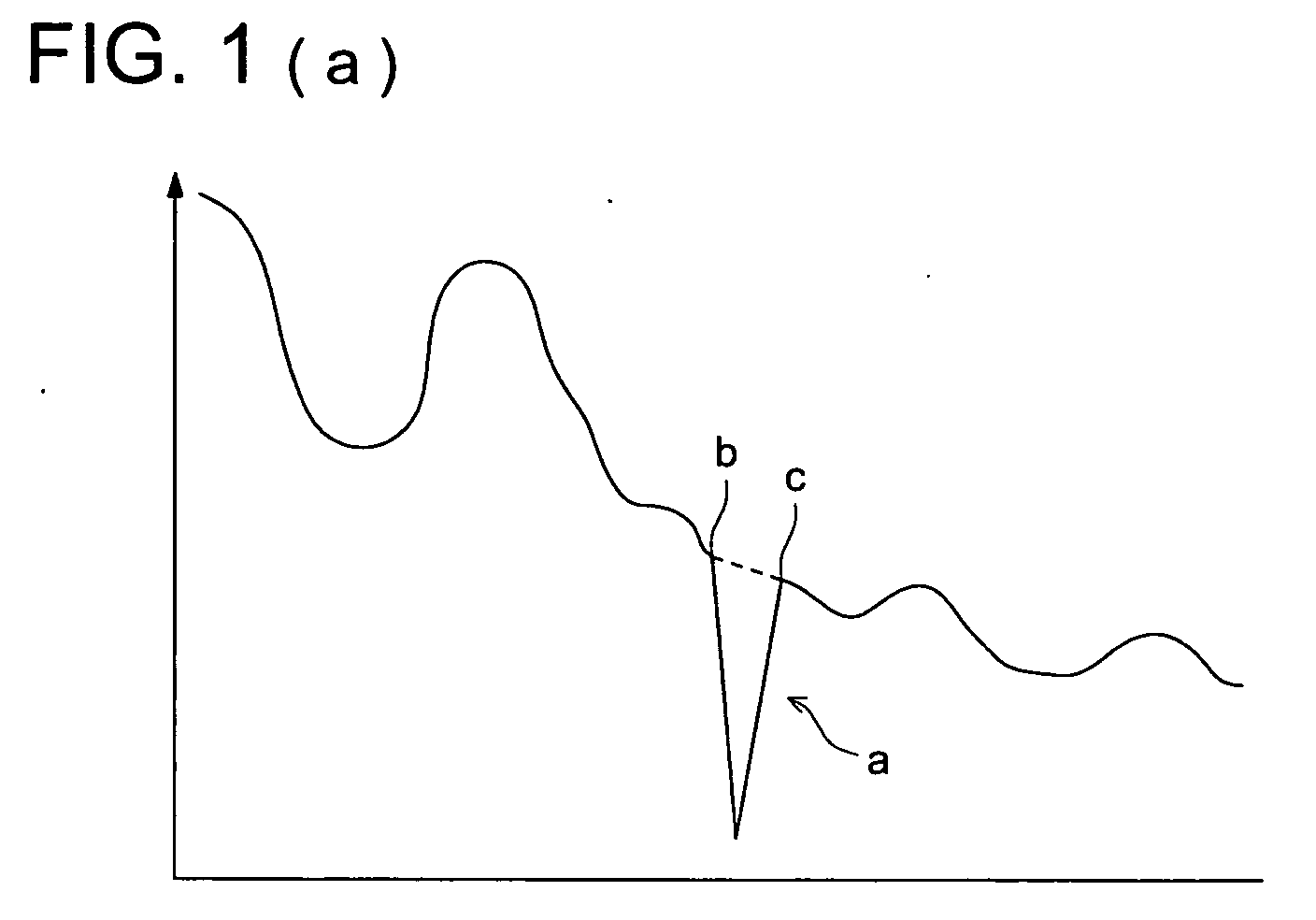
Fig. 1(a) and Fig. 1(b) show typical graphs of the
image signal having the defect pixel. Both curves depicted
in Fig. 1(a) and Fig. 1(b) indicate the same image signal,
and distances between positions of pixels, and a certain
position in the recording medium are plotted on the
horizontal axis, while signal intensities of the image
signals for every pixel are plotted on the vertical axis.
As shown in Fig. 1(a), according to the conventional
compensation processing, the signal intensity of defect pixel
"a" is compensated for, so that it coincides with an average
value of signal intensities of non-defect pixels "b", "c",
and the signal intensity of non-defect pixel "b" is jointed
to that of non-defect pixel "c" with a linear line between
them. Accordingly, sometimes, the viewer feels a sense of
incongruity for the compensated image. On the other hand, as
shown in Fig. 1(b), according to the present invention, since
the signal intensity of the defect pixel is compensated for,
so that the first order differential values of the image
signals of the defect pixel and those of the non-defect
pixels adjacent to the defect pixel continue to each other,
namely, the signal intensities of the defect pixel depict the
continuously curved line, it becomes possible to obtain the
compensated image as a natural image without generating
discontinuity, which yields slight unevenness in the image,
and without giving a sense of incongruity to the viewer.
In order to compensate for the defect pixel so that the
first order differential values of the image signals of the
defect pixel and those of the non-defect pixels adjacent to
the defect pixel continue to each other, the multi-resolution
conversion processing is applied to the image signals so as
to acquire multi-resolution signals, and the compensation
processing is applied to the acquired multi-resolution
signals, and then, the multi-resolution inverse-conversion
processing is applied to the compensated multi-resolution
signals so as to restructure the compensated image signals.
The multiple resolution conversion is a generic name of
the methods represented by the wavelet conversion, the full-restructuring
filter bank, the Laplacian pyramid, etc. In
this method, one converting operation allows the inputted
signals to be resolved into high-frequency component signals
and low-frequency component signals, and then, a same kind of
converting operation is further applied to the acquired low-frequency
component signals, in order to obtain the multiple
resolution signals including a plurality of signals locating
in frequency bands being different relative to each other.
The multiple resolution signals can be restructured to the
original signals by applying the multiple resolution inverse-conversion
to the multiple resolution signals. The detailed
explanations of such the methods are set forth in, for
instance, "Wavelet and Filter banks" by G. Strang & T.
Nguyen, Wellesley-Cambridge Press. The summary of the
wavelet transform will be described in the following.
The wavelet transform is operated as follows: In the
first place, the following wavelet function shown in equation
(1), where vibration is observed in a finite range as shown
in Fig. 2, is used to obtain the wavelet transform
coefficient <f, ψ
a, b> with respect to input signal f(x) by
employing equation (2). Through this process, input signal
is converted into the sum total of the wavelet function shown
in equation (3).
In the above equation, "a" denotes the scale of the
wavelet function, and "b" the position of the wavelet
function. As shown in Fig. 2, as the value "a" is greater,
the frequency of the wavelet function ψa, b(x) is smaller.
The position where the wavelet function ψa, b(x) vibrates
moves according to the value of position "b". Thus, equation
(3) signifies that the input signal f(x) is decomposed into
the sum total of the wavelet function ψa, b(x) having various
scales and positions.
A great number of the wavelet functions are known, that
allow the above-mentioned conversion. In the field of image
processing, there have been specifically well known the
orthogonal wavelet conversion and the bi-orthogonal wavelet
conversion, which make it possible to conduct calculations at
a high-speed rate. Further, the Dyadic Wavelet transform is
more desirable, compared to the orthogonal wavelet conversion
or the bi-orthogonal wavelet conversion, since it is possible
for the Dyadic Wavelet transform to recognize the image
defect more accurately based on the defect detecting signals
after the converting operation.
Next, the orthogonal wavelet conversion and the bi-orthogonal
wavelet conversion will be detailed in the
following. In the orthogonal wavelet conversion and the bi-orthogonal
wavelet conversion, the wavelet function defined
by equation (4) shown in the following is employed.
where "i" denotes a natural number.
Comparison between equation (4) and equation (1) shows
that the value of scale "a" is defined discretely by an i-th
power of "2", in the orthogonal wavelet conversion and the
bi-orthogonal wavelet conversion. This value "i" is called a
level.
In practical terms, level "i" is restricted up to
finite upper limit N, and input signal is converted as shown
in equation (5), equation (6) and equation (7).
The second term of equation (5) denotes that the low
frequency band component of the residue that cannot be
represented by the sum total of wavelet function ψ1, j(x) of
level 1 is represented in terms of the sum total of scaling
function 1, j(x). An adequate scaling function in response
to the wavelet function is employed (refer to the
aforementioned reference). This means that input signal
f(x) ≡ S0 is decomposed into the high frequency band component
W1 and low frequency band component Si of level 1 by the
wavelet transform of level 1 shown in equation (5).
Incidentally, in the image signals, the high frequency
band component represents fine structures, namely, sharply
changing structures, in the image, for instance, like hears
and lashes, while the low frequency band component represents
coarse structures, namely, moderately changing structures, in
the image, like cheeks.
Since the minimum traveling unit of the wavelet
function ψi, j(x) is 2i, each of the signal volume of high
frequency band component W1 and low frequency band component
S1 with respect to the signal volume of input signal "S0" is
1/2. The sum total of the signal volumes of high frequency
band component W1 and low frequency band component S1 is
equal to the signal volume of input signal "S0". The low
frequency band component S1, obtained by the wavelet
transform of level 1, is decomposed into high frequency band
component W2 and low frequency band component S2 of level 2
by equation (6). After that, transform is repeated up to
level N, whereby input signal "S0" is decomposed into the sum
total of the high frequency band components of levels 1
through N and the sum of the low frequency band components of
level N, as shown in equation (7).
It has been well known that the wavelet transform of
level 1, shown in equation (6), can be computed by the
filtering process, which employs low-pass filter LPF and
high-pass filter HPF as shown in Fig. 3 (refer to "Wavelet
and Filter banks" by G. Strang & T. Nguyen, Wellesley-Cambridge
Press).
As shown in Fig. 3, input signal "S0" can be decomposed
into the high frequency band component and the low frequency
band component, which are obtained by the orthogonal wavelet
conversion of level 1 or the bi-orthogonal wavelet conversion
of level 1, by processing input signal "S0" with low-pass
filter LPF and high-pass filter HPF and by thinning out input
signal "S0" at every other samples. Incidentally, in Fig. 3,
symbol 2↓ shows the down sampling where every other samples
are removed (thinned out).
The filter coefficients of low-pass filter LPF and
high-pass filter HPF to be employed for the processing are
appropriately determined corresponding to the wavelet
function (refer to the reference document mentioned above).
The wavelet transform of level 1 for the two-dimensional
signals, such as the defect detecting signals and
the image signals, is conducted in the filtering process as
shown in Fig. 4. Initially, the filter processing is applied
to input signal Sn-1 by means of low-pass filter LPFx and
high-pass filter HPFx in the direction of "x", and then, the
down sampling is conducted in the direction of "x". By
conducting such the processing, input signal Sn-1 is
decomposed into low frequency band component SXn and high
frequency band component WXn. Further, the filter processing
is applied to low frequency band component SXn and high
frequency band component WXn by means of low-pass filter LPFy
and high-pass filter HPFy in the direction of "y", and then,
the down sampling is conducted in the direction of "y".
According to the filtering process mentioned above,
input signal Sn-1 can be decomposed into three high frequency
band components Wvn, Whn, Wdn and one low frequency band
component Sn. Since each of the signal volumes of Wvn, Whn,
Wdn and Sn, generated by a single wavelet transform
operation, is 1/2 of that of the input signal Sn-1 prior to
decomposition in both vertical and horizontal directions, the
total sum of signal volumes of four components subsequent to
decomposition is equal to the signal Sn-1 prior to
decomposition.
Incidentally, the suffix "x", subscripted as LPFx, HPFx
and 2↓x as shown in Fig. 4, indicates the processing in the
direction of "x", while the suffix "y", subscripted as LPFy,
HPFy and 2↓y as shown in Fig. 3, indicates the processing in
the direction of "y".
Fig. 5 shows the type process of decomposing input
signal "S0" by means of the wavelet transform of level 1,
level 2 and level 3. As the level number "i" increases, the
image signal is further thinned out by the down sampling
operation, and the decomposed image is getting small.
Further, it has been well known that, by applying the
wavelet inverse transform, which would be calculated in the
filtering process, or the like, to Wvn, Whn, Wdn and Sn
generated by decomposition processing, the signal Sn-1 prior
to decomposition can be fully reconstructed as shown in Fig.
6. Incidentally, in Fig. 6, LPF' indicates a low-pass filter
for inverse transform, while HPF' indicates a high-pass
filter for inverse transform. Further, 2↑ denotes the up-sampling
where zero is inserted into every other signals.
Still further, the suffix "x", subscripted as LPF'x, HPF'x
and 2↑x, indicates the processing in the direction of "x",
while the suffix "y", subscripted as LPF'y, HPF'y and 2↑y,
indicates the processing in the direction of "y".
As shown in Fig. 6, low frequency band component SXn
can be obtained by adding a signal, which is acquired by up-sampling
Sn in the direction of "y" and processing with low-pass
filter LPF'y in the direction of "y", and another
signal, which is acquired by up-sampling Whn in the direction
of "y" and processing with high-pass filter HPF'y in the
direction of "y", to each other. As well as the above
process, WXn is generated from Wvn and Wdn.
Further, the signal Sn-1 prior to decomposition can be
reconstructed by adding a signal, which is acquired by up-sampling
SXn in the direction of "x" and processing with low-pass
filter LPF'x in the direction of "x", and another
signal, which is acquired by up-sampling WXn in the direction
of "x" and processing with high-pass filter HPF'x in the
direction of "x", to each other.
In case of the orthogonal wavelet conversion, the
coefficient of the filter employed for the inverse
transforming operation is the same as that of the filter
employed for the transforming operation. On the other hand,
in case of the bi-orthogonal wavelet conversion, the
coefficient of the filter employed for the inverse
transforming operation is different from that of the filter
employed for the transforming operation (refer to the
aforementioned reference document).
When the defect pixel is compensated for with respect
to each of the high frequency band component and the low
frequency band component by applying the multi-resolution
conversion processing according to the abovementioned method,
it is applicable that compensation processing methods, which
are either similar or different to each other, are
respectively applied to the defect pixels in both components.
An interpolation processing method based on the signal
intensities of non-defect signals adjacent to the defect
pixel can be cited as a concrete method for compensating for
the high frequency band component of the defect pixel. An
interpolation processing method similar to the above can be
employed as a concrete method for compensating for the low
frequency band component of the defect pixel.
Since it is possible to compensate for the defect pixel
so that first order differential values of the visible light
image signals of the defect pixel and those of the non-defect
pixels adjacent to the defect pixel continue to each other,
by restructuring the image signals through the process of the
multi-resolution inverse-conversion after compensating for a
part corresponding to the defect pixel of each frequency band
component, it becomes possible to obtain the compensated
image as a natural image without generating discontinuity,
which yields slight unevenness in the image.
As mentioned in the foregoing, it is desirable that the
Dyadic Wavelet transform is employed as the multi-resolution
conversion processing, when applying it to the image signals.
Incidentally, detailed explanations in regard to the Dyadic
Wavelet transform are set forth in "Singularity detection and
processing with wavelets" by S. Mallat and W. L. Hwang, IEEE
Trans. Inform. Theory 38 617 (1992), "Characterization of
signal from multiscale edges" by S. Mallet and S. Zhong, IEEE
Trans. Pattern Anal. Machine Intel. 14 710 (1992), and "A
wavelet tour of signal processing 2ed." by S. Mallat,
Academic Press.
The wavelet function employed in the Dyadic Wavelet
transform is defined by equation (8) shown below.
where "i" denotes a natural number.
The Wavelet functions of the orthogonal wavelet
transform and the bi-orthogonal wavelet transform are
discretely defined when the minimum traveling unit of the
position on level "i" is 2i, as described above. By
contrast, in the Dyadic Wavelet transform, the minimum
traveling unit of the position is kept constant, regardless
of level "i".
In other words, in the Dyadic Wavelet transform, since
"i" does not appear at the position of the wavelet function
indicated by "b" in equation (1), for instance, like 2i, the
minimum traveling unit of the position is always kept
constant, regardless of its level number. Accordingly,
unlike the orthogonal wavelet transform and the bi-orthogonal
wavelet transform, the down-sampling operation at the time of
calculation in the filtering process is not required for the
Dyadic Wavelet transform. Due to this difference, the Dyadic
Wavelet transform has the following characteristics.
Characteristic 1: The signal volume of each of high
frequency band component W
i and low frequency band component
S
i generated by the Dyadic Wavelet transform of
level 1 shown
by equation (9) is the same as that of signal S
i-1 prior to
transform.
Characteristic 2: The scaling function i, j(x) and the
wavelet function ψi, j(x) fulfill the following relationship
shown by equation (10).
[Eq. 10]
ψi,j(x) = ∂∂x i,j(x)
Thus, the high frequency band component Wi generated by
the Dyadic Wavelet transform of level 1 represents the first
differential (gradient) of the low frequency band component
Si.
Characteristic 3: With respect to Wi · γi (hereinafter
referred to as "compensated high frequency band component)
obtained by multiplying the coefficient γi (refer to the
aforementioned reference documents in regard to the Dyadic
Wavelet transform) determined in response to the level "i" of
the Wavelet transform, by high frequency band component, the
relationship between levels of the signal intensities of
compensated high frequency band components Wi · γi subsequent
to the above-mentioned transform obeys a certain rule, in
response to the singularity of the changes of input signals,
as described in the following.
Fig. 7 shows exemplified waveforms of: input signal
"S0" at line (a); compensated high frequency band component
W1 · γ1, acquired by the Dyadic Wavelet transform of level 1,
at line (b); compensated high frequency band component W2 · γ2,
acquired by the Dyadic Wavelet transform of level 2, at line
(c); compensated high frequency band component W3 · γ3,
acquired by the Dyadic Wavelet transform of level 3, at line
(d); and compensated high frequency band component W4 · γ4,
acquired by the Dyadic Wavelet transform of level 4, at line
(e).
Observing the changes of the signal intensities step by
step, the signal intensity of the compensated high frequency
band component Wi · γi, corresponding to a gradual change of
the signal intensity shown at "1" and "4" of line (a),
increases according as the level number "i" increases, as
shown in line (b) through line (e).
With respect to input signal "S0", the signal intensity
of the compensated high frequency band component Wi · γi.
corresponding to a stepwise signal change shown at "2" of
line (a), is kept constant irrespective of the level number
"i". Further, with respect to input signal "S0", the signal
intensity of the compensated high frequency band component Wi
· γi, corresponding to a signal change of δ-function shown at
"3" of line (a), decreases according as the level number "i"
increases, as shown in line (b) through line (e).
Characteristic 4: Unlike the above-mentioned method of
the orthogonal wavelet transform and the bi-orthogonal
wavelet transform, the method of Dyadic Wavelet transform of
level 1 in respect to the two-dimensional signals such as the
defect detecting signals is followed as shown in Fig. 8. As
shown in Fig. 8, in the Dyadic Wavelet transform of level 1,
low frequency band component Sn can be acquired by processing
input signal Sn-1 with low-pass filter LPFx in the direction
of "x" and low-pass filter LPFy in the direction of "y".
Further, a high frequency band component Wxn can be acquired
by processing input signal Sn-1 with high-pass filter HPFx in
the direction of "x", while another high frequency band
component Wyn can be acquired by processing input signal Sn-1
with high-pass filter HPFy in the direction of "y".
The low frequency band component Sn-1 is decomposed into
two high frequency band components Wxn, Wyn and one low
frequency band component Sn by the Dyadic Wavelet transform
of level 1. Two high frequency band components correspond to
components x and y of the change vector Vn in the two
dimensions of the low frequency band component Sn. The
magnitude Mn of the change vector Vn and angle of deflection
An are given by equation (11) and equation (12) shown as
follow.
[Eq. 11]
Mn = Wx2 n + Wy2 n
An = argument (Wxn + iWyn)
Sn-1 prior to transform can be reconfigured when the
Dyadic Wavelet inverse transform shown in Fig. 8 is applied
to two high frequency band components Wxn, Wyn and one low
frequency band component Sn. In other words, input signal Sn-1
prior to transform can be reconstructed by adding the
signals of: the signal acquired by processing low frequency
band component Sn with low-pass filters LPFx and LPFy, both
used for the forward transform in the directions of "x" and
"y"; the signal acquired by processing high frequency band
component Wxn with high-pass filter HPF'x for inverse
transform in the direction of "x" and low-pass filter LPF'y
for inverse transform in the direction of "y"; and the signal
acquired by processing high frequency band component Wyn with
low-pass filter LPF'x for inverse transform in the direction
of "x" and high-pass filter HPF'y for inverse transform in
the direction of "y"; together.
Next, referring to Fig. 10, the method for acquiring
compensated image signals S0', which are compensated for in
such a manner that the first order differential values of the
image signals of the defect pixel and those of the non-defect
pixels adjacent to the defect pixel continue to each other,
will be detailed in the following. The method includes the
steps of applying the Dyadic Wavelet transform of level N to
the defect detecting signal S0 (input signal), conducting
compensation processing with respect to the defect pixel of
each of the acquired signals and applying the multi-resolution
inverse-conversion to the processed signals so as
to generate compensated image signals S0'.
In the Dyadic Wavelet transform of level 1 for input
signal "S0", input signal "S0" is decomposed into two high
frequency band components Wx1, Wy1 and low frequency band
component S1 by the same filtering process as that shown in
Fig. 8. In the Dyadic Wavelet transform of level 2, low
frequency band component S1 is further decomposed into two
high frequency band components Wx2, Wy2 and low frequency
band component S2 by the same filtering process. By
repeating the abovementioned operational processing up to
level N, input signal "S0" is decomposed into a plurality of
high frequency band components Wx1, Wx2, --- Wxn, Wy1, Wy2, --
- Wyn and a single low frequency band component Sn.
Further, compensation processing is applied to each of
the high frequency band components and the low frequency band
component corresponding to the defect pixel, and then the
multi-resolution inverse-conversion is performed.
The multi-resolution inverse-conversion is performed
according to the procedure shown in Fig. 9. Concretely
speaking, the compensated low frequency band component Sn-1'
of level (N-1) is restructured from the two compensated high
frequency band components Wxn', Wyn' of level N and the
compensated low frequency band component Sn' of level N. By
repeating this operation shown in Fig. 9, the compensated low
frequency band component S1' of level 1 is restructured from
the two compensated high frequency band components Wx2', Wy2'
of level 2 and the compensated low frequency band component
S2' of level 2. Successively, the compensated low frequency
band component S0' is restructured from the two compensated
high frequency band components Wx1', Wy1' of level 1 and the
compensated low frequency band component S1' of level 1.
The filter coefficients of the filters employed for the
processing are appropriately determined corresponding to the
wavelet functions. Further, in the Dyadic Wavelet transform,
the filter coefficients, employed for every level number, are
different relative to each other. The filtering coefficients
employed for level "n" are created by inserting 2n-1-1 zeros
into each interval between filtering coefficients for level
1. The abovementioned procedure is set forth in the
aforementioned reference document.
Incidentally, to compensate for the defect pixel with
respect to the low frequency band component and the high
frequency band components of each level acquired by the
Dyadic Wavelet transform, the interpolation processing, based
on the signal intensities of non-defect pixels adjacent to
the defect pixel, can be employed for such the compensation
processing, as well as in the case of the orthogonal wavelet
transform or the bi-orthogonal wavelet transform. Further,
it is also applicable that, with respect to the high
frequency band components, the compensation processing is
conducted so as to interpolate the phases of the high
frequency band components.
As described in the foregoing, unlike the orthogonal
wavelet transform or the bi-orthogonal wavelet transform, the
Dyadic Wavelet transform does not require the down-sampling
operation when converting the image signals. Accordingly, it
becomes possible to conduct the compensation processing of
the defect pixel in more detail than ever, without thinning
out the defect pixel itself and/or the non-defect pixels
adjacent to the defect pixel. As a result, discontinuities
in the compensated image, which might be perceived as a
slight unevenness in the image by the viewer, could not be
generated. Therefore, even for an image having fine
structures such as a close-up image of human face, it becomes
possible to compensate for the image so as to obtain a
natural image without spoiling the expression of the face or
the feel of its material.
Incidentally, to accurately recognize the defect pixel
when compensating for the defect pixel in the image signals,
it is desirable that the multi-resolution conversion
processing is applied to the defect detecting signals, in
order to determine the presence or absence of the defect
pixel based on the converted signals.
As conventionally performed, it is possible to
recognize the defect pixel by comparing the defect detecting
signals, acquired by scanning the image recorded on the
recording medium with the infrared light, with a threshold
value established in advance. The defect detecting signals
acquired by the abovementioned method, however, includes
noises generated at the time of photoelectronic conversion by
the CCD sensor, or at the time of amplifying the signals.
Accordingly, there has been a fear that each of pixels to be
determined originally as defect pixels is not necessary
recognized as the defect pixel, depending on the established
threshold value.
On the contrary to the above, since the high frequency
band components, acquired by applying the multi-resolution
conversion processing to the defect detecting signals,
include little noise in the form of signal intensity, it is
possible to accurately recognize the defect pixel. Further,
by recognizing the defect pixel in a multi-resolution space
and by compensating for the image signal corresponding to the
recognized defect pixel in the same multi-resolution space,
it becomes possible to make the compensated image having more
natural impression than ever.
As the next step, an image-recording apparatus provided
with an image-processing section (image-processing
apparatus), which compensates for the defect pixel of the
image signals in a manner as described in the foregoing, will
be detailed in the following. Fig. 11 shows an exemplified
outlook configuration of image-recording apparatus 1 embodied
in the present invention.
As shown in Fig. 11, image-recording apparatus 1 is
provided with magazine loading section 3 mounted on a side of
housing body 2, exposure processing section 4 mounted inside
housing body 2 and print creating section 5. Further, tray 6
for receiving ejected prints is installed on another side of
housing body 2. Still further, CRT 7 (Cathode Ray Tube 7)
serving as a display device, film scanning section 8,
reflected document input section 9 and operating section 10
are provided on the upper side of housing body 2. Operating
section 10 includes inputting means 11 constituted by a touch
panel, etc. Still further, image reading section 13 being
capable of reading image information stored in various kinds
of digital recording mediums including the floppy (Registered
Trade Mark) disk, etc. and image writing section 14 being
capable of writing (outputting) image signals into various
kinds of digital recording mediums including the floppy
(Registered Trade Mark) disk, etc. are installed in housing
body 2. Still further, as shown in Fig. 12, control section
15 for intensively controlling the abovementioned sections is
also installed in housing body 2.
The photosensitive material serving as an image
outputting medium is loaded in magazine loading section 3.
The photosensitive material is made of, for instance, a
silver-halide photosensitive paper including silver-halide
photosensitive heat-developing materials. The photosensitive
materials having various sizes, such as service size, high-vision
size, panorama size, A4-size, visiting card size, etc.
can be loaded into magazine loading section 3. Under the
command signals sent from control section 15, a conveying
means (not shown in the drawings) takes out the
photosensitive material having a predetermined size from
magazine loading section 3 to convey it to exposure
processing section 4.
Exposure processing section 4 exposes the
photosensitive material based on the image signals to form a
latent image on the photosensitive material. After the
exposure processing is completed, the photosensitive material
is conveyed to print creating section 5. Corresponding to
the size of the photosensitive material, the prints having
various kinds of sizes, such as service size prints, high-vision
size prints, prints P1 of panorama size, etc., prints
P2 of A4-size, prints P3 of visiting card size, etc. are
created as shown in Fig. 12.
Print creating section 5 conducts developing and drying
operations for the conveyed photosensitive material to create
prints. Then, the created prints are ejected onto tray 6.
Incidentally, although image-recording apparatus 1, in
which the conveyed photosensitive material is developed and
dried to create the prints, is exemplified in Fig. 11, the
scope of the present invention is not limited to the above.
An apparatus employing any kind of methods, including, for
instance, an ink-jetting method, an electro-photographic
method, a heat-sensitive method and a sublimation method, is
also applicable in the present invention, as far as the
apparatus forms an image based on image signals.
CRT 7 displays the processed image, the contents of the
operation, etc. according to the command signals sent from
control section 15. Incidentally, the scope of the display
device is not limited to the CRT, but a liquid-crystal
display, a plasma display panel, etc. are also applicable in
the present invention.
As shown in Fig. 12, film scanning section 8 reads the
image and the defect of transparent recording medium N, such
as a negative film, a reversal film, etc., on which an image
captured by an analogue camera, etc. is developed, and for
this purpose, provided with a film scanner.
The image-reading light source, the defect detecting
light source, the scanning means for scanning the image-reading
light and the defect detecting light emitted from
such the light sources, the light converging means for
converging the image-reading light and the defect detecting
light penetrated through transparent recording medium N,
photoelectronic converting element such as the CCD sensor,
etc. constitute the film scanner.
In the film scanner, the image-reading light and the
defect detecting light are scanned on transparent recording
medium N, and the lights penetrated through transparent
recording medium N are converged and focused onto the
photoelectronic converting element by means of the light
converging means, in order to acquire the image signals and
the defect detecting signal as electronic signals
photoelectronically converted by the photoelectronic
converting element. The acquired image signals and the
defect detecting signal are transferred to control section
15.
Reflected document input section 9 reads the image and
the defect of non-transparent recording medium P, such as a
silver-halide printing paper, a color paper, etc., on which
an image captured by an analogue camera, etc. is developed
(outputted), and for this purpose, provided with a flat bed
scanner.
The image-reading light source, the defect detecting
light source, the scanning means, the light converging means,
the CCD sensor, etc. constitute the flat bed scanner, as well
as film scanning section 8.
In reflected document input section 9, the image-reading
light and the defect detecting light are scanned on
non-transparent recording medium P, and the lights reflected
from the recording medium are converged and focused onto the
CCD sensor by means of the light converging means, in order
to acquire the image signals and the defect detecting signal
photoelectronically converted by the CCD sensor. The
acquired image signals and the defect detecting signal are
transferred to control section 15.
In film scanning section 8 and reflected document input
section 9, three visible lights of R, G, B are employed as
the image-reading lights to acquire respective image signals
of R, G, B.
Further, in film scanning section 8 and reflected
document input section 9, an infrared light is employed as
the defect detecting light. It is applicable that a certain
threshold value for recognizing the defect pixel is
established in advance, to determine the presence or absence
of the defect pixel by comparing the signal intensity of the
defect detecting signal with the established threshold value.
Or, it is also applicable that the multi-resolution
conversion processing is applied to the defect detecting
signals in the manner described in the above, to determine
the presence or absence of the defect pixel based on the
acquired high frequency band components.
Image reading section 13 inputs frame image
information, in regard to images captured by the digital
camera, etc., into image-recording apparatus 1 through
various kinds of digital storage mediums 16a, 16b.
Image reading section 13 is provided with PC card
adaptor 13a, floppy (Registered Trade Mark) disc adaptor 13b
to read the frame image information stored in them and to
transfer the acquired image information to control section
15. Incidentally, for instance, the PC card reader or the PC
card slot is employed as PC card adaptor 13a.
As well as the image signals inputted from film
scanning section 8 or reflected document input section 9,
an image-processing is applied to the image signals, read and
inputted from image reading section 13, as needed, so that
the processed image signals can be outputted onto the
photosensitive material, etc.
Further, in image-recording apparatus 1, an image-processing,
etc. are applied to the frame image information
inputted from film scanning section 8, reflected document
input section 9 and image reading section 13, and then, the
processed image can be outputted onto not only the
photosensitive material or CRT 7, but also various kinds of
outputting mediums 17a, 17b, 17c.
Image writing section 14 is provided with a floppy
(Registered Trade Mark) disk adaptor 14a, a MO adaptor 14b
and an optical disk adaptor 14c. Accordingly, a floppy
(Registered Trade Mark) disk 17a, a MO (Magneto-Optics type
storage device) disk 17b and an optical disk 17c, etc. can be
employed as outputting mediums.
Further, as shown in Fig. 13, control section 15 is
provided with communication means 18, which makes it possible
to work as a network printer, so to speak, having a function
for directly receiving the image signals, representing the
captured image, and printing commands from another computer
through a communication network, such as LAN, WAN, Internet,
etc. It is also possible to transmit the image signals,
representing the captured image to which the image processing
of the present invention is already applied, and the
associated order information to a computer located at a
remote site through another computer in the facility
concerned and the Internet, etc.
Next, control section 15 will be detailed in the
following. Control section 15 is provided with image-processing
section 20, in which the presence or absence of
the defect pixel is recognized by a CPU (not shown in the
drawings) cooperated with various controlling programs
including a defect determining program, an image-processing
program, etc., stored in the storage device, such as ROM (not
shown in the drawings), etc. When the CPU recognizes the
presence of the defect pixel, the multi-resolution conversion
processing is applied to the image signals, and then, the
compensation processing is respectively applied to the high
frequency band components and the low frequency band
component to generate the compensated image signals, based on
which the reproduced image is outputted onto the outputting
medium.
As shown in Fig. 13, image-processing section 20 is
provided with film scan data processing section 21, reflected
document scan data processing section 22, image data format
decoding processing section 23, image adjustment processing
section 24, CRT-specific processing section 25, first
printer-specific processing sections 26, second printer-specific
processing sections 27, image-data format creating
section 28 and recognizing section 29 for recognizing the
presence or absence of the defect pixel based on the defect
detecting signals.
In film scan data processing section 21, various kinds
of processing, such as calibrating operations inherent to
film scanning section 8, a negative-to-positive inversion in
case of negative document, a gray balance adjustment, a
contrast adjustment, etc., are applied to the image signals
inputted from film scanning section 8, and then, processed
image signals are transmitted to image adjustment processing
section 24. A film size and a type of negative/positive, as
well as an ISO sensitivity, a manufacturer's name,
information on the main subject and information on
photographic conditions (for example, information described
in APS), optically or magnetically recorded on the film, are
also transmitted sent to the image adjustment processing
section 24.
In reflected document scan data processing section 22,
the calibrating operations inherent to reflected document
input section 9, the negative-to-positive inversion in case
of negative document, the gray balance adjustment, the
contrast adjustment, etc., are applied to the image signals
inputted from reflected document input section 9 and then,
processed image signals are transmitted to image adjustment
processing section 24.
Image data format decoding processing section 23
decodes the image data format of the image signals inputted
from image reading section 13 or communication means 18, so
as to convert the image signals to a data format suitable for
the calculating operations in image adjustment processing
section 24 by performing a converting operation of the method
for reproducing the compressed code or representing color
signals, etc., according to the decoded data format, as
needed, and then, transmits converted image signals to image
adjustment processing section 24.
Under the command signals sent from operating section
10 or control section 15, when the image signals received
from film scanning section 8 or reflected document input
section 9 include the defect pixel, judging from the
recognized result made by recognizing section 29, image
adjustment processing section 24 conducts the compensation
processing for the defect pixel to transmit the processed
image signals to CRT-specific processing section 25, first
printer-specific processing sections 26, second printer-specific
processing sections 27 and image-data format
creating section 28.
Incidentally, when the image signals sent from image
reading section 13 or communication means 18 include the
defect detecting signal, image adjustment processing section
24 conducts the processing for compensating for the signal
intensity of the defect pixel concerned, based on the
recognized result made by recognizing section 29, as well.
CRT-specific processing section 25 applies a pixel
number changing processing, a color matching processing, etc.
to the compensated image signals received from image
adjustment processing section 24, as needed, and then,
transmits display signals synthesized with information
necessary for displaying, such as control information, etc.,
to CRT 7.
First printer-specific processing sections 26 applies a
calibrating processing inherent to exposure processing
section 4, a color matching processing, a pixel number
changing processing, etc. to the compensated image signals
received from image adjustment processing section 24, as
needed, and then, transmits processed image signals to
exposure processing section 4.
In case that external printing apparatus 30, such as a
large-sized printing apparatus, etc., is coupled to image-recording
apparatus 1 embodied in the present invention, a
printer-specific processing section, such as second printer-specific
processing sections 27 shown in Fig. 13, is provided
for every apparatus, so as to conduct an appropriate
calibrating processing for each specific printer, a color
matching processing, a pixel number change processing, etc.
In image-data format creating section 28, the format of
the image signals received from image adjustment processing
section 24 are converted to one of various kinds of general-purpose
image formats, represented by JPEG (Joint
Photographic Coding Experts Group), TIFF (Tagged Image File
Format), Exif (Exchangeable Image File Format), etc., as
needed, and then, the converted image signals are transmitted
to image writing section 14 or communication means 18.
Recognizing section 29 recognizes the presence or
absence of the defect pixel based on the defect detecting
signals received from film scanning section 8 or reflected
document input section 9. It is applicable that the presence
or absence of the defect pixel is recognized by comparing the
defect detecting signal with the threshold value.
Alternatively, it is also applicable that the multi-resolution
conversion processing is applied to the defect
detecting signals in image adjustment processing section 24
to recognize the presence or absence of the defect pixel
based on the acquired high frequency band components.
The aforementioned sections, such as film scan data
processing section 21, reflected document scan data
processing section 22, image data format decoding processing
section 23, image adjustment processing section 24, CRT-specific
processing section 25, first printer-specific
processing sections 26, second printer-specific processing
sections 27 and image-data format creating section 28, are
eventually established for helping the understandings of the
functions of image-processing section 20 embodied in the
present invention. Accordingly, it is needless to say that
each of these sections is not necessary established as a
physically independent device, but is possibly established as
a kind of software processing section with respect to a
single CPU (Central Processing Unit).
As a next step, with respect to the compensation
processing for the defect pixel of the image signals, which
is conducted in image adjustment processing section 24 shown
in Fig. 13, embodiment 1 - embodiment 3 will be detailed in
the following.
[EMBODIMENT 1]
In the embodiment 1, the bi-orthogonal wavelet
transform is applied for compensating for the defect pixel of
the image signals. Fig. 14 shows a block diagram of the
system of embodiment 1 in regard to the bi-orthogonal wavelet
transform of the image signals, performed in image adjustment
processing section 24.
The bi-orthogonal wavelet transform of level 1 is
conducted with respect to every image signal of R, G, B.
Incidentally, in Fig. 14, each of image signals is
comprehensively represented by So.
Initially, image signals S0 is processed by low-pass
filter LPFx of the direction of "x" and high-pass filter HPFx
of the direction of "y" to decompose them into low frequency
band component SX1 and high frequency band component WX1 by
applying the down-sampling operation in the direction of "x".
Successively, the filter processing and the down-sampling
processing in the direction of "y" are applied to
both low frequency band component SX1 and high frequency band
component WX1 by means of low-pass filter LPFy and high-pass
filter HPFy, so as to acquire low frequency band component S1
and three high frequency band components Wh1, Wv1, Wd1.
Incidentally, the filters having the following
coefficients (Cohen, Daubechies, Feauveau 5-3) shown in Table
1 are employed in the bi-orthogonal wavelet transform of
level 1 and its inverse-transform.
| | Forward-transform | Inverse-transform |
| x | HPF | LPF | HPF' | LPF' |
| - 2 | | -0.176777 | 0.176777 |
| - 1 | 0.353553 | 0.353553 | 0.353553 | 0.353553 |
| 0 | -0.707107 | 1.06066 | -1.06066 | 0.707107 |
| 1 | 0.353553 | 0.353553 | 0.353553 | 0.353553 |
| 2 | | -0.176777 | 0.176777 |
Incidentally, in Table 1, the coefficients for x = 0
corresponds to a current pixel currently being processed, the
coefficients for x = -1 corresponds to a pixel just before
the current pixel, the coefficients for x = 1 corresponds to
a pixel just after the current pixel (following as well).
Next, with respect to the defect pixel recognized by
recognizing section 29, the interpolation processing is
applied to each of low frequency band component S1 and high
frequency band components Wh1, Wv1, Wd1, based on the signal
intensities of non-defect pixels adjacent to the defect
pixel, to acquire low frequency band component S1' and high
frequency band components Wh1', Wv1', Wd1', in each of which
the signal intensity of the defect pixel is compensating for.
Then, the image signal S0' is restructured from
compensated low frequency band component S1' and compensated
high frequency band components Wh1', Wv1', Wd1' by means of
the inverse-transform operation. Fig. 14 shows a
restructuring process of the image signals S0'. As shown in
Fig. 14, initially, signal SX1' is obtained by adding the
signals, acquired by respectively applying the up-sampling
processing and the predetermined filter processing to low
frequency band component S1' and high frequency band
component Wh1', to each other. Further, signal WX1' is
obtained by adding the signals, acquired by respectively
applying the up-sampling processing and the predetermined
filter processing to tow high frequency band components Wv1',
Wd1', to each other, as well. Finally, the image signal S0'
is restructured by respectively applying the up-sampling
processing and the predetermined filter processing to signal
SX1' and signal WX1', to each other.
According to the embodiment 1 of the present invention,
by applying the bi-orthogonal wavelet transform to the image
signals and by applying the interpolation processing to the
high frequency band components and the low frequency band
component, it becomes possible to obtain an output image
having an impression naturally compensated for without
generating discontinuity giving a sense of slight unevenness
to the image.
[EMBODIMENT 2]
Next, embodiment 2 will be detailed in the following.
In the embodiment 2, the Dyadic Wavelet transform is applied
to the image signals to compensate for the defect pixel of
the image signals. Fig. 15 shows a block diagram of the
system of embodiment 1 in regard to the Dyadic Wavelet
transform of the image signals, performed in image adjustment
processing section 24.
As shown in Fig. 15, when performing the Dyadic Wavelet
transform of
level 1, initially, the image signal "S
0" is
decomposed into two high frequency band components WX
1, WY
1
and single low frequency band component S
1 by means of high-pass
filters HPF1
x, HPF1
y and low-pass filters LPF1
x, LPF1
y
having filter coefficients of
level 1 in the direction of "x"
and the direction of "y". Incidentally, the filter
coefficients employed for each of the filters are shown in
Table 2.
| x | HPF1 | LPF1 | HPF'1 | LPF'1 |
| - 3 | | | 0.0078125 | 0.0078125 |
| - 2 | | | 0.054685 | 0.046875 |
| - 1 | | 0.125 | 0.171875 | 0.1171875 |
| 0 | -2.0 | 0.375 | -0.171875 | 0.65625 |
| 1 | 2.0 | 0.375 | -0.054685 | 0.1171875 |
| 2 | | 0.125 | -0.0078125 | 0.046875 |
| 3 | | | | 0.0078125 |
Incidentally, in Table 2, the coefficients for x = 0
corresponds to a current pixel currently being processed, the
coefficients for x = -1 corresponds to a pixel just before
the current pixel, the coefficients for x = 1 corresponds to
a pixel just after the current pixel.
Further, although the Dyadic Wavelet transform of level
1 is conducted in the present embodiment, the filters having
coefficients, which are different relative to each other for
every level, are employed in the general-purpose Dyadic
Wavelet transform. A coefficient obtained by inserting 2n-1 -
1 zeros between coefficients of filters on level 1 is used as
a filter coefficient on level "n" (refer to the
aforementioned document).
Each of the compensation coefficients γ
i determined in
response to the level "i" of the Dyadic Wavelet transform is
shown in Table 3.
| i | γ |
| 1 | 0.66666667 |
| 2 | 0.89285714 |
| 3 | 0.97087379 |
| 4 | 0.99009901 |
| 5 | 1 |
The image signals are compensated for by means of the
interpolation processing, based on signal intensities of non-defect
pixels adjacent to the defect pixel, for the defect
pixels included in frequency band components Wx1, Wy1 and low
frequency band component S1, both acquired by the
abovementioned filter processing.
Then, the image signal S0' is restructured from
compensated low frequency band component S1' and compensated
high frequency band components Wx1', Wy1' by means of the
inverse-transform operation. Fig. 15 shows a restructuring
process of the image signals S0'. As shown in Fig. 15, the
image signal S0' is restructured by adding the signals, one
of which is acquired by applying the filter processing by
means of low-pass filters LPF1x, LPF1y, being the same as
those employed in the Dyadic Wavelet transform of level 1, to
low frequency band component S1', and another one of which is
acquired by applying the filter processing by means of high-pass
filters HPF'1x, HPF'1y, and low-pass filters LPF'1x,
LPF'1y, for inverse-transform, to high frequency band
components Wx1, Wy1, to each other.
According to the embodiment 2 of the present invention,
by applying the Dyadic Wavelet transform to the image signals
and by applying the interpolation processing to the high
frequency band components and the low frequency band
component, it becomes possible to obtain an output image
having an impression naturally compensated for without
generating discontinuity giving a sense of slight unevenness
to the image.
Further, unlike the orthogonal wavelet transform or the
bi-orthogonal wavelet transform, the Dyadic Wavelet transform
does not require the down-sampling operation when converting
the image signals. Accordingly, it becomes possible to
conduct the compensation processing of the defect pixel in
more detail than ever, without thinning out the defect pixel
itself and/or the non-defect pixels adjacent to the defect
pixel. Therefore, even for an image having fine structures
such as a close-up image of human face, it becomes possible
to compensate for the image so as to obtain a natural image
without spoiling the expression of the face or the feel of
its material.
Incidentally, although the Dyadic Wavelet transform of
level 1 is applied to the image signals in the embodiment 2,
it is needless say that the present invention is not limited
to the above, but the Dyadic Wavelet transform of higher
level would be possibly applied.
[EMBODIMENT 3]
Next, embodiment 3 will be detailed in the following.
In the embodiment 3, when recognizing section 29 conducts the
recognizing the defect pixel based on the defect detecting
signal, initially, the multi-resolution conversion processing
is applied to the defect detecting signal in image adjustment
processing section 24. Recognizing section 29 recognizes the
presence or absence of the defect pixel, based on the high
frequency band components acquired by the multi-resolution
conversion processing.
Fig. 16 shows a system block diagram in regard to the
multi-resolution conversion processing of defect detecting
signal SE0, performed in image adjustment processing section
24, in embodiment 3. In this embodiment, the Dyadic Wavelet
transform is employed for the multi-resolution conversion.
The defect detecting signal SE0 is decomposed into two high
frequency band components WEX1, WEY1 and a single low
frequency band component SE1 by conducting the filter
processing by means of high-pass filters HPF1x, HPF1y in the
directions of "x" and "y" and low-pass filters LPF1x, LPF1y
in the directions of "x" and "y", both having filter
coefficients of level 1. Incidentally, the filter
coefficients employed for each of the filters are shown in
Table 2.
Then, recognizing section 29 compares the signal
intensities of high frequency band components WEX1, WEY1 with
each other, to determine whether or not a certain specific
pixel is the defect pixel. When determining that the
specific pixel is the defect pixel, image adjustment
processing section 24 applies the Dyadic Wavelet transform of
level 1 to the image signals in the same manner as that
performed in embodiment 2, and applies the interpolation
processing, based on the signal intensities of non-defect
pixels adjacent to the defect pixel, to high frequency band
components Wx1, Wy1 and low frequency band component S1, so as
to compensating for the image signals.
Since high frequency band components Wx1, Wy1 of defect
detecting signal SE0, acquired by applying the Dyadic Wavelet
transform, include little noise component, it becomes
possible to accurately recognize the defect pixel. Further,
by recognizing the defect pixel in a multi-resolution space
and by compensating for the image signal corresponding to the
recognized defect pixel in the same multi-resolution space,
it becomes possible to make the compensated image having more
natural impression than ever.
Incidentally, although the defect recognition is
conducted by employing the high frequency band components
acquired by applying the Dyadic Wavelet transform of level 1,
serving as the multi-resolution conversion processing for
defect detecting signal SE0, in the embodiment 3, it would be
more desirable for improving the defect detecting accuracy
that the combination of the high frequency band components of
level 1 and other high frequency band components acquired by
applying the Dyadic Wavelet transform of level 2 and/or
higher level is employed for the defect recognition.
Further, without limiting to the Dyadic Wavelet transform,
other multi-resolution conversion processing, including the
orthogonal wavelet transform, the bi-orthogonal wavelet
transform, etc., can be also employed, as needed.
As described in the foregoing, according to the present
invention, the following effects can be attained.
Disclosed embodiment can be varied by a skilled person
without departing from the spirit and scope of the invention.