EP1429239A2 - Gleitkommamultiplizierung - Google Patents
Gleitkommamultiplizierung Download PDFInfo
- Publication number
- EP1429239A2 EP1429239A2 EP03027629A EP03027629A EP1429239A2 EP 1429239 A2 EP1429239 A2 EP 1429239A2 EP 03027629 A EP03027629 A EP 03027629A EP 03027629 A EP03027629 A EP 03027629A EP 1429239 A2 EP1429239 A2 EP 1429239A2
- Authority
- EP
- European Patent Office
- Prior art keywords
- mantissa
- bit
- multiplication
- partial
- addenda
- Prior art date
- Legal status (The legal status is an assumption and is not a legal conclusion. Google has not performed a legal analysis and makes no representation as to the accuracy of the status listed.)
- Withdrawn
Links
Images


Classifications
-
- G—PHYSICS
- G06—COMPUTING OR CALCULATING; COUNTING
- G06F—ELECTRIC DIGITAL DATA PROCESSING
- G06F7/00—Methods or arrangements for processing data by operating upon the order or content of the data handled
- G06F7/38—Methods or arrangements for performing computations using exclusively denominational number representation, e.g. using binary, ternary, decimal representation
- G06F7/48—Methods or arrangements for performing computations using exclusively denominational number representation, e.g. using binary, ternary, decimal representation using non-contact-making devices, e.g. tube, solid state device; using unspecified devices
- G06F7/483—Computations with numbers represented by a non-linear combination of denominational numbers, e.g. rational numbers, logarithmic number system or floating-point numbers
- G06F7/487—Multiplying; Dividing
- G06F7/4876—Multiplying
-
- G—PHYSICS
- G06—COMPUTING OR CALCULATING; COUNTING
- G06F—ELECTRIC DIGITAL DATA PROCESSING
- G06F7/00—Methods or arrangements for processing data by operating upon the order or content of the data handled
- G06F7/38—Methods or arrangements for performing computations using exclusively denominational number representation, e.g. using binary, ternary, decimal representation
- G06F7/48—Methods or arrangements for performing computations using exclusively denominational number representation, e.g. using binary, ternary, decimal representation using non-contact-making devices, e.g. tube, solid state device; using unspecified devices
- G06F7/483—Computations with numbers represented by a non-linear combination of denominational numbers, e.g. rational numbers, logarithmic number system or floating-point numbers
-
- G—PHYSICS
- G06—COMPUTING OR CALCULATING; COUNTING
- G06F—ELECTRIC DIGITAL DATA PROCESSING
- G06F7/00—Methods or arrangements for processing data by operating upon the order or content of the data handled
- G06F7/38—Methods or arrangements for performing computations using exclusively denominational number representation, e.g. using binary, ternary, decimal representation
- G06F7/48—Methods or arrangements for performing computations using exclusively denominational number representation, e.g. using binary, ternary, decimal representation using non-contact-making devices, e.g. tube, solid state device; using unspecified devices
- G06F7/499—Denomination or exception handling, e.g. rounding or overflow
- G06F7/49936—Normalisation mentioned as feature only
-
- G—PHYSICS
- G06—COMPUTING OR CALCULATING; COUNTING
- G06F—ELECTRIC DIGITAL DATA PROCESSING
- G06F7/00—Methods or arrangements for processing data by operating upon the order or content of the data handled
- G06F7/38—Methods or arrangements for performing computations using exclusively denominational number representation, e.g. using binary, ternary, decimal representation
- G06F7/48—Methods or arrangements for performing computations using exclusively denominational number representation, e.g. using binary, ternary, decimal representation using non-contact-making devices, e.g. tube, solid state device; using unspecified devices
- G06F7/499—Denomination or exception handling, e.g. rounding or overflow
- G06F7/49942—Significance control
- G06F7/49947—Rounding
Definitions
- the present invention relates to techniques for automatic execution of operations of multiplication, i.e., to techniques for generating, starting from at least one first binary digital signal and one second binary digital signal representing respective factors to be multiplied together, an output signal representing the product of these factors.
- the invention has been developed with particular attention paid to its possible application to the' multiplication of floating-point real numbers, with a view to its use in devices such as, for example, low-power-consumption electronic devices, in particular portable wireless devices.
- ALUs arithmetic logic units of electronic devices traditionally comprise multiplication units for floating-point numbers. These are typically circuits which, starting from a first binary digital signal and a second binary digital signal representing respective factors to be multiplied, expressed in floating-point format, generate an output signal, which is also expressed in floating-point format and represents the product of the factors multiplied together.
- a number represented in the floating-point form comprises three basic components: sign SGN, exponent E, and mantissa M.
- a representation in single precision of the real number f using: a number NS, equal to one, of sign bits SGN; a number NE, equal to 8, of exponent bits E; and a number NM equal to 23, of mantissa bits M.
- NS has the value 1
- NE has the value 11
- NM has the value 52.
- the sign bit SGN is always just one and assumes the value "0" to indicate a positive number, and the value "1" to indicate a negative number.
- the exponent E there is adopted a representation that envisages adding a fixed value, referred to as "bias", to a base exponent exp. For example, if the base exponent has the value 73 and the bias value is 127, the encoded exponent E has the value 200.
- the bias value is fixed and assumes the value 127 in single precision and the value 1023 in double precision.
- the adoption of the fixed bias value means that the lowest number will be represented in the exponent by a series of zeroes in binary form, whilst the highest one will be represented by a series of ones.
- the IEEE754 standard moreover adopts a representation, termed "denormalized representation", when the real number f has exponent zero and mantissa other than zero. This notation is used for representing the real numbers very close to zero.
- f (-1) SGN *0.M*2 (-bias-1) In this case, that is, there is not, hence, a one set before the mantissa M.
- IEEE754 envisages the use of two encodings:
- the IEEE754 standard moreover envisages specific encodings to indicate infinite values, indeterminate values and errors (NaN codes).
- such a matrix logic circuit consists of a matrix of AND logic gates, which receives on the rows the bits A0..A3 of the mantissa of an operand and on the columns the bits B0...B3 of the mantissa of the other operand, supplying addenda of partial products P1...P16, corresponding to the product of bits A3B0...A0B3, ordered according to rows and columns. Subsequently, there are performed partial sums of the partial sums on the rows of the matrix, on the columns or else on the diagonal.
- the area occupied by the circuit and its power consumption depend basically upon the number of the rows or of the columns that it requires.
- a multiplication can hence be made by getting the arithmetic logic unit to perform repeated operations of addition and shift on the multiplicand X, as indicated in Table 1 appearing below, which represents the rules of the so-called Booth algorithm 1: Yi+i yi Arithmetic operation 0 0 0 0 1 -X 1 0 X 1 1 0
- the object of the present invention is therefore to provide a technique for the multiplication of floating-point real numbers that will enable a reduction in the power-consumption levels and overall dimensions of the circuit without thereby degrading appreciably the performance in terms of error rate and processing speed.
- the invention also relates to a corresponding device, as well as to the corresponding computer-program product which can be directly loaded into the memory of a digital processor and comprises software code portions for implementing the method according to the invention when the product is run on a computer.
- the solution according to the invention envisages the real number being normalized to 0.5, by resorting to a "completely normalized” representation because there are no other encodings in the representation (for example denormalized numbers in the case of the IEEE754 standard).
- An embodiment of the invention which can be implemented, for example, in arithmetic logic units of processors for portable wireless electronic devices, envisages adopting a representation of the mantissa and of the exponent that requires the use of a smaller number of bits, as well as adopting a non-exact multiplication method that makes use of the particular representation of mantissa and exponent for rounding the results, at the same time maintaining an error rate (understood as margin of imprecision in the determination of the result of the multiplication) sufficient for ensuring good operation of the devices in which the corresponding solution is applied.
- These devices may be, for example, decoders, such as decoders for Viterbi decoding (SOV) of convolutional codes and/or filters of various nature, such as, for example, filters of an autoregressive type for noise filtering.
- decoders such as decoders for Viterbi decoding (SOV) of convolutional codes and/or filters of various nature, such as, for example, filters of
- the technique described herein envisages use of a binary encoding of real numbers different from the one envisaged by the standard IEEE754.
- Said different binary encoding of real numbers envisages representing a real number, its encoded form being in what follows designated by the reference FN, using a number MA of bits for a mantissa or fractional part MN and a number EA of bits for an exponent EN, in a form that, as has been seen, is "completely normalized", since it envisages that the real number will be normalized to 0.5.
- the mantissa MN defined herein can be expressed as:
- the coefficient b 1 - set to the value one in the mantissa MN - is used, even though it is redundant, for representing the value zero.
- the technique described herein is based upon the observation that multiplication according to the IEEE754 standard entails multiplying the mantissa via exact integer product, subsequently using rounding techniques to correct the result represented by the most significant bits of the integer product.
- the technique described herein defines, instead, the mantissa MN in such a way that it will always assume "high" values, in particular comprised between 0.5 and 1 so that the product of mantissas can be calculated via an operation of multiplication based upon a non-exact algorithm, which uses for the calculation the partial products such as to determine the most significant part of the resulting mantissa or product mantissa.
- This brings about an operation of truncation with respect to the use of an exact algorithm. Since the value of the mantissa is always high as compared to the truncated least significant part of the product, it is possible to obtain low error rates.
- the worst case is the multiplication of 128 by 128: in fact the mantissa MN has the value 0.5.
- the multiplication of integers produces a number of bits equal to 2xMA, but, according to the technique illustrated herein, just the top part or most significant part of the quantity that said bits represent is of interest.
- a further aspect of the solution illustrated herein therefore consists in considering for the operation of multiplication only the bits of the partial products contained in a window W of pre-set amplitude.
- Figure 2 represents an operation of multiplication of a first 8-bit mantissa MN1 (the multiplicand) with a second 8-bit mantissa MN2 (multiplier), which will be assumed as being received in corresponding registers.
- the operation of binary multiplication entails multiplying the mantissa MN1 separately for each of the bits of the mantissa MN2, so determining eight multiples of the mantissa MN1, referred to as partial products, which are then appropriately arranged in columns and summed up to obtain a resulting mantissa MN, which is the product of the mantissas MN1 and MN2.
- Each partial product consists of addenda, each of which is the product of just two bits. There are eight addenda per partial product in the case represented.
- the addenda constitute a set of addenda P.
- the resulting mantissa MN is made up of fifteen bits.
- the technique described herein requires only eight bits, according to the representation chosen.
- the eight bits of the resulting mantissa MN are calculated via the partial sums of the addenda of the set P contained in the window W alone, the said window W having a predetermined amplitude.
- This amplitude is evaluated in terms of the number of bits of the significant part that it is desired to preserve; in the case of Figure 2, the amplitude of the window W is seven bits and the eighth bit is the one furthest to the left, obtained as the carry of the previous sums: see, in this connection, also the unit 22 that produces said bit operating only on the carries of the previous sums - illustrated in Figure 9, which will be described in what follows.
- the above procedure is irrespective of the criterion according to which the partial products are summed.
- the method can be applied to methods based upon the partial sums of the partial products, as well as to the calculation of the coefficients according to the Booth algorithm.
- a further aspect of the solution described herein is linked to the adoption of specific measures for rounding the truncation error of the integer product referred to the mantissa.
- illustrated herein are a method of rounding by columns and a method of rounding by rows.
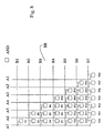
- Figure 3 represents the method of rounding by columns of the truncation error on an operation of multiplication, illustrated in a similar way as for Figure 2, i.e., showing the set of partial products.
- bit-by-bit OR operation referred to each of the columns in a window C outside the window W used for selecting the addenda of the set P to be used for the partial sums. If the result of said bit-by-bit OR operation on the addenda of each column belonging to the window C is one, one is added to the final sum.
- the window C comprises only the two columns corresponding to the most significant bits of the part that is truncated, i.e., the two columns immediately adjacent to the ones contained in the window W.
- Figure 4 represents the method of rounding by rows of the truncation error.
- RW which is external to the window W, be complementary to W, i.e., such that (W)U(RW) is equal to the totality of the partial products.
- the multiplication method that uses partial sums of the partial products can in turn perform said operation . of partial sum by rows or by columns, the partial sum by rows being the fastest.
- the technique proposed herein is not the best in terms of speed.
- the possible use in an architecture of a pipeline type, which enables calculation of more than one product for each cycle, enables an improvement of performance in terms of speed for the applications in which this factor is particularly significant.
- Figure 5 illustrates a first example of multiplication device implementing the method for multiplication of floating-point numbers according to the invention.
- the reference number 1000 designates a multiplication unit, which receives at its inputs the numbers FN1 and FN2.
- the multiplication unit 1000 is made up of a number of modules, namely:
- the module 1001 simply performs a XOR operation on the sign bits SN1 and SN2.
- FIG 6 represents in detail the diagram of operation of the adder that implements the module 1002.
- Indicated by EN10...EN15 are the bits of the exponent EN1 and by EN20...EN25 are the bits of the exponent EN2.
- the bit S7 is sent negated to the module 1002 so as to be used for subtracting one from the sum of EN1 and EN2.
- a further exception module 1100 can be associated to the multiplication unit 1000 represented in Figure 5 in order to solve the cases in which the operand is an infinite value or a NaN value.
- the exception module 1100 is connected in parallel to the unit 1000, as shown in Figure 7, and their outputs are sent to a multiplexer MUX1, which selects the output according to the value of an exception signal EXC supplies by the exception module 1100 itself.
- the exception module 1100 is obtained via a combinatorial network, which verifies whether the numbers FN1 and FN2 are infinite values or NaN.
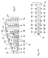
- Figure 12 represents the block diagram of a multiplication module 100, in which designated by 10 is a block representing a matrix logic circuit for generating partial products, which receives at input bits A7...A1 of the mantissa MN1 and bits B1....B7 of the mantissa MN2 and supplies at output, to a block 30, addenda of the partial products P1...P28.
- the block 30 is designed to perform operations of partial sum on the addenda of the partial products P1...P28 and supplies at output partial sums S0..S7 to a block 40, which is designed to perform a correction step of the partial sums S7...S0 and supplies corrected partial sums R0...R7.
- Figure 8 represents the matrix logic circuit 10, which is designed to generate the addenda of the partial products P1...P28.
- the circuit 10 receives at input the bits A7...A1 of the mantissa MN1 on the columns and the bits B7...B1 of the mantissa MN2 on the rows. Columns and rows of the circuit 10 form the inputs of AND gates that supply the products P1...P28.
- the circuit 10 is conceived with an already conveniently reduced structure, i.e., provided just with the gates necessary for calculating the addenda of the partial products comprised in the subset identified by said window W.
- Figure 9 represents the block 30, which is basically formed by a parallel adder structure comprising a plurality of adders designated by the references 22 to 27 for performing the sum by columns of the addenda of the partial products P1...P28 supplied by the circuit 10.
- the adder 22 is a modulo-2 adder, which sums two bits at input and supplies two bits at output.
- the adder 23 is a modulo-3 adder, which sums three bits at input and supplies two bits at output.
- the adder 24 is a modulo-4 adder, which sums four bits at input and supplies three bits at output.
- the adder 25 is a modulo-5 adder, which sums five bits at input and supplies three bits at output.
- the adder 26 is a modulo-6 adder, which sums six bits at input and supplies three bits at output.
- the adder 27 is a modulo-7 adder, which sums seven bits at input and supplies three bits at output.
- Each adder sends its own output bits, i.e., the result of the operation of addition on the addenda of the partial products, at input to the adjacent adders, except for the output least significant bit or LSB, which is supplied as the result of the operation of partial addition.
- the modulo-4 adder 24 which has three output bits, supplies the first two significant bits respectively to the adder 23 and to the adder 22, whilst the least significant bit constitutes the partial sum S5.
- each adder 22 to 27 operates on the addenda of the partial products lying on a diagonal of the matrix of the circuit 10.
- the modulo-7 adder 27 operates on the addenda P1, P3, P6, P10, P15, P21, P28 for supplying the partial sum S0, whilst S6 is supplied by the modulo-3 adder 23 which operates just on the product P22, and the modulo-2 adder 22 does not have at its input addenda of partial products, but only the bits at output from the adders 23 and 24.
- the partial sum S7 has also the function of driving the calculation of the exponent in the module 1001.
- the partial sums S7...S0 are sent to one-bit multiplexers 41 belonging to a block 40, represented in Figure 10, which carries out a correction on the partial sums S7...S0 to supply the corrected result R7...R0 according to the value of the sum S7.
- Said block 40 is hence a simple one-bit multiplexer controlled by the bit of the partial sum S7. If the partial sum S7 is equal to zero, certainly the partial sum S6 has the value one; hence, the block 40 performs a shift to the left of the bits S7...S0. If the partial sum S7 has the value one, then the result is left unchanged.
- Figure 11 represents, by means of a schematic representation of its adder network, a module 50, alternative to the circuit 30 used in the module 100, which performs the sum of the partial products by rows.
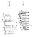
- Figure 13 designated by 110 is a module that, with respect to the module 100 of Figure 12, implements the method of rounding by columns.
- Said module 110 comprises the block 10, which receives the bits A7...A0 and B7...B0 and supplies the addenda of the partial products P1...P28 to a block 60, which, like the block 30, carries out the partial sums.
- the bits A7...A0 and B7...B0 are however sent in parallel also to a block 70, illustrated in detail in Figure 19.
- the block 70 performs the operation of rounding on the columns, as mentioned with reference to Figure 2, i.e., performs a bit-by-bit OR operation on the columns and supplies a carry signal CR to the module 60 that performs the partial sums.
- the block 70 comprises a first array of AND gates for calculating the addenda that form the two columns selected in the subset identified by the window C in Figure 3.
- the module 60 represented in Figure 14, comprises, set in cascaded fashion, a modulo-8 adder 28, with eight inputs and three outputs, three modulo-7 adders 27 and the adders 25, 24, 23 and 22. Supplied to the modulo-8 adder are the addenda P1, P3, P6, P10, P15, P21, P28 originated on the longest diagonal of the matrix of the circuit 10, and the carry signal CR coming from block 70 is moreover supplied to the remaining input.
- FIG 15 designated by the reference 80 is the detailed diagram of a circuit, alternative to the block 60, which carries out the partial sums on the partial products proceeding by rows.
- Designated by 120 in Figure 16 is a module that adopts the method of rounding by rows.
- the module 120 hence comprises the circuit 10 for generation of the addenda of the partial products P1...P28, which are supplied to a block 87, which performs the partial sums by columns.
- the block 87 receives also a bus C6...C0 of carry signals supplied by an appropriate block 85, which is used to calculate the partial sums S7...S0 rounding them by rows.
- the block 87 is described in Figure 17 and comprises, connected in cascaded fashion, one after another, an adder 27, three adders 28, a further adder 27, and then the adders 26, 25,23,22.
- the unit 85 implements the bit-by-bit AND operation on the rows belonging to the subset of addenda in the window RW, as defined for the method of rounding by rows illustrated with reference to Figure 4, and supplies the values for each row in the form of the bus of carry signals C6...C0.
- the signals M0...M22 represent the 23 bits of the mantissa according to the IEEE754 representation in single precision.
- the signals E0...E7 represent the 8 bits of the exponent according to the IEEE754 representation in single precision.
- Figure 20 represents a conversion circuit 3000 from the IEEE754 format to the representation according to the invention.
- a multiplexer MUX2 which, in the case of a normalized value, receives at input the mantissa bits M0...M6 appropriately associated to the value one in a block 3001.
- the bits M7...M22 in said block 3001 are ignored in so far as, in the implementation of the method according to the invention described herein, for the mantissa MN only eight bits are used.
- the mantissa to be converted is sent to a search unit 2004, which searches for the first one present in the string of bits that constitutes the mantissa and supplies a position 1 thereof in the string to a group shifter 2005, which extracts the first 8 bits starting from said position 1 and sends them to the multiplexer MUX2.
- the output of the multiplexer MUX2 is driven by the output of a block 2001 represented in detail in Figure 21, which receives at input the bits of mantissa M0...M22 and exponent E0...E7 and is designed to establish whether the floating-point number f is normalized or denormalized.
- the logic value 0 at output from the circuit 2001 means that the number is denormalized, whilst the logic value 1 at output from the circuit 2001 means that the number is normalized.
- the index 1 which indicates the position in the bit string that constitutes the mantissa is moreover sent to a circuit 2000 for conversion of the exponent.
- the conversion circuit 2000 is represented in Figure 22 and comprises a module 2003 for the conversion of the exponent, the output of which is sent to a multiplexer MUX3 together with the output of a block 2010, which subtracts from the value of the exponent the index I found by the search unit 2004.
- the unit 2003 for the conversion of the exponent is represented in Figure 23 and consists basically of an adder that receives at input the exponent and the bias value.
- the multiplexer MUX3 is driven, for selecting between a normalized and a denormalized number, by a block 2001 that establishes whether the number to be converted is normalized or denormalized.
- Figure 24 represents a circuit 3003 for conversion of the exponent of completely normalized numbers into the IEEE754 standard.
- the circuit 3003 comprises a block 2003, basically an adder, which receives at input the value of the base exponent exp and of bias, in this case positive.
- a multiplexer MUX4 which operates under the control of the circuit 2002, which likewise receives the exponent, chooses the output of the block 2003 or else a value zero in the case of a denormalized number.
- Figure 25 represents a circuit 3004 for conversion of the mantissa of completely normalized numbers FN into the IEEE754 standard.
- the above circuit 3004 comprises a unit 2003, which receives at input the exponent exp and a bias value equal to -126.
- a completely normalized number with exponent smaller than or equal to -126 is converted into the IEEE754 denormalized form: i.e., the exponent has the value -126, and the mantissa MN is scaled via a shift to the right by a number of positions equal to the difference between the exponent value and 126, by means of a shift-to-the-right unit 2006.
- the bit in the position MN7 is omitted, in so far as it is implicit.
- the 23 bits of the IEEE754 mantissa are formed with the MN-1 bits of the completely normalized number FN, leaving the remaining 23-MN+1 bits at zero and decrementing the exponent by one.
- a multiplexer MUX5 driven by a unit 2002 then selects the normalized or denormalized value.
- Figure 26 represents the percentage error according to the width of the window W.
- the line NR indicates the line obtained using the method according to the invention without rounding, the line RI corresponds to the method with rounding by columns, and the line RII corresponds to the method with rounding by rows.
- Figure 27 represents the maximum percentage error according to the number MA of bits used for representing the mantissa MN in a multiplication unit for floating-point numbers according to the technique described herein.
- bit-error rate of the system remains in any case within the threshold of -3dB.
- Simulations of this sort point towards a number NE of bits equal to 6 for the exponent EN.
Landscapes
- Engineering & Computer Science (AREA)
- General Physics & Mathematics (AREA)
- Physics & Mathematics (AREA)
- Mathematical Optimization (AREA)
- Computing Systems (AREA)
- Mathematical Analysis (AREA)
- Computational Mathematics (AREA)
- Pure & Applied Mathematics (AREA)
- Theoretical Computer Science (AREA)
- Nonlinear Science (AREA)
- General Engineering & Computer Science (AREA)
- Complex Calculations (AREA)
- Mobile Radio Communication Systems (AREA)
Applications Claiming Priority (2)
| Application Number | Priority Date | Filing Date | Title |
|---|---|---|---|
| IT001081A ITTO20021081A1 (it) | 2002-12-13 | 2002-12-13 | Procedimento e dispositivo per la moltiplicazione in virgola mobile, relativo prodotto informatico. |
| ITTO20021081 | 2002-12-13 |
Publications (2)
| Publication Number | Publication Date |
|---|---|
| EP1429239A2 true EP1429239A2 (de) | 2004-06-16 |
| EP1429239A3 EP1429239A3 (de) | 2006-06-14 |
Family
ID=32321458
Family Applications (1)
| Application Number | Title | Priority Date | Filing Date |
|---|---|---|---|
| EP03027629A Withdrawn EP1429239A3 (de) | 2002-12-13 | 2003-12-02 | Gleitkommamultiplizierung |
Country Status (3)
| Country | Link |
|---|---|
| US (1) | US7330867B2 (de) |
| EP (1) | EP1429239A3 (de) |
| IT (1) | ITTO20021081A1 (de) |
Families Citing this family (4)
| Publication number | Priority date | Publication date | Assignee | Title |
|---|---|---|---|---|
| US8433736B2 (en) * | 2009-02-27 | 2013-04-30 | George Mason Intellectual Properties, Inc. | Scalable Montgomery multiplication architecture |
| CN105867876A (zh) * | 2016-03-28 | 2016-08-17 | 武汉芯泰科技有限公司 | 一种乘加器、乘加器阵列、数字滤波器及乘加计算方法 |
| US11294626B2 (en) | 2018-09-27 | 2022-04-05 | Intel Corporation | Floating-point dynamic range expansion |
| JP2022016795A (ja) * | 2020-07-13 | 2022-01-25 | 富士通株式会社 | 情報処理装置、情報処理プログラムおよび情報処理方法 |
Family Cites Families (5)
| Publication number | Priority date | Publication date | Assignee | Title |
|---|---|---|---|---|
| US3871578A (en) * | 1972-10-10 | 1975-03-18 | Digital Equipment Corp | Data processing system for multiplying and intergerizing floating point numbers |
| US5128889A (en) * | 1990-02-22 | 1992-07-07 | Matsushita Electric Industrial Co., Ltd. | Floating-point arithmetic apparatus with compensation for mantissa truncation |
| US6446104B1 (en) * | 1999-09-15 | 2002-09-03 | Sun Microsystems, Inc. | Double precision floating point multiplier having a 32-bit booth-encoded array multiplier |
| US7003540B2 (en) * | 2001-05-25 | 2006-02-21 | Sun Microsystems, Inc. | Floating point multiplier for delimited operands |
| US7831652B2 (en) * | 2001-05-25 | 2010-11-09 | Oracle America, Inc. | Floating point multiplier with embedded status information |
-
2002
- 2002-12-13 IT IT001081A patent/ITTO20021081A1/it unknown
-
2003
- 2003-12-02 EP EP03027629A patent/EP1429239A3/de not_active Withdrawn
- 2003-12-15 US US10/737,697 patent/US7330867B2/en not_active Expired - Lifetime
Also Published As
| Publication number | Publication date |
|---|---|
| US20040181567A1 (en) | 2004-09-16 |
| ITTO20021081A1 (it) | 2004-06-14 |
| US7330867B2 (en) | 2008-02-12 |
| EP1429239A3 (de) | 2006-06-14 |
Similar Documents
| Publication | Publication Date | Title |
|---|---|---|
| CN107168678B (zh) | 一种乘加计算装置及浮点乘加计算方法 | |
| KR101603471B1 (ko) | 디지털 신호 프로세서들에서의 신호 처리를 위한 시스템 및 방법 | |
| US8489663B2 (en) | Decimal floating-point adder with leading zero anticipation | |
| CN112130804B (zh) | 具有正确舍入的混合精度浮点数的融合乘加运算器 | |
| CN112130803B (zh) | 具有正确舍入的浮点点积运算器 | |
| RU2408057C2 (ru) | Умножитель с фиксированной точкой с предварительным насыщением | |
| Wahba et al. | Area efficient and fast combined binary/decimal floating point fused multiply add unit | |
| Tan et al. | Multiple-mode-supporting floating-point fma unit for deep learning processors | |
| US7912890B2 (en) | Method and apparatus for decimal number multiplication using hardware for binary number operations | |
| US20030028572A1 (en) | Fast single precision floating point accumulator using base 32 system | |
| KR100465371B1 (ko) | 덧셈 및 반올림 연산을 동시에 수행하는 부동 소수점alu 연산 장치 | |
| CN117873427A (zh) | 一种算术逻辑单元、运算处理方法、芯片及电子设备 | |
| CN119645346A (zh) | 一种混合精度的乘加运算硬件 | |
| CN112463113A (zh) | 浮点加法单元 | |
| CN117648959B (zh) | 支持神经网络运算的多精度操作数运算装置 | |
| CN109634555B (zh) | 一种基于注入值的浮点加法尾数快速舍入方法 | |
| JP4500358B2 (ja) | 演算処理装置および演算処理方法 | |
| CN110727412B (zh) | 一种基于掩码的混合浮点乘法低功耗控制方法及装置 | |
| EP1429239A2 (de) | Gleitkommamultiplizierung | |
| US7398289B2 (en) | Method and device for floating-point multiplication, and corresponding computer-program product | |
| KR100290906B1 (ko) | 부동소수점곱셈기에서반올림과덧셈을동시에수행하는장치및방법 | |
| CN112783470A (zh) | 一种用于执行浮点对数运算的装置和方法 | |
| Kuang et al. | Variable-latency floating-point multipliers for low-power applications | |
| Duarte et al. | Deep nibble: A 4-bit number format for efficient dnn training and inference in fpga | |
| Hakim et al. | Improved Decimal Rounding Module based on Compound Adder |
Legal Events
| Date | Code | Title | Description |
|---|---|---|---|
| PUAI | Public reference made under article 153(3) epc to a published international application that has entered the european phase |
Free format text: ORIGINAL CODE: 0009012 |
|
| AK | Designated contracting states |
Kind code of ref document: A2 Designated state(s): AT BE BG CH CY CZ DE DK EE ES FI FR GB GR HU IE IT LI LU MC NL PT RO SE SI SK TR |
|
| AX | Request for extension of the european patent |
Extension state: AL LT LV MK |
|
| PUAL | Search report despatched |
Free format text: ORIGINAL CODE: 0009013 |
|
| AK | Designated contracting states |
Kind code of ref document: A3 Designated state(s): AT BE BG CH CY CZ DE DK EE ES FI FR GB GR HU IE IT LI LU MC NL PT RO SE SI SK TR |
|
| AX | Request for extension of the european patent |
Extension state: AL LT LV MK |
|
| AKX | Designation fees paid | ||
| REG | Reference to a national code |
Ref country code: DE Ref legal event code: 8566 |
|
| STAA | Information on the status of an ep patent application or granted ep patent |
Free format text: STATUS: THE APPLICATION IS DEEMED TO BE WITHDRAWN |
|
| 18D | Application deemed to be withdrawn |
Effective date: 20061215 |