EP1429019A1 - Electromagnetic fuel injector for an internal combustion engine with a monolithic tubular member - Google Patents
Electromagnetic fuel injector for an internal combustion engine with a monolithic tubular member Download PDFInfo
- Publication number
- EP1429019A1 EP1429019A1 EP03104649A EP03104649A EP1429019A1 EP 1429019 A1 EP1429019 A1 EP 1429019A1 EP 03104649 A EP03104649 A EP 03104649A EP 03104649 A EP03104649 A EP 03104649A EP 1429019 A1 EP1429019 A1 EP 1429019A1
- Authority
- EP
- European Patent Office
- Prior art keywords
- injector
- armature
- electromagnetic actuator
- shutter
- valve
- Prior art date
- Legal status (The legal status is an assumption and is not a legal conclusion. Google has not performed a legal analysis and makes no representation as to the accuracy of the status listed.)
- Granted
Links
Images

Classifications
-
- F—MECHANICAL ENGINEERING; LIGHTING; HEATING; WEAPONS; BLASTING
- F02—COMBUSTION ENGINES; HOT-GAS OR COMBUSTION-PRODUCT ENGINE PLANTS
- F02M—SUPPLYING COMBUSTION ENGINES IN GENERAL WITH COMBUSTIBLE MIXTURES OR CONSTITUENTS THEREOF
- F02M61/00—Fuel-injectors not provided for in groups F02M39/00 - F02M57/00 or F02M67/00
- F02M61/16—Details not provided for in, or of interest apart from, the apparatus of groups F02M61/02 - F02M61/14
- F02M61/166—Selection of particular materials
-
- F—MECHANICAL ENGINEERING; LIGHTING; HEATING; WEAPONS; BLASTING
- F02—COMBUSTION ENGINES; HOT-GAS OR COMBUSTION-PRODUCT ENGINE PLANTS
- F02M—SUPPLYING COMBUSTION ENGINES IN GENERAL WITH COMBUSTIBLE MIXTURES OR CONSTITUENTS THEREOF
- F02M51/00—Fuel-injection apparatus characterised by being operated electrically
- F02M51/06—Injectors peculiar thereto with means directly operating the valve needle
- F02M51/061—Injectors peculiar thereto with means directly operating the valve needle using electromagnetic operating means
- F02M51/0625—Injectors peculiar thereto with means directly operating the valve needle using electromagnetic operating means characterised by arrangement of mobile armatures
- F02M51/0664—Injectors peculiar thereto with means directly operating the valve needle using electromagnetic operating means characterised by arrangement of mobile armatures having a cylindrically or partly cylindrically shaped armature, e.g. entering the winding; having a plate-shaped or undulated armature entering the winding
- F02M51/0667—Injectors peculiar thereto with means directly operating the valve needle using electromagnetic operating means characterised by arrangement of mobile armatures having a cylindrically or partly cylindrically shaped armature, e.g. entering the winding; having a plate-shaped or undulated armature entering the winding the armature acting as a valve or having a short valve body attached thereto
-
- F—MECHANICAL ENGINEERING; LIGHTING; HEATING; WEAPONS; BLASTING
- F02—COMBUSTION ENGINES; HOT-GAS OR COMBUSTION-PRODUCT ENGINE PLANTS
- F02M—SUPPLYING COMBUSTION ENGINES IN GENERAL WITH COMBUSTIBLE MIXTURES OR CONSTITUENTS THEREOF
- F02M61/00—Fuel-injectors not provided for in groups F02M39/00 - F02M57/00 or F02M67/00
- F02M61/16—Details not provided for in, or of interest apart from, the apparatus of groups F02M61/02 - F02M61/14
-
- Y—GENERAL TAGGING OF NEW TECHNOLOGICAL DEVELOPMENTS; GENERAL TAGGING OF CROSS-SECTIONAL TECHNOLOGIES SPANNING OVER SEVERAL SECTIONS OF THE IPC; TECHNICAL SUBJECTS COVERED BY FORMER USPC CROSS-REFERENCE ART COLLECTIONS [XRACs] AND DIGESTS
- Y10—TECHNICAL SUBJECTS COVERED BY FORMER USPC
- Y10S—TECHNICAL SUBJECTS COVERED BY FORMER USPC CROSS-REFERENCE ART COLLECTIONS [XRACs] AND DIGESTS
- Y10S239/00—Fluid sprinkling, spraying, and diffusing
- Y10S239/90—Electromagnetically actuated fuel injector having ball and seat type valve
Landscapes
- Engineering & Computer Science (AREA)
- Chemical & Material Sciences (AREA)
- Combustion & Propulsion (AREA)
- Mechanical Engineering (AREA)
- General Engineering & Computer Science (AREA)
- Physics & Mathematics (AREA)
- Electromagnetism (AREA)
- Fuel-Injection Apparatus (AREA)
Abstract
Description
Claims (11)
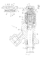
- An electromagnetic fuel injector (1) for an internal combustion engine; the injector (1) comprising a main body (4) having a central cylindrical cavity (5) adapted to act as a duct for the fuel, a valve (6) which is disposed to close an end of the central cylindrical cavity (5) in order to regulate the flow of fuel and is provided with a moving shutter (9), and an electromagnetic actuator (13) which is provided with a coil (15) disposed coaxially about the central cylindrical cavity (5), a fixed armature (17) of ferromagnetic material, and a moving armature (18) of ferromagnetic material mechanically connected to the shutter (9) and adapted to be magnetically attracted by the fixed armature (17) against the action of a spring (19); the injector (1) further comprising a monolithic tubular member (24) which is made from ferromagnetic material, is disposed coaxially within the central cylindrical cavity (5) of the main body (4) and houses the fixed armature (17) and the moving armature (18) of the electromagnetic actuator (13); the injector (1) being characterised in that the fixed armature (17) and the moving armature (18) are made from a first ferromagnetic material, while the tubular member (24) is made from a second ferromagnetic material having a lower magnetic permeability than the first ferromagnetic material.
- An injector (1) as claimed in claim 1, in which the monolithic tubular member (24) has an axial length substantially equal to the axial length of the central cylindrical cavity (5).
- An injector (1) as claimed in claim 1 or 2, in which the monolithic tubular member (24) houses the spring (19) of the electromagnetic actuator (13).
- An injector (1) as claimed in claim 3, in which the fixed armature (17) and the moving armature (18) of the electromagnetic actuator (13) have respective central holes (21, 22) which are coaxial, have the same dimension and house the spring (19) of the electromagnetic actuator (13).
- An injector (1) as claimed in claim 4, in which the spring (19) of the electromagnetic actuator (13) is compressed between the shutter (9) and a drilled abutment body (20) which is disposed in a fixed position within the central hole (21) of the fixed armature (17).
- An injector (1) as claimed in one of claims 1 to 5, in which the monolithic tubular member (24) houses the valve (6).
- An injector (1) as claimed in claim 6, in which the shutter (9) of the valve (6) is welded to a wall of the moving armature (18) of the electromagnetic actuator (13).
- An injector (1) as claimed in claim 7, in which the valve (6) comprises a valve seat (7) having a central injection hole (8), the shutter (9) comprising a plate (10) which has at least one peripheral supply hole (11) and a sealing member (12) which is circular in shape, projects from the plate (10) and is adapted to isolate the supply hole (11) from the injection hole (8) when the shutter (9) is urged to abut against the valve seat (7).
- An injector (1) as claimed in one of claims 1 to 8, comprising an atomiser coupled to the valve (6).
- An injector (1) as claimed in one of claims 1 to 9, comprising a non-return device interposed between the fixed armature (17) and the moving armature (18) of the electromagnetic actuator (13).
- An injector (1) as claimed in one of claims 1 to 10, wherein between the section of the tubular member (24) and the section of the fixed armature (17) and the moving armature (18) there is a ratio of 1:4.
Applications Claiming Priority (2)
| Application Number | Priority Date | Filing Date | Title |
|---|---|---|---|
| IT000778A ITBO20020778A1 (en) | 2002-12-12 | 2002-12-12 | ELECTROMAGNETIC FUEL INJECTOR FOR AN ENGINE |
| ITBO20020778 | 2002-12-12 |
Publications (2)
| Publication Number | Publication Date |
|---|---|
| EP1429019A1 true EP1429019A1 (en) | 2004-06-16 |
| EP1429019B1 EP1429019B1 (en) | 2007-06-13 |
Family
ID=32321406
Family Applications (1)
| Application Number | Title | Priority Date | Filing Date |
|---|---|---|---|
| EP03104649A Expired - Fee Related EP1429019B1 (en) | 2002-12-12 | 2003-12-11 | Electromagnetic fuel injector for an internal combustion engine with a monolithic tubular member |
Country Status (6)
| Country | Link |
|---|---|
| US (1) | US6932284B2 (en) |
| EP (1) | EP1429019B1 (en) |
| BR (1) | BR0306165A (en) |
| DE (1) | DE60314359T2 (en) |
| ES (1) | ES2287412T3 (en) |
| IT (1) | ITBO20020778A1 (en) |
Cited By (4)
| Publication number | Priority date | Publication date | Assignee | Title |
|---|---|---|---|---|
| WO2006010665A1 (en) | 2004-07-26 | 2006-02-02 | Robert Bosch Gmbh | Fuel injection valve |
| EP1895218A1 (en) * | 2006-09-04 | 2008-03-05 | Magneti Marelli Powertrain S.p.A. | Shut-off valve for controlling the flow rate of a fuel pump for an internal combustion engine |
| EP2221468A1 (en) * | 2009-02-20 | 2010-08-25 | Continental Automotive GmbH | Fluid injector |
| US7854400B2 (en) * | 2004-09-28 | 2010-12-21 | Robert Bosch Gmbh | Fuel injector |
Families Citing this family (3)
| Publication number | Priority date | Publication date | Assignee | Title |
|---|---|---|---|---|
| JP4161217B2 (en) * | 2003-12-26 | 2008-10-08 | 株式会社デンソー | Fuel injection valve |
| JP4734351B2 (en) * | 2008-01-28 | 2011-07-27 | 日立オートモティブシステムズ株式会社 | Fuel injection valve and internal combustion engine |
| GB0904645D0 (en) * | 2009-03-19 | 2009-04-29 | Delphi Tech Inc | Actuator arrangement |
Citations (4)
| Publication number | Priority date | Publication date | Assignee | Title |
|---|---|---|---|---|
| WO1994019599A1 (en) * | 1993-02-16 | 1994-09-01 | Siemens Automotive L.P. | Fuel injector |
| JP2002206468A (en) * | 2001-01-12 | 2002-07-26 | Aisan Ind Co Ltd | Solenoid fuel injection valve |
| US20020130206A1 (en) * | 2001-03-16 | 2002-09-19 | Unisia Jecs Corporation | Fuel injector and method of manufacturing the same |
| US6464153B1 (en) * | 2000-10-12 | 2002-10-15 | Delphi Technologies, Inc. | Fuel injector having a molded shroud formed of a structural adhesive polymer |
Family Cites Families (2)
| Publication number | Priority date | Publication date | Assignee | Title |
|---|---|---|---|---|
| JP3505054B2 (en) * | 1997-01-17 | 2004-03-08 | 株式会社日立製作所 | Injector |
| US6431474B2 (en) * | 1999-05-26 | 2002-08-13 | Siemens Automotive Corporation | Compressed natural gas fuel injector having magnetic pole face flux director |
-
2002
- 2002-12-12 IT IT000778A patent/ITBO20020778A1/en unknown
-
2003
- 2003-12-11 US US10/732,810 patent/US6932284B2/en not_active Expired - Fee Related
- 2003-12-11 DE DE60314359T patent/DE60314359T2/en not_active Expired - Lifetime
- 2003-12-11 ES ES03104649T patent/ES2287412T3/en not_active Expired - Lifetime
- 2003-12-11 EP EP03104649A patent/EP1429019B1/en not_active Expired - Fee Related
- 2003-12-12 BR BR0306165-5A patent/BR0306165A/en not_active Application Discontinuation
Patent Citations (4)
| Publication number | Priority date | Publication date | Assignee | Title |
|---|---|---|---|---|
| WO1994019599A1 (en) * | 1993-02-16 | 1994-09-01 | Siemens Automotive L.P. | Fuel injector |
| US6464153B1 (en) * | 2000-10-12 | 2002-10-15 | Delphi Technologies, Inc. | Fuel injector having a molded shroud formed of a structural adhesive polymer |
| JP2002206468A (en) * | 2001-01-12 | 2002-07-26 | Aisan Ind Co Ltd | Solenoid fuel injection valve |
| US20020130206A1 (en) * | 2001-03-16 | 2002-09-19 | Unisia Jecs Corporation | Fuel injector and method of manufacturing the same |
Non-Patent Citations (1)
| Title |
|---|
| PATENT ABSTRACTS OF JAPAN vol. 2002, no. 11 6 November 2002 (2002-11-06) * |
Cited By (6)
| Publication number | Priority date | Publication date | Assignee | Title |
|---|---|---|---|---|
| WO2006010665A1 (en) | 2004-07-26 | 2006-02-02 | Robert Bosch Gmbh | Fuel injection valve |
| JP2008507660A (en) * | 2004-07-26 | 2008-03-13 | ローベルト ボツシユ ゲゼルシヤフト ミツト ベシユレンクテル ハフツング | Fuel injection valve |
| US7854400B2 (en) * | 2004-09-28 | 2010-12-21 | Robert Bosch Gmbh | Fuel injector |
| EP1895218A1 (en) * | 2006-09-04 | 2008-03-05 | Magneti Marelli Powertrain S.p.A. | Shut-off valve for controlling the flow rate of a fuel pump for an internal combustion engine |
| US7814886B2 (en) | 2006-09-04 | 2010-10-19 | Magneti Marelli Powertrain S.P.A. | Shut-off valve for controlling the flow rate of a fuel pump for an internal combustion engine |
| EP2221468A1 (en) * | 2009-02-20 | 2010-08-25 | Continental Automotive GmbH | Fluid injector |
Also Published As
| Publication number | Publication date |
|---|---|
| ITBO20020778A1 (en) | 2004-06-13 |
| DE60314359T2 (en) | 2008-02-14 |
| DE60314359D1 (en) | 2007-07-26 |
| EP1429019B1 (en) | 2007-06-13 |
| US20040169095A1 (en) | 2004-09-02 |
| BR0306165A (en) | 2004-08-31 |
| ES2287412T3 (en) | 2007-12-16 |
| US6932284B2 (en) | 2005-08-23 |
Similar Documents
| Publication | Publication Date | Title |
|---|---|---|
| JP3625831B2 (en) | Improved basin mover for fuel injectors | |
| US4546339A (en) | Pole structure for a polarized electromagnet | |
| JP4603749B2 (en) | Fuel injection valve | |
| US5141164A (en) | Fuel injector | |
| US7278594B2 (en) | Fuel injector | |
| US5645226A (en) | Solenoid motion initiator | |
| JP2006022721A (en) | Fuel injection valve | |
| EP2436908A1 (en) | Valve assembly for an injection valve and injection valve | |
| KR100202218B1 (en) | Electromagnetically operated fuel-injection valve | |
| JPH056071B2 (en) | ||
| TWI231341B (en) | Electromagnetic fuel injection valve | |
| US6932284B2 (en) | Electromagnetic fuel injector for an internal combustion engine with a monolithic tubular member | |
| KR100878131B1 (en) | Fuel injection valve | |
| JPH0457870B2 (en) | ||
| US20110100332A1 (en) | Electromagnetically actuable valve | |
| EP0616664A1 (en) | Dynamic flow calibration of a fuel injector by selective diversion of magnetic flux from the working gap. | |
| US10253739B2 (en) | Fuel injection valve for an internal combustion engine | |
| KR950001333B1 (en) | Electromagnetically actuable fuel injection valve | |
| JP2004506131A (en) | Fuel injection valve | |
| JPS63195377A (en) | Fuel injection valve | |
| EP0294406A1 (en) | Fuel injector | |
| JP2006307831A (en) | Fuel injection valve | |
| JP3945357B2 (en) | Fuel injection device | |
| JP2002115620A (en) | Device and method for setting injector lift | |
| JP5114571B2 (en) | Solenoid operated valve |
Legal Events
| Date | Code | Title | Description |
|---|---|---|---|
| PUAI | Public reference made under article 153(3) epc to a published international application that has entered the european phase |
Free format text: ORIGINAL CODE: 0009012 |
|
| AK | Designated contracting states |
Kind code of ref document: A1 Designated state(s): AT BE BG CH CY CZ DE DK EE ES FI FR GB GR HU IE IT LI LU MC NL PT RO SE SI SK TR |
|
| AX | Request for extension of the european patent |
Extension state: AL LT LV MK |
|
| 17P | Request for examination filed |
Effective date: 20041004 |
|
| AKX | Designation fees paid |
Designated state(s): DE ES FR GB SE |
|
| 17Q | First examination report despatched |
Effective date: 20060831 |
|
| GRAP | Despatch of communication of intention to grant a patent |
Free format text: ORIGINAL CODE: EPIDOSNIGR1 |
|
| GRAS | Grant fee paid |
Free format text: ORIGINAL CODE: EPIDOSNIGR3 |
|
| GRAA | (expected) grant |
Free format text: ORIGINAL CODE: 0009210 |
|
| AK | Designated contracting states |
Kind code of ref document: B1 Designated state(s): DE ES FR GB SE |
|
| REG | Reference to a national code |
Ref country code: GB Ref legal event code: FG4D |
|
| REF | Corresponds to: |
Ref document number: 60314359 Country of ref document: DE Date of ref document: 20070726 Kind code of ref document: P |
|
| REG | Reference to a national code |
Ref country code: SE Ref legal event code: TRGR |
|
| ET | Fr: translation filed | ||
| REG | Reference to a national code |
Ref country code: ES Ref legal event code: FG2A Ref document number: 2287412 Country of ref document: ES Kind code of ref document: T3 |
|
| PLBE | No opposition filed within time limit |
Free format text: ORIGINAL CODE: 0009261 |
|
| STAA | Information on the status of an ep patent application or granted ep patent |
Free format text: STATUS: NO OPPOSITION FILED WITHIN TIME LIMIT |
|
| 26N | No opposition filed |
Effective date: 20080314 |
|
| PGFP | Annual fee paid to national office [announced via postgrant information from national office to epo] |
Ref country code: ES Payment date: 20091203 Year of fee payment: 7 Ref country code: SE Payment date: 20091125 Year of fee payment: 7 |
|
| PGFP | Annual fee paid to national office [announced via postgrant information from national office to epo] |
Ref country code: GB Payment date: 20091125 Year of fee payment: 7 |
|
| GBPC | Gb: european patent ceased through non-payment of renewal fee |
Effective date: 20101211 |
|
| REG | Reference to a national code |
Ref country code: SE Ref legal event code: EUG |
|
| PG25 | Lapsed in a contracting state [announced via postgrant information from national office to epo] |
Ref country code: SE Free format text: LAPSE BECAUSE OF NON-PAYMENT OF DUE FEES Effective date: 20101212 |
|
| PG25 | Lapsed in a contracting state [announced via postgrant information from national office to epo] |
Ref country code: GB Free format text: LAPSE BECAUSE OF NON-PAYMENT OF DUE FEES Effective date: 20101211 |
|
| REG | Reference to a national code |
Ref country code: ES Ref legal event code: FD2A Effective date: 20120220 |
|
| PG25 | Lapsed in a contracting state [announced via postgrant information from national office to epo] |
Ref country code: ES Free format text: LAPSE BECAUSE OF NON-PAYMENT OF DUE FEES Effective date: 20101212 |
|
| REG | Reference to a national code |
Ref country code: FR Ref legal event code: PLFP Year of fee payment: 13 |
|
| PGFP | Annual fee paid to national office [announced via postgrant information from national office to epo] |
Ref country code: DE Payment date: 20151119 Year of fee payment: 13 |
|
| PGFP | Annual fee paid to national office [announced via postgrant information from national office to epo] |
Ref country code: FR Payment date: 20151123 Year of fee payment: 13 |
|
| REG | Reference to a national code |
Ref country code: DE Ref legal event code: R119 Ref document number: 60314359 Country of ref document: DE |
|
| REG | Reference to a national code |
Ref country code: FR Ref legal event code: ST Effective date: 20170831 |
|
| PG25 | Lapsed in a contracting state [announced via postgrant information from national office to epo] |
Ref country code: FR Free format text: LAPSE BECAUSE OF NON-PAYMENT OF DUE FEES Effective date: 20170102 |
|
| PG25 | Lapsed in a contracting state [announced via postgrant information from national office to epo] |
Ref country code: DE Free format text: LAPSE BECAUSE OF NON-PAYMENT OF DUE FEES Effective date: 20170701 |