EP1429016A1 - Methods and apparatus for operating gas turbine engines - Google Patents
Methods and apparatus for operating gas turbine engines Download PDFInfo
- Publication number
- EP1429016A1 EP1429016A1 EP03257760A EP03257760A EP1429016A1 EP 1429016 A1 EP1429016 A1 EP 1429016A1 EP 03257760 A EP03257760 A EP 03257760A EP 03257760 A EP03257760 A EP 03257760A EP 1429016 A1 EP1429016 A1 EP 1429016A1
- Authority
- EP
- European Patent Office
- Prior art keywords
- detonation
- tube
- pulse
- tubes
- chamber
- Prior art date
- Legal status (The legal status is an assumption and is not a legal conclusion. Google has not performed a legal analysis and makes no representation as to the accuracy of the status listed.)
- Granted
Links
- 238000000034 method Methods 0.000 title claims abstract description 12
- 238000005474 detonation Methods 0.000 claims abstract description 120
- 239000000446 fuel Substances 0.000 claims abstract description 17
- 239000000203 mixture Substances 0.000 claims abstract description 13
- 239000000567 combustion gas Substances 0.000 description 13
- 238000010304 firing Methods 0.000 description 12
- 239000007789 gas Substances 0.000 description 11
- 238000011144 upstream manufacturing Methods 0.000 description 6
- 230000001419 dependent effect Effects 0.000 description 1
- 230000003252 repetitive effect Effects 0.000 description 1
- 238000000926 separation method Methods 0.000 description 1
Images


Classifications
-
- F—MECHANICAL ENGINEERING; LIGHTING; HEATING; WEAPONS; BLASTING
- F23—COMBUSTION APPARATUS; COMBUSTION PROCESSES
- F23C—METHODS OR APPARATUS FOR COMBUSTION USING FLUID FUEL OR SOLID FUEL SUSPENDED IN A CARRIER GAS OR AIR
- F23C15/00—Apparatus in which combustion takes place in pulses influenced by acoustic resonance in a gas mass
-
- F—MECHANICAL ENGINEERING; LIGHTING; HEATING; WEAPONS; BLASTING
- F02—COMBUSTION ENGINES; HOT-GAS OR COMBUSTION-PRODUCT ENGINE PLANTS
- F02C—GAS-TURBINE PLANTS; AIR INTAKES FOR JET-PROPULSION PLANTS; CONTROLLING FUEL SUPPLY IN AIR-BREATHING JET-PROPULSION PLANTS
- F02C5/00—Gas-turbine plants characterised by the working fluid being generated by intermittent combustion
- F02C5/02—Gas-turbine plants characterised by the working fluid being generated by intermittent combustion characterised by the arrangement of the combustion chamber in the chamber in the plant
-
- F—MECHANICAL ENGINEERING; LIGHTING; HEATING; WEAPONS; BLASTING
- F02—COMBUSTION ENGINES; HOT-GAS OR COMBUSTION-PRODUCT ENGINE PLANTS
- F02K—JET-PROPULSION PLANTS
- F02K3/00—Plants including a gas turbine driving a compressor or a ducted fan
- F02K3/08—Plants including a gas turbine driving a compressor or a ducted fan with supplementary heating of the working fluid; Control thereof
-
- F—MECHANICAL ENGINEERING; LIGHTING; HEATING; WEAPONS; BLASTING
- F02—COMBUSTION ENGINES; HOT-GAS OR COMBUSTION-PRODUCT ENGINE PLANTS
- F02K—JET-PROPULSION PLANTS
- F02K7/00—Plants in which the working fluid is used in a jet only, i.e. the plants not having a turbine or other engine driving a compressor or a ducted fan; Control thereof
- F02K7/02—Plants in which the working fluid is used in a jet only, i.e. the plants not having a turbine or other engine driving a compressor or a ducted fan; Control thereof the jet being intermittent, i.e. pulse-jet
- F02K7/075—Plants in which the working fluid is used in a jet only, i.e. the plants not having a turbine or other engine driving a compressor or a ducted fan; Control thereof the jet being intermittent, i.e. pulse-jet with multiple pulse-jet engines
-
- F—MECHANICAL ENGINEERING; LIGHTING; HEATING; WEAPONS; BLASTING
- F23—COMBUSTION APPARATUS; COMBUSTION PROCESSES
- F23R—GENERATING COMBUSTION PRODUCTS OF HIGH PRESSURE OR HIGH VELOCITY, e.g. GAS-TURBINE COMBUSTION CHAMBERS
- F23R7/00—Intermittent or explosive combustion chambers
-
- F—MECHANICAL ENGINEERING; LIGHTING; HEATING; WEAPONS; BLASTING
- F05—INDEXING SCHEMES RELATING TO ENGINES OR PUMPS IN VARIOUS SUBCLASSES OF CLASSES F01-F04
- F05D—INDEXING SCHEME FOR ASPECTS RELATING TO NON-POSITIVE-DISPLACEMENT MACHINES OR ENGINES, GAS-TURBINES OR JET-PROPULSION PLANTS
- F05D2270/00—Control
- F05D2270/01—Purpose of the control system
- F05D2270/11—Purpose of the control system to prolong engine life
-
- Y—GENERAL TAGGING OF NEW TECHNOLOGICAL DEVELOPMENTS; GENERAL TAGGING OF CROSS-SECTIONAL TECHNOLOGIES SPANNING OVER SEVERAL SECTIONS OF THE IPC; TECHNICAL SUBJECTS COVERED BY FORMER USPC CROSS-REFERENCE ART COLLECTIONS [XRACs] AND DIGESTS
- Y02—TECHNOLOGIES OR APPLICATIONS FOR MITIGATION OR ADAPTATION AGAINST CLIMATE CHANGE
- Y02T—CLIMATE CHANGE MITIGATION TECHNOLOGIES RELATED TO TRANSPORTATION
- Y02T50/00—Aeronautics or air transport
- Y02T50/60—Efficient propulsion technologies, e.g. for aircraft
Definitions
- This invention relates generally to gas turbine engines and more particularly, to a pulse detonation system for a gas turbine engine.
- At least some known pulse detonation systems use a series of repetitive detonations within a detonation chamber to produce a high pressure exhaust. More specifically, a fuel and air mixture is periodically detonated within a plurality of tubes within the detonation chamber to create hot combustion gases which cause pressure waves to propagate at supersonic speeds within the tubes and chamber. The pressure waves compress the hot combustion gases, which increases a pressure, density, and a temperature of the gases to produce thrust as the pressure waves pass the exit of an open end of the detonation chamber.
- Pulse detonation engines typically have a higher thrust to weight ratio because they are generally smaller and weigh less than conventional gas turbine engines.
- pulse detonation engines may include fewer rotating parts, produce lower emissions, and be more fuel efficient than conventional gas turbine engines. Pulse detonation engines also may not suffer stall and startup problems that may be experienced by some known gas turbine engines because of separation in and around compressor blades within the conventional engines.
- each detonation tube has a firing frequency that is dependent upon the dynamics of detonation and a geometry of the tube.
- known pulse detonation tubes also have a dynamically varying positive pressure rise and fall in each tube as each tube repeatedly fires. The dynamic periodicity of such pressures may induce dynamic pressure loads to the pulse detonation system which may propagate from the system as acoustic pressure waves, i.e., noise.
- a method for operating a pulse detonation system.
- the method includes providing a pulse detonation chamber including a plurality of detonation tubes extending therein, and detonating a mixture of fuel and air within each detonation tube such that at least a first tube is detonated at a different time than at least a second detonation tube.
- a control system for a pulse detonation system including a plurality of detonation tubes.
- the control system includes a processor that is programmed to control detonation of a mixture of fuel and air within each detonation tube, such that at least a first detonation tube is detonated at a time that is different from a time of detonation of at least a second detonation tube.
- a pulse detonator for a pulse detonation system.
- the chamber includes an inner casing, and an outer casing that is substantially coaxial with the inner casing, and is spaced radially outwardly from the inner casing.
- the inner and outer casings define a detonation chamber therebetween.
- a plurality of detonation tubes extend at least partially within the detonation chamber. At least a portion of at least a first detonation tube is stacked radially outwardly from at least a portion of at least an adjacent second detonation tube, such that a first central axis of the first detonation tube is spaced radially outwardly from a second central axis of the adjacent second detonation tube.
- a pulse detonation system in even another aspect, includes a pulse detonator including a plurality of detonation tubes extending at least partially within the pulse detonator, and a control system that includes a processor programmed to control the detonation of a mixture of fuel and air within each detonation tube such that at least a first detonation tube is detonated at a time that is different from a time of detonation of at least a second detonation tube.
- computer means any microprocessor-based system including systems using microcontrollers, reduced instruction set circuits (RISC), application specific integrated circuits (ASICs), logic circuits, and any other circuit or processor capable of executing the functions described herein.
- RISC reduced instruction set circuits
- ASICs application specific integrated circuits
- logic circuits and any other circuit or processor capable of executing the functions described herein.
- Figure 1 is a schematic illustration of a gas turbine engine 10 including a low pressure compressor 12, a high pressure compressor 14, and a pulse detonation system 16.
- Engine 10 also includes a high pressure turbine 18, and a low pressure turbine 20.
- Compressor 12 and turbine 20 are coupled by a first shaft 24, and compressor 14 and turbine 18 are coupled by a second shaft 26.
- engine 10 is a F110/129 engine available from General Electric Aircraft Engines, Cincinnati, Ohio.
- FIG 2 is a schematic illustration of an exemplary pulse detonation system 50 for use with a gas turbine engine, for example engine 10 (shown in Figure 1).
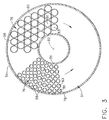
- Figure 3 is a cross-sectional view of a portion of a pulse detonator 52 for pulse detonation system 50 taken along line 3-3.
- Pulse detonation system 50 includes a pulse detonator 52 and a control system 53.
- Pulse detonator 52 includes annular outer and inner casings 54 and 56, respectively, and a plurality of detonation tubes 58.
- Outer and inner casings 54 and 56 are disposed substantially coaxially about a longitudinal centerline axis 60 of pulse detonation system 50 and are spaced radially apart such that a detonation chamber 62 is defined therebetween.
- Pulse detonator 52 includes an inlet end 64, an outlet end 66, and detonation tubes 58.
- Detonation tubes 58 extend through detonation chamber 62 along axis 60, and also extend a length 68 measured from an upstream end 70 that is adjacent chamber inlet side 64, to a downstream end 72.
- An exhaust chamber 73 is defined between detonation tube downstream ends 72 and detonator outlet end 66. Exhaust chamber 73 includes an upstream end 74 and a downstream end 75.
- Detonation tubes 58 are stacked in an array 76 within detonation chamber 62 such that a plurality of tubes 58 are spaced circumferentially around axis 60, and such that a plurality of tubes 58, or a portion of a plurality of tubes 58, are stacked radially outwardly from inner casing 56 to outer casing 54.
- detonation tubes 58 are stacked within detonation chamber 62 such that a plurality of tubes 58 are spaced circumferentially around axis 60 and such that only one tube 58 is positioned radially between inner casing 56 and outer casing 54.
- detonation tubes 58 each have a substantially circular cross-sectional geometric shape, and tubes 58 substantially occupy the space defined between inner and outer casings 56 and 54, respectively. Furthermore, as illustrated in Figure 3, tubes 58 are arranged in stacks 78 which include smaller diameter tubes 58, and stacks 80 which include larger diameter tubes 58. More specifically, in the exemplary embodiment, a central axis 81 of a first tube 58 is spaced radially outwardly from a central axis 83 of a second tube 58 that is adjacent the first tube 58.
- the number, geometric shape, configuration, and/or diameter of tubes 58 will vary depending upon the particular application, and as described below.
- detonation tubes 58 each have approximately equal diameters. In another embodiment, detonation tubes 58 include tubes of varying diameter. Furthermore, it will be understood that a length 68 of each tube 58 will vary depending upon the particular application, and as described below. For example, in one embodiment, detonation tubes 58 each include approximately equal lengths 68. In another embodiment, detonation tubes 58 include tubes of varying length 68. The examples herein described are intended as exemplary only, and are not intended to limit the number, geometric shape, configuration, diameter, and/or length 68 of detonation tubes 58.
- Control system 53 includes a computer and/or processor 82, a plurality of pressure feedback sensors 84, and a firing system 86 that is coupled to detonation tubes 58 adjacent upstream ends 70.
- firing system 86 charges each tube 58 with compressed air and fuel, and periodically detonates the mixture of fuel and air within each tube 58 to produce hot combustion gases within each tube 58 and exhaust chamber 73.
- Sensors 84 are coupled to outer casing 54 adjacent exhaust chamber 73, and measure a pressure of combustion gases within exhaust chamber 73.
- Computer 82 is electrically coupled to sensors 84 and firing system 86.
- computer 82 is a multiple-input, multiple-output, (MIMO) electronic control computer.
- control system 52 includes only one pressure feedback sensor 84.
- Firing system 86 charges each detonation tube 58 with fuel, from a fuel source (not shown), and compressed air from compressors 12 and 14 (shown in Figure 1). The mixture is detonated to produce hot combustion gases within each tube 58 that flow downstream through exhaust chamber 73 and are discharged from detonation chamber outlet end 66 towards turbines 18 and 20 (shown in Figure 1) and engine outlet 30 (shown in Figure 1).
- compressed air and fuel are mixed by firing system 86 before the mixture is supplied to each detonation tube 58.
- compressed air and fuel are each independently supplied to each detonation tube 58 and are mixed within each detonation tube 58.
- Firing system 86 does not continuously detonate the mixture within tubes 58. Rather, and as described below, firing system 86 periodically cycles the detonation of the fuel/air mixture to generate pressure waves, or pulses, that propagate through the combustion gases to facilitate increasing the pressure and temperature of the combustion gases to provide thrust.
- the pressure waves propagate downstream through tubes 58 and exhaust chamber 73.
- firing system 86 detonates the fuel air mixture in each tube 58, referred to herein as firing each tube 58, sequentially such that only a desired number of tubes 58 are fired simultaneously.
- each tube 58 is fired independently at a different time.
- a plurality of tubes 58 are fired simultaneously, and a plurality of tubes 58 are fired non-simultaneously.
- a positive-going pressure pulse is emitted that propagates downstream through exhaust chamber 73 from upstream end 74 to downstream end 75.
- Sensors 84 sense the pressure pulses from various tubes 58 within exhaust chamber 73.
- Computer 82 uses an active noise-control algorithm, determines an appropriate firing sequence for tubes 58, based on the sensed pressure pulses, such that dynamic pressure variations are reduced within exhaust chamber 73, while a high and steady pressure of combustion gases is exhausted through detonator outlet end 66 and ultimately, engine exhaust 30. More specifically, computer 82 controls firing of each tube 58 within array 76 such that low, positive pressure regions of pressure pulses are substantially aligned with high, positive pressure regions of adjacent pulses.
- Aligning adjacent pulses in such a manner facilitates reducing pressure variations.
- higher amplitude dynamic pressure variations are substantially smoothed out, causing the exhaust of combustion gases exiting exhaust chamber 73 and engine exhaust 30 to be at a substantially uniform and high pressure.
- high amplitude dynamic pressure variations are substantially contained within tubes 58 and exhaust chamber upstream end 74, such that a reduction in dynamic pressure loads is induced within system 50, and the number and intensity of acoustic pressure waves emitted by system 50 are facilitated to be reduced.
- structural failures associated with system 50 and a level of noise emitted by system 50 are facilitated to be reduced.
- each tube 58 within array 76 is fired such that high positive pressure regions of pressure pulses align with high positive regions of adjacent pressure pulses to facilitate increasing the positive pressure of the pressure pulses, and thereby increasing the pressure of the hot combustion gases exhaust from exhaust chamber 73.
- An exhaust chamber length 88 measured between the downstream end 72 of the longest tube 58 within array 76 and detonator outlet end 66, is variably selected to facilitate reducing dynamic pressures to a pre-determined level. More specifically, the geometry and configuration of detonation tubes 58 is also variably selected. For, example, in one embodiment, a greater number of smaller diameter tubes 58 may facilitate a shorter exhaust chamber length 88, than a smaller number of larger diameter tubes 58.
- the above-described pulse detonation system facilitates reducing structural failures of the system and noise produced by the system. More specifically, by aligning low positive pressure regions with high positive pressure regions of adjacent pulses, the system facilitates reducing dynamic pressure loads within the system and facilitates reducing the number and intensity of acoustic pressure waves emitted by the system.
- the above-described pulse detonation system may facilitate increasing the thrust of a pulse detonation engine by aligning high positive pressure regions with high positive regions of adjacent pressure pulses.
- a pulse detonation system is provided which may facilitate an engine that has a longer engine life, and operates with increased thrust, increased efficiency, and reduced noise.
Landscapes
- Engineering & Computer Science (AREA)
- Chemical & Material Sciences (AREA)
- Combustion & Propulsion (AREA)
- Mechanical Engineering (AREA)
- General Engineering & Computer Science (AREA)
- Fluidized-Bed Combustion And Resonant Combustion (AREA)
Abstract
Description
- This invention relates generally to gas turbine engines and more particularly, to a pulse detonation system for a gas turbine engine.
- At least some known pulse detonation systems use a series of repetitive detonations within a detonation chamber to produce a high pressure exhaust. More specifically, a fuel and air mixture is periodically detonated within a plurality of tubes within the detonation chamber to create hot combustion gases which cause pressure waves to propagate at supersonic speeds within the tubes and chamber. The pressure waves compress the hot combustion gases, which increases a pressure, density, and a temperature of the gases to produce thrust as the pressure waves pass the exit of an open end of the detonation chamber.
- Gas turbine engines producing thrust using pulse detonation systems typically have a higher thrust to weight ratio because they are generally smaller and weigh less than conventional gas turbine engines. In addition, pulse detonation engines may include fewer rotating parts, produce lower emissions, and be more fuel efficient than conventional gas turbine engines. Pulse detonation engines also may not suffer stall and startup problems that may be experienced by some known gas turbine engines because of separation in and around compressor blades within the conventional engines.
- However, pressures generated within the detonation chamber of some known pulse detonation systems may cause at least some known pulse detonation engines to be very loud and may facilitate structural failures within the engines. More specifically, each detonation tube has a firing frequency that is dependent upon the dynamics of detonation and a geometry of the tube. While conventional detonation chambers create thrust by imparting overall pressure rise the hot combustion gases, known pulse detonation tubes also have a dynamically varying positive pressure rise and fall in each tube as each tube repeatedly fires. The dynamic periodicity of such pressures may induce dynamic pressure loads to the pulse detonation system which may propagate from the system as acoustic pressure waves, i.e., noise.
- In one aspect, a method is provided for operating a pulse detonation system. The method includes providing a pulse detonation chamber including a plurality of detonation tubes extending therein, and detonating a mixture of fuel and air within each detonation tube such that at least a first tube is detonated at a different time than at least a second detonation tube.
- In another aspect, a control system is provided for a pulse detonation system including a plurality of detonation tubes. The control system includes a processor that is programmed to control detonation of a mixture of fuel and air within each detonation tube, such that at least a first detonation tube is detonated at a time that is different from a time of detonation of at least a second detonation tube.
- In yet another aspect, a pulse detonator is provided for a pulse detonation system. The chamber includes an inner casing, and an outer casing that is substantially coaxial with the inner casing, and is spaced radially outwardly from the inner casing. The inner and outer casings define a detonation chamber therebetween. A plurality of detonation tubes extend at least partially within the detonation chamber. At least a portion of at least a first detonation tube is stacked radially outwardly from at least a portion of at least an adjacent second detonation tube, such that a first central axis of the first detonation tube is spaced radially outwardly from a second central axis of the adjacent second detonation tube.
- In even another aspect, a pulse detonation system is provided that includes a pulse detonator including a plurality of detonation tubes extending at least partially within the pulse detonator, and a control system that includes a processor programmed to control the detonation of a mixture of fuel and air within each detonation tube such that at least a first detonation tube is detonated at a time that is different from a time of detonation of at least a second detonation tube.
- The invention will now be described in greater detail, by way of example, with reference to the drawings, in which:-
- Figure 1 is a schematic illustration of an exemplary gas turbine engine;
- Figure 2 is a schematic illustration of an exemplary pulse detonation system for use with the gas turbine engine shown in Figure 1; and
- Figure 3 is a cross-sectional view of a portion of a detonator shown in Figure 2 and taken alone line 3-3.
-
- The term computer, as used herein, means any microprocessor-based system including systems using microcontrollers, reduced instruction set circuits (RISC), application specific integrated circuits (ASICs), logic circuits, and any other circuit or processor capable of executing the functions described herein.
- Figure 1 is a schematic illustration of a
gas turbine engine 10 including alow pressure compressor 12, ahigh pressure compressor 14, and apulse detonation system 16.Engine 10 also includes ahigh pressure turbine 18, and alow pressure turbine 20.Compressor 12 andturbine 20 are coupled by afirst shaft 24, andcompressor 14 andturbine 18 are coupled by asecond shaft 26. In one embodiment,engine 10 is a F110/129 engine available from General Electric Aircraft Engines, Cincinnati, Ohio. - In operation, air flows through
low pressure compressor 12 from aninlet side 28 ofengine 10 and compressed air is supplied fromlow pressure compressor 12 tohigh pressure compressor 14. Compressed air is then delivered topulse detonation system 16 where it is mixed with fuel and ignited. The combustion gases are channeled frompulse detonation system 16 to driveturbines outlet 30 ofengine 10. - Figure 2 is a schematic illustration of an exemplary
pulse detonation system 50 for use with a gas turbine engine, for example engine 10 (shown in Figure 1). Figure 3 is a cross-sectional view of a portion of apulse detonator 52 forpulse detonation system 50 taken along line 3-3.Pulse detonation system 50 includes apulse detonator 52 and acontrol system 53.Pulse detonator 52 includes annular outer andinner casings detonation tubes 58. Outer andinner casings longitudinal centerline axis 60 ofpulse detonation system 50 and are spaced radially apart such that adetonation chamber 62 is defined therebetween.Pulse detonator 52 includes aninlet end 64, anoutlet end 66, anddetonation tubes 58.Detonation tubes 58 extend throughdetonation chamber 62 alongaxis 60, and also extend alength 68 measured from anupstream end 70 that is adjacentchamber inlet side 64, to adownstream end 72. Anexhaust chamber 73 is defined between detonation tubedownstream ends 72 anddetonator outlet end 66.Exhaust chamber 73 includes anupstream end 74 and adownstream end 75. -
Detonation tubes 58 are stacked in anarray 76 withindetonation chamber 62 such that a plurality oftubes 58 are spaced circumferentially aroundaxis 60, and such that a plurality oftubes 58, or a portion of a plurality oftubes 58, are stacked radially outwardly frominner casing 56 toouter casing 54. In an alternative embodiment,detonation tubes 58 are stacked withindetonation chamber 62 such that a plurality oftubes 58 are spaced circumferentially aroundaxis 60 and such that only onetube 58 is positioned radially betweeninner casing 56 andouter casing 54. - In the exemplary embodiment,
detonation tubes 58 each have a substantially circular cross-sectional geometric shape, andtubes 58 substantially occupy the space defined between inner andouter casings tubes 58 are arranged instacks 78 which includesmaller diameter tubes 58, andstacks 80 which includelarger diameter tubes 58. More specifically, in the exemplary embodiment, acentral axis 81 of afirst tube 58 is spaced radially outwardly from acentral axis 83 of asecond tube 58 that is adjacent thefirst tube 58. However, it will be understood that the number, geometric shape, configuration, and/or diameter oftubes 58 will vary depending upon the particular application, and as described below. For example, in one embodiment,detonation tubes 58 each have approximately equal diameters. In another embodiment,detonation tubes 58 include tubes of varying diameter. Furthermore, it will be understood that alength 68 of eachtube 58 will vary depending upon the particular application, and as described below. For example, in one embodiment,detonation tubes 58 each include approximatelyequal lengths 68. In another embodiment,detonation tubes 58 include tubes ofvarying length 68. The examples herein described are intended as exemplary only, and are not intended to limit the number, geometric shape, configuration, diameter, and/orlength 68 ofdetonation tubes 58. -
Control system 53 includes a computer and/orprocessor 82, a plurality ofpressure feedback sensors 84, and afiring system 86 that is coupled todetonation tubes 58 adjacentupstream ends 70. As described below,firing system 86 charges eachtube 58 with compressed air and fuel, and periodically detonates the mixture of fuel and air within eachtube 58 to produce hot combustion gases within eachtube 58 andexhaust chamber 73.Sensors 84 are coupled toouter casing 54adjacent exhaust chamber 73, and measure a pressure of combustion gases withinexhaust chamber 73.Computer 82 is electrically coupled tosensors 84 andfiring system 86. In one embodiment,computer 82 is a multiple-input, multiple-output, (MIMO) electronic control computer. In an alternative embodiment,control system 52 includes only onepressure feedback sensor 84. -
Firing system 86 charges eachdetonation tube 58 with fuel, from a fuel source (not shown), and compressed air fromcompressors 12 and 14 (shown in Figure 1). The mixture is detonated to produce hot combustion gases within eachtube 58 that flow downstream throughexhaust chamber 73 and are discharged from detonationchamber outlet end 66 towardsturbines 18 and 20 (shown in Figure 1) and engine outlet 30 (shown in Figure 1). In one embodiment, compressed air and fuel are mixed byfiring system 86 before the mixture is supplied to eachdetonation tube 58. In an alternative embodiment, compressed air and fuel are each independently supplied to eachdetonation tube 58 and are mixed within eachdetonation tube 58. -
Firing system 86 does not continuously detonate the mixture withintubes 58. Rather, and as described below, firingsystem 86 periodically cycles the detonation of the fuel/air mixture to generate pressure waves, or pulses, that propagate through the combustion gases to facilitate increasing the pressure and temperature of the combustion gases to provide thrust. The pressure waves propagate downstream throughtubes 58 andexhaust chamber 73. - The methods and systems described herein facilitate containing larger dynamic pressure variations within
tubes 58 and exhaust chamberupstream end 74, such that dynamic pressure variations are reduced within exhaust chamberdownstream end 75 as combustion gasesexit engine exhaust 30. More specifically, firingsystem 86 detonates the fuel air mixture in eachtube 58, referred to herein as firing eachtube 58, sequentially such that only a desired number oftubes 58 are fired simultaneously. In one embodiment, eachtube 58 is fired independently at a different time. In an alternative embodiment, a plurality oftubes 58 are fired simultaneously, and a plurality oftubes 58 are fired non-simultaneously. - As each
individual tube 58 fires, a positive-going pressure pulse is emitted that propagates downstream throughexhaust chamber 73 fromupstream end 74 todownstream end 75.Sensors 84 sense the pressure pulses fromvarious tubes 58 withinexhaust chamber 73.Computer 82, using an active noise-control algorithm, determines an appropriate firing sequence fortubes 58, based on the sensed pressure pulses, such that dynamic pressure variations are reduced withinexhaust chamber 73, while a high and steady pressure of combustion gases is exhausted throughdetonator outlet end 66 and ultimately,engine exhaust 30. More specifically,computer 82 controls firing of eachtube 58 withinarray 76 such that low, positive pressure regions of pressure pulses are substantially aligned with high, positive pressure regions of adjacent pulses. Aligning adjacent pulses in such a manner facilitates reducing pressure variations. Specifically, as pressure pulses propagate throughexhaust chamber 73, higher amplitude dynamic pressure variations are substantially smoothed out, causing the exhaust of combustion gases exitingexhaust chamber 73 andengine exhaust 30 to be at a substantially uniform and high pressure. Accordingly, high amplitude dynamic pressure variations are substantially contained withintubes 58 and exhaust chamberupstream end 74, such that a reduction in dynamic pressure loads is induced withinsystem 50, and the number and intensity of acoustic pressure waves emitted bysystem 50 are facilitated to be reduced. As a result, structural failures associated withsystem 50 and a level of noise emitted bysystem 50 are facilitated to be reduced. - In one embodiment, each
tube 58 withinarray 76 is fired such that high positive pressure regions of pressure pulses align with high positive regions of adjacent pressure pulses to facilitate increasing the positive pressure of the pressure pulses, and thereby increasing the pressure of the hot combustion gases exhaust fromexhaust chamber 73. - An
exhaust chamber length 88, measured between thedownstream end 72 of thelongest tube 58 withinarray 76 anddetonator outlet end 66, is variably selected to facilitate reducing dynamic pressures to a pre-determined level. More specifically, the geometry and configuration ofdetonation tubes 58 is also variably selected. For, example, in one embodiment, a greater number ofsmaller diameter tubes 58 may facilitate a shorterexhaust chamber length 88, than a smaller number oflarger diameter tubes 58. - The above-described pulse detonation system facilitates reducing structural failures of the system and noise produced by the system. More specifically, by aligning low positive pressure regions with high positive pressure regions of adjacent pulses, the system facilitates reducing dynamic pressure loads within the system and facilitates reducing the number and intensity of acoustic pressure waves emitted by the system. In addition, the above-described pulse detonation system may facilitate increasing the thrust of a pulse detonation engine by aligning high positive pressure regions with high positive regions of adjacent pressure pulses. As a result, a pulse detonation system is provided which may facilitate an engine that has a longer engine life, and operates with increased thrust, increased efficiency, and reduced noise.
Claims (9)
- A method for operating a pulse detonation system (50), said method comprising:providing a pulse detonation chamber (62) including a plurality of detonation tubes (58) extending therein; anddetonating a mixture of fuel and air within each detonation tube such that at least a first detonation tube is detonated at a different time than at least a second detonation tube.
- A method in accordance with Claim 1 wherein detonating a mixture of fuel and air within each detonation tube (58) comprises detonating at least two detonation tubes such that a region of a first pressure wave generated is substantially aligned with a region of a second pressure wave generated.
- A method in accordance with Claim 1 or 2 wherein providing a pulse detonation chamber (62) comprises providing a pulse detonation chamber including at least one detonation tube (58) that has a length (68) that is unequal to a length of at least one other detonation tube.
- A method in accordance with Claim 1 or 2 wherein providing a pulse detonation chamber (62) comprises providing a pulse detonation chamber including at least one detonation tube (58) that has a diameter that is unequal to a diameter of at least one other detonation tube.
- A method in accordance with Claim 1 or 2 wherein providing a pulse detonation chamber (62) comprises:providing a pulse detonator including an inner casing (56), and an outer casing (54) that is substantially coaxial with the inner casing and is spaced radially outwardly from the inner casing such that a pulse detonation chamber defined between the inner and outer casings; andstacking at least a portion of at least one first detonation tube (78) radially outwardly from at least a portion of at least one adjacent detonation tube (80) within the detonation chamber such that a first central axis of the first detonation tube is spaced radially outwardly from a second central axis of the adjacent detonation tube.
- A pulse detonator (52) for a pulse detonation system (50), said chamber comprising:an inner casing (56);an outer casing (54) substantially coaxial with said inner casing and spaced radially outwardly from said inner casing, said inner and outer casings defining a detonation chamber (62) therebetween; anda plurality of detonation tubes (58) extending at least partially within said detonation chamber, at least a portion of at least a first detonation tube (78) stacked radially outwardly from at least a portion of at least an adjacent second detonation tube (80) such that a first central axis of said first detonation tube is spaced radially outwardly from a second central axis of said adjacent second detonation tube.
- A pulse detonator (52) in accordance with Claim 6 wherein said inner casing (56) comprises a substantially annular casing, said outer casing (54) comprises a substantially annular casing.
- A pulse detonator (52) in accordance with Claim 6 or 7 wherein said plurality of detonation tubes (58) comprise a plurality of annular detonation tubes.
- A pulse detonator (52) in accordance with Claim 6, 7, or 8 wherein at least one detonation tube (5i8) comprises a length (68) that is unequal to a length of at least one other detonation tube.
Applications Claiming Priority (2)
| Application Number | Priority Date | Filing Date | Title |
|---|---|---|---|
| US316800 | 1999-05-21 | ||
| US10/316,800 US6813878B2 (en) | 2002-12-11 | 2002-12-11 | Methods and apparatus for operating gas turbine engines |
Publications (2)
| Publication Number | Publication Date |
|---|---|
| EP1429016A1 true EP1429016A1 (en) | 2004-06-16 |
| EP1429016B1 EP1429016B1 (en) | 2006-03-08 |
Family
ID=32325926
Family Applications (1)
| Application Number | Title | Priority Date | Filing Date |
|---|---|---|---|
| EP03257760A Expired - Lifetime EP1429016B1 (en) | 2002-12-11 | 2003-12-10 | Apparatus for operating gas turbine engines |
Country Status (3)
| Country | Link |
|---|---|
| US (2) | US6813878B2 (en) |
| EP (1) | EP1429016B1 (en) |
| DE (1) | DE60303898T2 (en) |
Cited By (2)
| Publication number | Priority date | Publication date | Assignee | Title |
|---|---|---|---|---|
| CN102563672A (en) * | 2010-09-28 | 2012-07-11 | 通用电气公司 | Pulse detonation cleaning system |
| CN103133181A (en) * | 2013-02-26 | 2013-06-05 | 西北工业大学 | Fire damper for secondary detonation-breathing pulse detonation engine |
Families Citing this family (24)
| Publication number | Priority date | Publication date | Assignee | Title |
|---|---|---|---|---|
| FR2829528B1 (en) * | 2001-09-07 | 2004-02-27 | Bernard Gilbert Macarez | PULSOMOTOR-IMPULSE TURBOMOTOR-GAS TURBINE WITH IMPULSE COMBUSTION CHAMBER AND JET EXPANSION |
| US7047724B2 (en) * | 2002-12-30 | 2006-05-23 | United Technologies Corporation | Combustion ignition |
| WO2004072451A1 (en) * | 2003-02-12 | 2004-08-26 | Ishikawajima-Harima Heavy Industries Co., Ltd. | Pulse detonation engine system for driving turbine |
| US6983586B2 (en) * | 2003-12-08 | 2006-01-10 | General Electric Company | Two-stage pulse detonation system |
| US20070028593A1 (en) * | 2005-08-04 | 2007-02-08 | The Boeing Company | Low-noise pulse jet engine |
| US7784287B2 (en) * | 2005-12-21 | 2010-08-31 | General Electric Company | Pulse detonation firing detuning and frequency modulated firing |
| US7591129B2 (en) * | 2005-12-29 | 2009-09-22 | Kenneth Erwin Worrell | Rotary piston engine |
| US7690191B2 (en) * | 2006-01-06 | 2010-04-06 | General Electric Company | Fuel preconditioning for detonation combustion |
| US7966803B2 (en) | 2006-02-03 | 2011-06-28 | General Electric Company | Pulse detonation combustor with folded flow path |
| US7784265B2 (en) * | 2006-02-07 | 2010-08-31 | General Electric Company | Multiple tube pulse detonation engine turbine apparatus and system |
| US8905186B2 (en) | 2006-04-17 | 2014-12-09 | Soundblast Technologies, Llc | System for coupling an overpressure wave to a target media |
| US9116252B2 (en) * | 2006-04-17 | 2015-08-25 | Soundblast Technologies Llc | System and method for coupling an overpressure wave to a target media |
| US8302730B2 (en) | 2006-04-17 | 2012-11-06 | Soundblast Technologies, Llc | System and method for generating and controlling conducted acoustic waves for geophysical exploration |
| US7882926B2 (en) * | 2006-04-17 | 2011-02-08 | Soundblast Technologies, Llc | System and method for generating and directing very loud sounds |
| EP2008026B1 (en) * | 2006-04-17 | 2014-03-19 | Soundblast Technologies, LLC | A system and method for generating and directing very loud sounds |
| US20080127728A1 (en) * | 2006-11-30 | 2008-06-05 | General Electric Company | Mechanical response based detonation velocity measurement system |
| US8726630B2 (en) * | 2006-12-01 | 2014-05-20 | General Electric Company | System and method for passive valving for pulse detonation combustors |
| US20090120336A1 (en) * | 2007-11-08 | 2009-05-14 | General Electric Company | Impulse combustion cleaning system and method |
| US7950215B2 (en) * | 2007-11-20 | 2011-05-31 | Siemens Energy, Inc. | Sequential combustion firing system for a fuel system of a gas turbine engine |
| WO2011156923A2 (en) * | 2010-06-15 | 2011-12-22 | Exponential Technologies, Inc. | Multitube valveless pulse detonation engine |
| US9140456B2 (en) * | 2011-12-01 | 2015-09-22 | General Electric Company | Variable initiation location system for pulse detonation combustor |
| US9581704B2 (en) | 2015-01-22 | 2017-02-28 | Soundblast Technologies, Llc | System and method for accelerating a mass using a pressure produced by a detonation |
| RU2654292C2 (en) * | 2016-03-30 | 2018-05-17 | Федеральное государственное бюджетное учреждение науки Институт машиноведения им. А.А. Благонравова Российской академии наук (ИМАШ РАН) | Method of work of air-jet engine and device for its implementation (options) |
| US11674476B2 (en) | 2017-06-09 | 2023-06-13 | General Electric Company | Multiple chamber rotating detonation combustor |
Citations (6)
| Publication number | Priority date | Publication date | Assignee | Title |
|---|---|---|---|---|
| GB715323A (en) * | 1950-10-07 | 1954-09-15 | Snecma | Jet propulsion units |
| US2740254A (en) * | 1947-11-26 | 1956-04-03 | Mcdonnell Aircraft Corp | Compound aircraft propelling ram jet and pulse jet engine |
| US4314444A (en) * | 1980-06-23 | 1982-02-09 | Battelle Memorial Institute | Heating apparatus |
| EP1138922A1 (en) * | 2000-03-31 | 2001-10-04 | General Electric Company | Combined cycle pulse detonation turbine engine |
| US6439503B1 (en) * | 2000-07-10 | 2002-08-27 | Lockheed Martin Corporation | Pulse detonation cluster engine |
| US20020166318A1 (en) * | 1999-10-27 | 2002-11-14 | Baker Von David | Pulse detonation bypass engine propulsion pod |
Family Cites Families (11)
| Publication number | Priority date | Publication date | Assignee | Title |
|---|---|---|---|---|
| US2635420A (en) | 1947-05-14 | 1953-04-21 | Shell Dev | Jet propulsion engine with auxiliary pulse jet engine |
| US2887845A (en) | 1956-09-07 | 1959-05-26 | Westinghouse Electric Corp | Fuel ignition apparatus |
| DE1964226A1 (en) | 1969-12-22 | 1971-06-24 | Dornier Ag | Pulsation engine |
| WO1987006976A1 (en) | 1986-05-14 | 1987-11-19 | Daniel Buchser | Ram jet engine |
| US5020318A (en) | 1987-11-05 | 1991-06-04 | General Electric Company | Aircraft engine frame construction |
| US5694768A (en) | 1990-02-23 | 1997-12-09 | General Electric Company | Variable cycle turbofan-ramjet engine |
| US5345758A (en) | 1993-04-14 | 1994-09-13 | Adroit Systems, Inc. | Rotary valve multiple combustor pulse detonation engine |
| US5901550A (en) * | 1993-04-14 | 1999-05-11 | Adroit Systems, Inc. | Liquid fueled pulse detonation engine with controller and inlet and exit valves |
| US5873240A (en) | 1993-04-14 | 1999-02-23 | Adroit Systems, Inc. | Pulsed detonation rocket engine |
| US5937635A (en) * | 1996-11-27 | 1999-08-17 | Lockheed Martin Corporation | Pulse detonation igniter for pulse detonation chambers |
| US6477829B1 (en) * | 2000-05-09 | 2002-11-12 | Lockheed Martin Corporation | Combined cycle pulse combustion/gas turbine engine |
-
2002
- 2002-12-11 US US10/316,800 patent/US6813878B2/en not_active Expired - Fee Related
-
2003
- 2003-12-10 DE DE60303898T patent/DE60303898T2/en not_active Expired - Lifetime
- 2003-12-10 EP EP03257760A patent/EP1429016B1/en not_active Expired - Lifetime
-
2004
- 2004-08-30 US US10/929,910 patent/US7007455B2/en not_active Expired - Fee Related
Patent Citations (6)
| Publication number | Priority date | Publication date | Assignee | Title |
|---|---|---|---|---|
| US2740254A (en) * | 1947-11-26 | 1956-04-03 | Mcdonnell Aircraft Corp | Compound aircraft propelling ram jet and pulse jet engine |
| GB715323A (en) * | 1950-10-07 | 1954-09-15 | Snecma | Jet propulsion units |
| US4314444A (en) * | 1980-06-23 | 1982-02-09 | Battelle Memorial Institute | Heating apparatus |
| US20020166318A1 (en) * | 1999-10-27 | 2002-11-14 | Baker Von David | Pulse detonation bypass engine propulsion pod |
| EP1138922A1 (en) * | 2000-03-31 | 2001-10-04 | General Electric Company | Combined cycle pulse detonation turbine engine |
| US6439503B1 (en) * | 2000-07-10 | 2002-08-27 | Lockheed Martin Corporation | Pulse detonation cluster engine |
Cited By (4)
| Publication number | Priority date | Publication date | Assignee | Title |
|---|---|---|---|---|
| CN102563672A (en) * | 2010-09-28 | 2012-07-11 | 通用电气公司 | Pulse detonation cleaning system |
| CN102563672B (en) * | 2010-09-28 | 2016-03-09 | Bha阿尔泰尔有限责任公司 | Pulse detonation cleaning system |
| CN103133181A (en) * | 2013-02-26 | 2013-06-05 | 西北工业大学 | Fire damper for secondary detonation-breathing pulse detonation engine |
| CN103133181B (en) * | 2013-02-26 | 2015-04-22 | 西北工业大学 | Fire damper for secondary detonation-breathing pulse detonation engine |
Also Published As
| Publication number | Publication date |
|---|---|
| DE60303898T2 (en) | 2006-10-05 |
| US6813878B2 (en) | 2004-11-09 |
| EP1429016B1 (en) | 2006-03-08 |
| US7007455B2 (en) | 2006-03-07 |
| DE60303898D1 (en) | 2006-05-04 |
| US20040112060A1 (en) | 2004-06-17 |
| US20050103022A1 (en) | 2005-05-19 |
Similar Documents
| Publication | Publication Date | Title |
|---|---|---|
| EP1429016B1 (en) | Apparatus for operating gas turbine engines | |
| JP6082575B2 (en) | How to locate the detonation transition during operation of a pulse detonation combustor | |
| CN100507253C (en) | Multi-pipe impulse detonating combustion camber and detonation method thereof | |
| US8650856B2 (en) | Fluidic deflagration-to-detonation initiation obstacles | |
| US8683780B2 (en) | Gas turbine engine and pulse detonation combustion system | |
| US10221763B2 (en) | Combustor for rotating detonation engine and method of operating same | |
| EP1455065B1 (en) | Pulse detonation system for a gas turbine engine | |
| US7637096B2 (en) | Pulse jet engine having pressure sensor means for controlling fuel delivery into a combustion chamber | |
| JP6082576B2 (en) | Variable start location system for pulse detonation combustor | |
| US8015792B2 (en) | Timing control system for pulse detonation engines | |
| US7100377B2 (en) | Methods for operating gas turbine engines | |
| CN111520746A (en) | Rotary detonation combustor with discrete detonation annulus | |
| US7980056B2 (en) | Methods and apparatus for controlling air flow within a pulse detonation engine | |
| US20210190320A1 (en) | Turbine engine assembly including a rotating detonation combustor | |
| US7131260B2 (en) | Multiple detonation initiator for frequency multiplied pulsed detonation combustion | |
| US4175380A (en) | Low noise gas turbine | |
| US6904750B2 (en) | Integral pulse detonation system for a gas turbine engine | |
| US7634904B2 (en) | Methods and apparatus to facilitate generating power from a turbine engine | |
| US7784287B2 (en) | Pulse detonation firing detuning and frequency modulated firing | |
| EP1435440A1 (en) | Pulsed combustion engine | |
| US20080127630A1 (en) | Turbine for application to pulse detonation combustion system and engine containing the turbine | |
| EP0560552A2 (en) | Portable fryer apparatus |
Legal Events
| Date | Code | Title | Description |
|---|---|---|---|
| PUAI | Public reference made under article 153(3) epc to a published international application that has entered the european phase |
Free format text: ORIGINAL CODE: 0009012 |
|
| AK | Designated contracting states |
Kind code of ref document: A1 Designated state(s): AT BE BG CH CY CZ DE DK EE ES FI FR GB GR HU IE IT LI LU MC NL PT RO SE SI SK TR |
|
| AX | Request for extension of the european patent |
Extension state: AL LT LV MK |
|
| 17P | Request for examination filed |
Effective date: 20041216 |
|
| 17Q | First examination report despatched |
Effective date: 20050117 |
|
| AKX | Designation fees paid |
Designated state(s): DE FR GB |
|
| GRAP | Despatch of communication of intention to grant a patent |
Free format text: ORIGINAL CODE: EPIDOSNIGR1 |
|
| RTI1 | Title (correction) |
Free format text: APPARATUS FOR OPERATING GAS TURBINE ENGINES |
|
| GRAS | Grant fee paid |
Free format text: ORIGINAL CODE: EPIDOSNIGR3 |
|
| GRAA | (expected) grant |
Free format text: ORIGINAL CODE: 0009210 |
|
| AK | Designated contracting states |
Kind code of ref document: B1 Designated state(s): DE FR GB |
|
| REG | Reference to a national code |
Ref country code: GB Ref legal event code: FG4D |
|
| REF | Corresponds to: |
Ref document number: 60303898 Country of ref document: DE Date of ref document: 20060504 Kind code of ref document: P |
|
| ET | Fr: translation filed | ||
| PLBE | No opposition filed within time limit |
Free format text: ORIGINAL CODE: 0009261 |
|
| STAA | Information on the status of an ep patent application or granted ep patent |
Free format text: STATUS: NO OPPOSITION FILED WITHIN TIME LIMIT |
|
| 26N | No opposition filed |
Effective date: 20061211 |
|
| REG | Reference to a national code |
Ref country code: FR Ref legal event code: PLFP Year of fee payment: 13 |
|
| PGFP | Annual fee paid to national office [announced via postgrant information from national office to epo] |
Ref country code: GB Payment date: 20151229 Year of fee payment: 13 |
|
| PGFP | Annual fee paid to national office [announced via postgrant information from national office to epo] |
Ref country code: FR Payment date: 20151217 Year of fee payment: 13 |
|
| PGFP | Annual fee paid to national office [announced via postgrant information from national office to epo] |
Ref country code: DE Payment date: 20151229 Year of fee payment: 13 |
|
| REG | Reference to a national code |
Ref country code: DE Ref legal event code: R119 Ref document number: 60303898 Country of ref document: DE |
|
| GBPC | Gb: european patent ceased through non-payment of renewal fee |
Effective date: 20161210 |
|
| REG | Reference to a national code |
Ref country code: FR Ref legal event code: ST Effective date: 20170831 |
|
| PG25 | Lapsed in a contracting state [announced via postgrant information from national office to epo] |
Ref country code: FR Free format text: LAPSE BECAUSE OF NON-PAYMENT OF DUE FEES Effective date: 20170102 |
|
| PG25 | Lapsed in a contracting state [announced via postgrant information from national office to epo] |
Ref country code: GB Free format text: LAPSE BECAUSE OF NON-PAYMENT OF DUE FEES Effective date: 20161210 Ref country code: DE Free format text: LAPSE BECAUSE OF NON-PAYMENT OF DUE FEES Effective date: 20170701 |