EP1428997B1 - Cooling arrangement and method with selected surfaces configured to inhibit changes in boiling state - Google Patents
Cooling arrangement and method with selected surfaces configured to inhibit changes in boiling state Download PDFInfo
- Publication number
- EP1428997B1 EP1428997B1 EP02258581A EP02258581A EP1428997B1 EP 1428997 B1 EP1428997 B1 EP 1428997B1 EP 02258581 A EP02258581 A EP 02258581A EP 02258581 A EP02258581 A EP 02258581A EP 1428997 B1 EP1428997 B1 EP 1428997B1
- Authority
- EP
- European Patent Office
- Prior art keywords
- insert
- cooling arrangement
- coolant circuit
- coolant
- cavities
- Prior art date
- Legal status (The legal status is an assumption and is not a legal conclusion. Google has not performed a legal analysis and makes no representation as to the accuracy of the status listed.)
- Expired - Lifetime
Links
- 238000009835 boiling Methods 0.000 title claims abstract description 51
- 238000001816 cooling Methods 0.000 title claims description 30
- 238000000034 method Methods 0.000 title claims description 11
- 239000002826 coolant Substances 0.000 claims abstract description 83
- 230000006911 nucleation Effects 0.000 claims abstract description 58
- 238000010899 nucleation Methods 0.000 claims abstract description 58
- 230000004907 flux Effects 0.000 claims abstract description 23
- 239000011159 matrix material Substances 0.000 claims abstract description 15
- 238000002485 combustion reaction Methods 0.000 claims abstract description 10
- 230000008859 change Effects 0.000 claims abstract description 5
- 229910052751 metal Inorganic materials 0.000 claims description 12
- 239000002184 metal Substances 0.000 claims description 12
- 230000003993 interaction Effects 0.000 claims description 7
- 238000005266 casting Methods 0.000 claims description 6
- 239000007789 gas Substances 0.000 claims description 3
- CWYNVVGOOAEACU-UHFFFAOYSA-N Fe2+ Chemical compound [Fe+2] CWYNVVGOOAEACU-UHFFFAOYSA-N 0.000 claims description 2
- 230000007423 decrease Effects 0.000 claims 1
- 230000007704 transition Effects 0.000 abstract description 7
- 239000007788 liquid Substances 0.000 description 6
- 238000000926 separation method Methods 0.000 description 4
- XUIMIQQOPSSXEZ-UHFFFAOYSA-N Silicon Chemical compound [Si] XUIMIQQOPSSXEZ-UHFFFAOYSA-N 0.000 description 2
- 230000015572 biosynthetic process Effects 0.000 description 2
- 230000003247 decreasing effect Effects 0.000 description 2
- 238000001704 evaporation Methods 0.000 description 2
- 230000008020 evaporation Effects 0.000 description 2
- 230000006872 improvement Effects 0.000 description 2
- 230000008569 process Effects 0.000 description 2
- 229910052710 silicon Inorganic materials 0.000 description 2
- 239000010703 silicon Substances 0.000 description 2
- 239000000758 substrate Substances 0.000 description 2
- 230000003213 activating effect Effects 0.000 description 1
- 230000004913 activation Effects 0.000 description 1
- 239000000853 adhesive Substances 0.000 description 1
- 230000001070 adhesive effect Effects 0.000 description 1
- 229910052782 aluminium Inorganic materials 0.000 description 1
- XAGFODPZIPBFFR-UHFFFAOYSA-N aluminium Chemical compound [Al] XAGFODPZIPBFFR-UHFFFAOYSA-N 0.000 description 1
- 230000007797 corrosion Effects 0.000 description 1
- 238000005260 corrosion Methods 0.000 description 1
- 230000000694 effects Effects 0.000 description 1
- 238000005530 etching Methods 0.000 description 1
- 239000000446 fuel Substances 0.000 description 1
- 238000003754 machining Methods 0.000 description 1
- 239000000463 material Substances 0.000 description 1
- 230000004048 modification Effects 0.000 description 1
- 238000012986 modification Methods 0.000 description 1
- 238000005498 polishing Methods 0.000 description 1
- 229920000642 polymer Polymers 0.000 description 1
- 239000004576 sand Substances 0.000 description 1
- 239000004065 semiconductor Substances 0.000 description 1
- 229910001220 stainless steel Inorganic materials 0.000 description 1
- 239000010935 stainless steel Substances 0.000 description 1
- 238000003466 welding Methods 0.000 description 1
Images


Classifications
-
- F—MECHANICAL ENGINEERING; LIGHTING; HEATING; WEAPONS; BLASTING
- F02—COMBUSTION ENGINES; HOT-GAS OR COMBUSTION-PRODUCT ENGINE PLANTS
- F02F—CYLINDERS, PISTONS OR CASINGS, FOR COMBUSTION ENGINES; ARRANGEMENTS OF SEALINGS IN COMBUSTION ENGINES
- F02F1/00—Cylinders; Cylinder heads
- F02F1/24—Cylinder heads
- F02F1/26—Cylinder heads having cooling means
- F02F1/36—Cylinder heads having cooling means for liquid cooling
- F02F1/40—Cylinder heads having cooling means for liquid cooling cylinder heads with means for directing, guiding, or distributing liquid stream
-
- F—MECHANICAL ENGINEERING; LIGHTING; HEATING; WEAPONS; BLASTING
- F01—MACHINES OR ENGINES IN GENERAL; ENGINE PLANTS IN GENERAL; STEAM ENGINES
- F01P—COOLING OF MACHINES OR ENGINES IN GENERAL; COOLING OF INTERNAL-COMBUSTION ENGINES
- F01P3/00—Liquid cooling
- F01P3/22—Liquid cooling characterised by evaporation and condensation of coolant in closed cycles; characterised by the coolant reaching higher temperatures than normal atmospheric boiling-point
-
- F—MECHANICAL ENGINEERING; LIGHTING; HEATING; WEAPONS; BLASTING
- F01—MACHINES OR ENGINES IN GENERAL; ENGINE PLANTS IN GENERAL; STEAM ENGINES
- F01P—COOLING OF MACHINES OR ENGINES IN GENERAL; COOLING OF INTERNAL-COMBUSTION ENGINES
- F01P9/00—Cooling having pertinent characteristics not provided for in, or of interest apart from, groups F01P1/00 - F01P7/00
-
- F—MECHANICAL ENGINEERING; LIGHTING; HEATING; WEAPONS; BLASTING
- F28—HEAT EXCHANGE IN GENERAL
- F28F—DETAILS OF HEAT-EXCHANGE AND HEAT-TRANSFER APPARATUS, OF GENERAL APPLICATION
- F28F13/00—Arrangements for modifying heat-transfer, e.g. increasing, decreasing
- F28F13/18—Arrangements for modifying heat-transfer, e.g. increasing, decreasing by applying coatings, e.g. radiation-absorbing, radiation-reflecting; by surface treatment, e.g. polishing
- F28F13/185—Heat-exchange surfaces provided with microstructures or with porous coatings
- F28F13/187—Heat-exchange surfaces provided with microstructures or with porous coatings especially adapted for evaporator surfaces or condenser surfaces, e.g. with nucleation sites
-
- Y—GENERAL TAGGING OF NEW TECHNOLOGICAL DEVELOPMENTS; GENERAL TAGGING OF CROSS-SECTIONAL TECHNOLOGIES SPANNING OVER SEVERAL SECTIONS OF THE IPC; TECHNICAL SUBJECTS COVERED BY FORMER USPC CROSS-REFERENCE ART COLLECTIONS [XRACs] AND DIGESTS
- Y10—TECHNICAL SUBJECTS COVERED BY FORMER USPC
- Y10S—TECHNICAL SUBJECTS COVERED BY FORMER USPC CROSS-REFERENCE ART COLLECTIONS [XRACs] AND DIGESTS
- Y10S165/00—Heat exchange
- Y10S165/907—Porous
-
- Y—GENERAL TAGGING OF NEW TECHNOLOGICAL DEVELOPMENTS; GENERAL TAGGING OF CROSS-SECTIONAL TECHNOLOGIES SPANNING OVER SEVERAL SECTIONS OF THE IPC; TECHNICAL SUBJECTS COVERED BY FORMER USPC CROSS-REFERENCE ART COLLECTIONS [XRACs] AND DIGESTS
- Y10—TECHNICAL SUBJECTS COVERED BY FORMER USPC
- Y10S—TECHNICAL SUBJECTS COVERED BY FORMER USPC CROSS-REFERENCE ART COLLECTIONS [XRACs] AND DIGESTS
- Y10S165/00—Heat exchange
- Y10S165/911—Vaporization
Definitions
- This invention relates to a cooling arrangement and related method in which at least one selected surface in a coolant circuit has a surface configuration adapted to inhibit changes in boiling state, such as departure from nucleate boiling to a film boiling state.
- Heat transfer in coolant circuits can be enhanced by maintaining the coolant in a nucleate boiling heat transfer regime.
- the heat flux can reach critical heat flux (CHF) at which point further increases in heat flux cause a departure from nucleate boiling (DNB).
- CHF critical heat flux
- U.S. Patent No. 4,050,507 to Chu et al. describes a method for customizing the heat transfer from the walls of an electronic unit such as a semiconductor chip or wafer. Artificial nucleation sites in the form of high energy beam drilled holes are applied to the entire surface of a silicon chip mounted on a substrate. A nucleation heater, also provided with artificial nucleation sites, is also mounted to the substrate. All chip surfaces are treated in the same way.
- FIG. 2 illustrates a coolant circuit insert 10 in accordance with this invention.
- the coolant circuit insert 10 has an insert surface 12 that is provided with a surface configuration, such as a matrix 14 of substantially uniform nucleation cavities 16, that tend to inhibit departure from nucleate boiling in coolant adjacent to the insert surface 12.
- the surface configuration may be provided on the entire insert surface 12 or on only a portion of the insert surface 12, and surfaces in the liquid circuit adjacent to the insert 10 can be devoid of the surface configuration.
- the shape, size, and pattern of the nucleation cavities are selected to control the rate of bubble growth, the bubble size at departure, the frequency of departure, and the temperature at which bubbles form.
- the insert 10 may be positioned in a coolant circuit (see FIGS.
- the insert 10 is advantageously positioned at a location that has a tendency to experience high levels of heat flux in comparison to adjacent surfaces in the coolant circuit, and more particularly, at a location that is susceptible heat flux sufficiently high to result in departure from nucleate boiling.
- the coolant circuit insert 10 can be formed as a metal body, preferably using non-ferrous metal such as stainless steel or aluminum to avoid rusting or corrosion from exposure to the coolant, or the insert10 may be formed from silicon, a suitable polymer, or any other material having suitable heat transfer characteristics.
- the illustrated insert 10 has a planar insert surface 12 and is thus configured for use in forming a planar surface in the coolant circuit.
- FIG. 3 illustrates a coolant insert, designated 10', in which the insert surface 12 is a curved surface. As apparent, the insert 10' is configured for use at curved surfaces in the coolant circuit.
- the illustrated inserts 10, 10' have a rectangular shape in plan view, but the inserts may be configured to have any geometric shape or even a free-form shape.
- inserts may be positioned adjacent each other to form a larger insert arrangement but can be considered a single insert for purpose of this invention.
- planar and curved inserts may be used together as need to create an insert surface that conforms to the parent surface of the coolant circuit.
- the insert may comprise a tubular member, with the surface configuration provided on either the inwardly facing or the outwardly facing surfaces of the tubular member.
- the insert surface 12 Prior to or potentially after forming the nucleation cavities 16 in the insert surface 12, the insert surface 12 can be polished or otherwise processed to remove the randomly spaced and randomly sized cavities and scratches in the surface. By removing the random cavities on the surface 12, nucleation will occur only at the nucleation cavities 16, whose size and shape and locations are selected as described below to inhibit departure from nucleate boiling. For example, since random small cavities smaller than nucleation cavities 16 are removed from the surface 12, increasing heat flux after nucleation begins at cavities 16 does not activate additional cavities that would otherwise be activated and increase the level of nucleate boiling. Of course, the benefits of this invention can be achieved to at least some extent if the insert surface 12 is not polished.
- the nucleation cavities 16 can be formed as blind recesses in the insert surface 12 or, alternatively, the nucleation cavities can be formed by forming holes or passages that extend from the insert surface 12 through to the opposite surface of the insert 10. In the latter case, the thickness of the insert 10 defines the depth of the cavities 16, with the bottom wall of the cavities 16 being formed by the parent surface of the coolant circuit to which the insert 10 is mounted.
- the nucleation cavities 16 can be formed by any suitable process, such as use of a laser or by stamping the surface, as with a diamond-headed indenter for example.
- An Nd:YAG laser system or an Excimer laser system are examples of laser systems considered suitable for use in creating the nucleation cavities 16, but other laser systems capable of machining or etching cavities having the desired shape and dimensions could be used.
- FIG. 4 illustrates one embodiment of a matrix 14 of nucleation cavities 16 that can form the surface configuration on the coolant insert surface 12.
- the matrix 14 of FIG. 4 is a so-called rectangular matrix in which nucleation cavities 16 are arranged in plural rows of uniformly spaced cavities and in which cavities 16 in adjacent rows are aligned.
- the nucleation cavities 16 having a cavity diameter d.
- Nucleation cavities 16 in each row are substantially uniformly spaced by a cavity separation distance a, and adjacent rows of nucleation cavities 16 are substantially uniformly spaced apart by a row separation distance b.
- the particular rectangular matrix illustrated in FIG. 4 is a square matrix in which the cavity separation distance a and the row separation distance b are substantially equal.
- FIG. 5 illustrates a second embodiment of a nucleation cavity matrix 14.
- the matrix of FIG. 5 is a so-called equilateral triangle matrix in which each nucleation cavity 16 is substantially equally spaced by a distance S from adjacent cavities 16. For any selection of three adjacent nucleation cavities 16, each of the cavities is positioned at the point of an equilateral triangle.
- This matrix can be formed by forming rows of cavities 16. In each row, the nucleation cavities 16 are mutually spaced by a substantially uniform distance a.
- a second row is spaced apart from a first row by a distance c, and nucleation cavities 16 in the second row are laterally positioned substantially midway between nucleation cavities 16 in the first row.
- a third row of nucleation cavities 16 is spaced from the first row by a distance b, with the cavities in the second adjacent row being aligned with cavities in the first row.
- a fourth row similar to the second row is provided, and so on.
- Optimal cavity spacing S and cavity diameter d for any given application can be determined by analysis and limited experimentation. However, certain general guidelines may be applied to select the cavity spacing S and cavity diameter d.
- Nucleation cavity diameter d can be selected to be in the range of about 10 ⁇ m to about 250 ⁇ m, especially for conventional coolant liquids with superheat temperatures up to about 10°C.
- the nucleation cavities 16 can be spaced by a distance S where the ratio of cavity spacing S to the bubble departure diameter D b is greater than or equal to about three (S/D b ⁇ 3).
- S/D b the ratio of cavity spacing S to the bubble departure diameter
- cavity spacing slightly less than three may be sufficient to avoid interaction between nucleation sites in some cases.
- ⁇ l is the liquid coolant density
- ⁇ ⁇ is the vapor coolant density
- ⁇ is the thermal diffusivity
- g is the gravitational constant
- C p specific heat
- ⁇ T is the superheat temperature T s - T sat
- ⁇ is the latent heat of evaporization.
- bubble diameter of conventional coolant is predicted to be in the range of about 0.1 mm to about 1.4 mm.
- spacing S between nucleation cavities 16 can be selected to be in the range of about 0.3 mm to about 4.2 mm.
- a larger cavity diameter d will typically be associated with smaller cavity spacing S and vice versa. This is generally true due to the interaction between bubble departure diameter, superheat, and desired cavity spacing.
- bubble departure diameter D b determines the desired spacing of nucleation cavities if site interaction is to be avoided.
- Bubble departure diameter D b is a function, in part, of superheat ⁇ T.
- higher levels of superheat ⁇ T results in larger diameter bubbles and thus in a selection of larger spacing S between nucleation cavities 16.
- higher levels of superheat ⁇ T activates smaller diameter nucleation cavities.
- cavity diameter d and cavity spacing S can be selected based on the superheat temperature ⁇ T at which start of nucleate boiling is desired, where increasing the target superheat temperature ⁇ T associated with onset of nucleate boiling results in selecting a larger cavity spacing and a smaller cavity diameter d.
- the depth of the nucleation cavities 16 is selected to be at least sufficient that surface tension will not preclude coolant from entering the cavities. Preferably, however, the depth of the nucleation cavities is selected to be at least equal to the diameter d of the nucleation cavities 16, thus provide a depth-to-width ration of at least 1. Of course, the depth-to-width ratio can be greater than 1 without departing from the scope of this invention.
- the nucleation cavities 16 may have a variety of shape, such as shapes that have parallel sidewalls and thus a uniform cross-sectional area along the depth of the cavity16 as shown in FIG. 6 .
- the shape may also be a re-entrant shape as shown in FIG. 7 in which the sidewalls diverge from the opening at the surface 12, thus providing an increasing cross-sectional shape long the depth.
- the sidewalls may diverge from the bottom of the cavity 16 toward the opening at the surface 12 as shown in FIG. 8 , thus providing a decreasing cross-sectional area along the depth of the cavity 16.
- the opening of the cavities 16 may have any suitable shape, such as a circular, oval, triangular, rectangular, any polygonal, or any free-form shape for example.
- the solid line graph in FIG. 1 illustrates the heat transfer regimes of an ordinary, untreated surface in a coolant circuit, which may have any number of randomly spaced and randomly sized cavities formed therein.
- the superheat gradient, d(T s -T sat )/dq" is relatively high.
- the superheat temperature ⁇ T at which nucleation and nucleate boiling occur can be pre-selected by selecting and appropriate cavity diameter d together with appropriate cavity spacing S as described above.
- heat flux can be increased without activating additional nucleation sites.
- the superheat gradient is decreased as indicated by the steeper dashed line during nucleate boiling.
- FIGS. 9 through 11 show an exemplary use of a cooling arrangement in accordance with this invention.
- FIG. 9 is a top plan view of a conventional cylinder head 20 for an internal combustion engine (not shown), which cylinder head 20 include various coolant passages that form part of a coolant circuit of the engine.
- the cylinder head 20 includes an intake port 22 and an exhaust port 24 that are respectively opened and closed by intake and exhaust valves (not shown).
- Each valve conventionally includes a valve body portion that opens or closes the port 22, 24 and a valve stem portion that extends upwardly through a valve guide 26, 28.
- FIG. 11 shows the cylinder head 20 fitted with a cooling arrangement in accordance with this invention.
- coolant circuit inserts 10A, 10B, 10C is provided in each of the coolant passages 30, 34, and 36, respectively.
- the insert 10A is provided in the coolant passage 30 that extends through the valve bridge.
- the insert 10A is a tubular member as described above.
- the tubular insert 10A can be mounted in position by "cool-shrink" process in which the insert 10A is cooled to shrink its size and then inserted into a bore or hole that substantially matches the cooled size of the insert 10A. Thus, at normal temperatures, the insert 10A expands and is thus held within the bore.
- the insert 10A can alternatively be formed from plural arcuate insert sections.
- the insert 10B has a curved insert surface 12 as described above with regard to FIG. 3 .
- the insert 10C has a substantially planar insert surface 12 as described above with regard to FIG. 2 .
- the inserts 10 can be secured to the cylinder head 20 in a variety of manners. Where the locations within the cooling passages 30, 32, 34, 36 are accessible after casting of the cylinder head, the inserts 10 can be held in position by suitable fastening means, such a "cool-shrink" fitting as mentioned above, press-fitting, welding, or use of adhesives. In many cases, however, the desirable locations for inserts 10 are locations that are not easily accessible after the cylinder head 20 has been cast. In those cases, the inserts 10 can be positioned in the cast cylinder head 20 during the casting process. The inserts 10 would be positioned into the sand mold used to cast the cylinder head 20 so that, when molten metal is poured or injected into the mold, the inserts would adhere to the resultant cylinder head 20 is the selected locations.
- suitable fastening means such a "cool-shrink" fitting as mentioned above, press-fitting, welding, or use of adhesives.
- the desirable locations for inserts 10 are locations that are not easily accessible after the
Landscapes
- Engineering & Computer Science (AREA)
- General Engineering & Computer Science (AREA)
- Chemical & Material Sciences (AREA)
- Mechanical Engineering (AREA)
- Combustion & Propulsion (AREA)
- Thermal Sciences (AREA)
- Physics & Mathematics (AREA)
- Crystallography & Structural Chemistry (AREA)
- Cooling Or The Like Of Semiconductors Or Solid State Devices (AREA)
- Turbine Rotor Nozzle Sealing (AREA)
- Cooling Or The Like Of Electrical Apparatus (AREA)
- Heat Treatment Of Strip Materials And Filament Materials (AREA)
- Manufacture And Refinement Of Metals (AREA)
Abstract
Description
- This invention relates to a cooling arrangement and related method in which at least one selected surface in a coolant circuit has a surface configuration adapted to inhibit changes in boiling state, such as departure from nucleate boiling to a film boiling state.
- Heat transfer in coolant circuits can be enhanced by maintaining the coolant in a nucleate boiling heat transfer regime. However, during nucleate boiling heat transfer, the heat flux can reach critical heat flux (CHF) at which point further increases in heat flux cause a departure from nucleate boiling (DNB).
- This phenomenon is illustrated graphically in
FIG. 1 . When the coolant reaches departure from nucleate boiling, an increase in heat flux can cause the coolant to jump instantly to a film boiling state in which the temperature Ts of surfaces in the coolant circuit can rise rapidly to several hundred or thousands of degrees above the saturation temperature Tsat of the coolant. Consequently, surfaces in the coolant circuit can be damaged, thus causing damage or catastrophic failure of the device being cooled. - Due to the benefits of nucleate boiling heat transfer, efforts have been made use nucleate boiling heat transfer while avoiding damage from film boiling. For example, in
U.S. Patent No. 4,474,231 to Staub et al., the entirety of an immersed surface is provided with a plurality of cavities configured in a manner intended to avoid film boiling at the surface. Although the Staub et al. arrangement may be advantageous in preventing film boiling at the surface, the Staub et al arrangement is subject to improvement since not all surfaces in a coolant circuit are equally susceptible to the high heat flux that results in departure from nucleate boiling. Thus, use of the Staub et al. approach can incur more expense than needed to achieve the desired result of avoiding film boiling. In addition, the Staub et al. arrangement only increases the critical heat flux associated with departure from nucleate boiling but does not change the superheat gradient during nucleate boiling heat transfer. Moreover, the Staub et al. approach is not useful if forming cavities on the parent surface to be cooled is not possible or not practical. -
U.S. Patent No. 4,050,507 to Chu et al. describes a method for customizing the heat transfer from the walls of an electronic unit such as a semiconductor chip or wafer. Artificial nucleation sites in the form of high energy beam drilled holes are applied to the entire surface of a silicon chip mounted on a substrate. A nucleation heater, also provided with artificial nucleation sites, is also mounted to the substrate. All chip surfaces are treated in the same way. - Accordingly, there is a need for a cost-effective and flexible cooling arrangement for use with cast metal bodies in which a surface configuration tending to inhibit boiling state transitions (e.g. transitions to film boiling) is applied to only selected surfaces in the coolant circuit that are considered susceptible to film boiling.
- In accordance with one aspect of this invention there is provided a cooling arrangement according to claim 1.
- According to another aspect of this invention there is provided a method for altering the boiling character of a surface in a coolant circuit according to claim 19.
- Other features and aspects of this invention will be apparent from the following description and the accompanying drawings.
-
-
FIG. 1 is a graphical representation of heat transfer from a surface in a coolant circuit to coolant adjacent to the surface. -
FIG. 2 is an isometric view of a first embodiment of a coolant circuit insert in accordance with this invention. -
FIG. 3 is an isometric view of a second embodiment of a coolant circuit insert in accordance with this invention. -
FIG. 4 is an enlarged, fragmentary plan view of a first embodiment of a surface configuration in accordance with this invention. -
FIG. 5 is an enlarged, fragmentary plan view of second embodiment of a surface configuration in accordance with this invention. -
FIG.6 through 8 are fragmentary cross-sectional views of exemplary nucleation cavity configurations that may be used in connection with this invention. -
FIG. 9 is a plan view of an exemplary cylinder head of an internal combustion engine with which this invention may be used. -
FIG. 10 is a fragmentary cross-sectional view taken along lines 10 - 10 ofFIG. 9 prior to application of a cooling arrangement in accordance with this invention. -
FIG. 11 is fragmentary cross-sectional view similar toFIG. 10 but showing coolant circuit inserts applied in accordance with this invention. -
FIG. 2 illustrates a coolant circuit insert 10 in accordance with this invention. Thecoolant circuit insert 10 has aninsert surface 12 that is provided with a surface configuration, such as amatrix 14 of substantiallyuniform nucleation cavities 16, that tend to inhibit departure from nucleate boiling in coolant adjacent to theinsert surface 12. The surface configuration may be provided on theentire insert surface 12 or on only a portion of theinsert surface 12, and surfaces in the liquid circuit adjacent to theinsert 10 can be devoid of the surface configuration. The shape, size, and pattern of the nucleation cavities are selected to control the rate of bubble growth, the bubble size at departure, the frequency of departure, and the temperature at which bubbles form. Theinsert 10 may be positioned in a coolant circuit (seeFIGS. 9 - 11 ) such that theinsert surface 12 forms a surface of the coolant circuit and is exposed to coolant in the coolant circuit. Theinsert 10 is advantageously positioned at a location that has a tendency to experience high levels of heat flux in comparison to adjacent surfaces in the coolant circuit, and more particularly, at a location that is susceptible heat flux sufficiently high to result in departure from nucleate boiling. - The
coolant circuit insert 10 can be formed as a metal body, preferably using non-ferrous metal such as stainless steel or aluminum to avoid rusting or corrosion from exposure to the coolant, or the insert10 may be formed from silicon, a suitable polymer, or any other material having suitable heat transfer characteristics. The illustratedinsert 10 has aplanar insert surface 12 and is thus configured for use in forming a planar surface in the coolant circuit.FIG. 3 illustrates a coolant insert, designated 10', in which theinsert surface 12 is a curved surface. As apparent, the insert 10' is configured for use at curved surfaces in the coolant circuit. The illustratedinserts 10, 10' have a rectangular shape in plan view, but the inserts may be configured to have any geometric shape or even a free-form shape. In addition, multiple individual inserts may be positioned adjacent each other to form a larger insert arrangement but can be considered a single insert for purpose of this invention. Thus, planar and curved inserts may be used together as need to create an insert surface that conforms to the parent surface of the coolant circuit. In addition, the insert may comprise a tubular member, with the surface configuration provided on either the inwardly facing or the outwardly facing surfaces of the tubular member. - Normal handling of metal parts such as the
insert 10 can leave a surface that, although perhaps smooth to the naked eye, has many random surface cavities. Prior to or potentially after forming thenucleation cavities 16 in theinsert surface 12, theinsert surface 12 can be polished or otherwise processed to remove the randomly spaced and randomly sized cavities and scratches in the surface. By removing the random cavities on thesurface 12, nucleation will occur only at thenucleation cavities 16, whose size and shape and locations are selected as described below to inhibit departure from nucleate boiling. For example, since random small cavities smaller thannucleation cavities 16 are removed from thesurface 12, increasing heat flux after nucleation begins atcavities 16 does not activate additional cavities that would otherwise be activated and increase the level of nucleate boiling. Of course, the benefits of this invention can be achieved to at least some extent if theinsert surface 12 is not polished. - The
nucleation cavities 16 can be formed as blind recesses in theinsert surface 12 or, alternatively, the nucleation cavities can be formed by forming holes or passages that extend from theinsert surface 12 through to the opposite surface of theinsert 10. In the latter case, the thickness of theinsert 10 defines the depth of thecavities 16, with the bottom wall of thecavities 16 being formed by the parent surface of the coolant circuit to which theinsert 10 is mounted. Thenucleation cavities 16 can be formed by any suitable process, such as use of a laser or by stamping the surface, as with a diamond-headed indenter for example. An Nd:YAG laser system or an Excimer laser system are examples of laser systems considered suitable for use in creating thenucleation cavities 16, but other laser systems capable of machining or etching cavities having the desired shape and dimensions could be used. -
FIG. 4 illustrates one embodiment of amatrix 14 ofnucleation cavities 16 that can form the surface configuration on thecoolant insert surface 12. Thematrix 14 ofFIG. 4 is a so-called rectangular matrix in whichnucleation cavities 16 are arranged in plural rows of uniformly spaced cavities and in whichcavities 16 in adjacent rows are aligned. Thenucleation cavities 16 having a cavity diameter d.Nucleation cavities 16 in each row are substantially uniformly spaced by a cavity separation distance a, and adjacent rows ofnucleation cavities 16 are substantially uniformly spaced apart by a row separation distance b. The particular rectangular matrix illustrated inFIG. 4 is a square matrix in which the cavity separation distance a and the row separation distance b are substantially equal. -
FIG. 5 illustrates a second embodiment of anucleation cavity matrix 14. The matrix ofFIG. 5 is a so-called equilateral triangle matrix in which eachnucleation cavity 16 is substantially equally spaced by a distance S fromadjacent cavities 16. For any selection of threeadjacent nucleation cavities 16, each of the cavities is positioned at the point of an equilateral triangle. This matrix can be formed by forming rows ofcavities 16. In each row, thenucleation cavities 16 are mutually spaced by a substantially uniform distance a. A second row is spaced apart from a first row by a distance c, andnucleation cavities 16 in the second row are laterally positioned substantially midway betweennucleation cavities 16 in the first row. A third row ofnucleation cavities 16 is spaced from the first row by a distance b, with the cavities in the second adjacent row being aligned with cavities in the first row. A fourth row similar to the second row is provided, and so on.
Optimal cavity spacing S and cavity diameter d for any given application can be determined by analysis and limited experimentation. However, certain general guidelines may be applied to select the cavity spacing S and cavity diameter d. Cavity activation temperature (e.g. the superheat temperature at which nucleation begins) is predicted as a function of the minimum cavity radius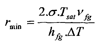
nucleation cavities 16 can be spaced by a distance S where the ratio of cavity spacing S to the bubble departure diameter Db is greater than or equal to about three (S/Db ≥3). Of course, cavity spacing slightly less than three may be sufficient to avoid interaction between nucleation sites in some cases. Bubble departure diameter Db can be predicted by the equation
where ρl is the liquid coolant density, ρν is the vapor coolant density, α is the thermal diffusivity, g is the gravitational constant, Cp is specific heat, ΔT is the superheat temperature Ts - Tsat, and λ is the latent heat of evaporization. For excess temperature or superheat ΔT in the range of about 1°C to about 10°C, bubble diameter of conventional coolant is predicted to be in the range of about 0.1 mm to about 1.4 mm. Thus, in an effort to avoid nucleation site interaction, spacing S betweennucleation cavities 16 can be selected to be in the range of about 0.3 mm to about 4.2 mm. - Although not necessarily the case, a larger cavity diameter d will typically be associated with smaller cavity spacing S and vice versa. This is generally true due to the interaction between bubble departure diameter, superheat, and desired cavity spacing. As mentioned above, bubble departure diameter Db determines the desired spacing of nucleation cavities if site interaction is to be avoided. Bubble departure diameter Db is a function, in part, of superheat ΔT. Thus, higher levels of superheat ΔT results in larger diameter bubbles and thus in a selection of larger spacing S between
nucleation cavities 16. At the same time, higher levels of superheat ΔT activates smaller diameter nucleation cavities. Thus, cavity diameter d and cavity spacing S can be selected based on the superheat temperature ΔT at which start of nucleate boiling is desired, where increasing the target superheat temperature ΔT associated with onset of nucleate boiling results in selecting a larger cavity spacing and a smaller cavity diameter d. - The depth of the
nucleation cavities 16 is selected to be at least sufficient that surface tension will not preclude coolant from entering the cavities. Preferably, however, the depth of the nucleation cavities is selected to be at least equal to the diameter d of thenucleation cavities 16, thus provide a depth-to-width ration of at least 1. Of course, the depth-to-width ratio can be greater than 1 without departing from the scope of this invention. - The nucleation cavities 16 may have a variety of shape, such as shapes that have parallel sidewalls and thus a uniform cross-sectional area along the depth of the cavity16 as shown in
FIG. 6 . The shape may also be a re-entrant shape as shown inFIG. 7 in which the sidewalls diverge from the opening at thesurface 12, thus providing an increasing cross-sectional shape long the depth. Similarly, the sidewalls may diverge from the bottom of thecavity 16 toward the opening at thesurface 12 as shown inFIG. 8 , thus providing a decreasing cross-sectional area along the depth of thecavity 16. The opening of thecavities 16 may have any suitable shape, such as a circular, oval, triangular, rectangular, any polygonal, or any free-form shape for example. - Referring back to
FIG. 1 , the use of a surface configuration as described above at selected locations within a coolant circuit effectively inhibits changes transitions from nucleate boiling to film boiling. In this regard, transitions from nucleate boiling to film boiling are not absolutely prevented, but they are avoided for practical ranges of heat flux. The solid line graph inFIG. 1 illustrates the heat transfer regimes of an ordinary, untreated surface in a coolant circuit, which may have any number of randomly spaced and randomly sized cavities formed therein. As a result, as heat flux increases and nucleate boiling becomes more vigorous, the coolant to reach departure from nucleate boiling at a critical heat flux q"=CHF0. In addition, during the nucleate boiling phase, the superheat gradient, d(Ts-Tsat)/dq", is relatively high. The superheat temperature ΔT at which nucleation and nucleate boiling occur can be pre-selected by selecting and appropriate cavity diameter d together with appropriate cavity spacing S as described above. In addition, by specially preparing theinsert surface 12 to remove random, small diameter cavities (e.g. by polishing), heat flux can be increased without activating additional nucleation sites. Use of a surface configuration as described above causes the critical heat flux associated with departure from nucleate boiling to be increased to q" = CHFI, as indicated by the dashed line curve inFIG. 1 . Moreover, the superheat gradient is decreased as indicated by the steeper dashed line during nucleate boiling. Thus, not only are higher heat flux levels required to reach the new departure from nucleate boiling at point DNB', but changes in heat flux result in smaller increases in excess temperature or superheat at the locations where the surface configuration is provided. -
FIGS. 9 through 11 show an exemplary use of a cooling arrangement in accordance with this invention.FIG. 9 is a top plan view of aconventional cylinder head 20 for an internal combustion engine (not shown), whichcylinder head 20 include various coolant passages that form part of a coolant circuit of the engine. With reference toFIG. 10 , which shown a portion of thecylinder head 20 without or prior to application of the cooling arrangement of this invention, thecylinder head 20 includes anintake port 22 and anexhaust port 24 that are respectively opened and closed by intake and exhaust valves (not shown). Each valve conventionally includes a valve body portion that opens or closes theport valve guide exhaust port 24. The combustion process and the discharge of exhaust gases cause the cylinder head surface temperatures to increase.Various coolant passages cylinder head 20 and form part of a coolant circuit. Coolant flows through the coolant passages30, 32, 34, 36 to cool the surfaces of thecylinder head 20, and the heated coolant is then delivered to a heat exchanger in a well-known manner.Coolant passage 30 extends through the valve bridge, which is the portion of thecylinder head 20 that is between theintake port 22 and theexhaust port 24. -
FIG. 11 shows thecylinder head 20 fitted with a cooling arrangement in accordance with this invention. In the illustrated embodiment, coolant circuit inserts 10A, 10B, 10C is provided in each of thecoolant passages - Of course, any number of
inserts 10 could be used at various locations within the coolant circuit. Theinsert 10A is provided in thecoolant passage 30 that extends through the valve bridge. Theinsert 10A is a tubular member as described above. Thetubular insert 10A can be mounted in position by "cool-shrink" process in which theinsert 10A is cooled to shrink its size and then inserted into a bore or hole that substantially matches the cooled size of theinsert 10A. Thus, at normal temperatures, theinsert 10A expands and is thus held within the bore. Theinsert 10A can alternatively be formed from plural arcuate insert sections. Theinsert 10B has acurved insert surface 12 as described above with regard toFIG. 3 . Theinsert 10C has a substantiallyplanar insert surface 12 as described above with regard toFIG. 2 . - The
inserts 10 can be secured to thecylinder head 20 in a variety of manners. Where the locations within thecooling passages inserts 10 can be held in position by suitable fastening means, such a "cool-shrink" fitting as mentioned above, press-fitting, welding, or use of adhesives. In many cases, however, the desirable locations forinserts 10 are locations that are not easily accessible after thecylinder head 20 has been cast. In those cases, theinserts 10 can be positioned in thecast cylinder head 20 during the casting process. Theinserts 10 would be positioned into the sand mold used to cast thecylinder head 20 so that, when molten metal is poured or injected into the mold, the inserts would adhere to theresultant cylinder head 20 is the selected locations. - Although the preferred embodiments of this invention have been described herein, improvements and modifications may be incorporated without departing from the scope of the following claims. For example, although this invention is described in detail in the context of a cooling arrangement for an internal combustion engine, this invention may also be applied to any application in which selected surface in a coolant circuit have a tendency to experience higher levels of heat flux compared to adjacent surface and/or are more susceptible to film boiling. This invention may also be useful with liquid circuits in which the liquid is not primarily a coolant, such as engine fuel circuits for example, if the liquid is susceptible to film boiling or other undesirable boiling states.
Claims (25)
- A cooling arrangement, comprising:a coolant circuit formed at least in part by a cast metal body and having a surface of the cast body to be cooled, said surface having a tendency to experience high heat flux in comparison to adjacent surfaces in the coolant circuit, said surface including an insert (10) provided on the cast metal body and having an insert surface (12) forming at least a portion of said coolant circuit surface; anda surface configuration (16) provided on at least a portion of said insert surface, said surface configuration tending to inhibit a change in boiling state.
- The cooling arrangement of claim 1 wherein coolant circuit surfaces adjacent to said insert surface (12) are devoid of said surface configuration.
- The cooling arrangement of any preceding claim, wherein said surface configuration (16) raises the critical heat flux associated with departure from nucleate boiling of coolant adjacent to said surface.
- The cooling arrangement of any preceding claim, wherein said surface configuration (16) decreases the superheat gradient of coolant adjacent to said surface.
- The cooling arrangement of any preceding claim, wherein said surface configuration comprises a matrix (14) of substantially uniform nucleation cavities (16).
- The cooling arrangement of claim 5, wherein said surface is otherwise substantially free of cavities.
- The cooling arrangement of any of claims 5 to 6, wherein said matrix (14) comprises an equilateral triangle matrix in which each nucleation cavity (16) is substantially equally spaced from adjacent nucleation cavities.
- The cooling arrangement of any of claims 5-7, wherein adjacent nucleation cavities (16) are spaced by a distance in the range of about 0.3 mm to about 4.2 mm.
- The cooling arrangement of any of claims 5-8 wherein the nucleation cavities (16) have a diameter in the range of about 10 µm to about 250 µm.
- The cooling arrangement of any of claims 5-9, wherein the ratio of the distance between adjacent nucleation cavities (16) to the diameter of bubbles departing the nucleation cavities is greater than 3.
- The cooling arrangement of any of claims 5-10 wherein adjacent nucleation cavities (16) are spaced apart by a distance sufficient to prevent bubble departure interaction between adjacent nucleation cavities.
- The cooling arrangement of any preceding claim, wherein said insert (10) includes non-ferrous metal.
- The cooling arrangement of any preceding claim, wherein said insert surface (12) comprises a substantially planar surface.
- The cooling arrangement of any preceding claim, wherein said insert surface (12) comprises a curved surface.
- The cooling arrangement of any preceding claim, wherein said insert (10A) comprises a tubular member.
- The cooling arrangement of claim 15 wherein said tubular member has a radially inwardly facing surface, and wherein said insert surface (12) comprises said radially inwardly facing surface.
- The cooling arrangement of any preceding claim, wherein said insert (10) is mounted to said cast body after the body is cast.
- The cooling arrangement of any preceding claim, wherein said insert (10) is fastened to said cast body during the casting of said body.
- A method for altering the boiling character of a surface in a coolant circuit formed at least in part by a cast metal body, comprising:identifying a surface in the coolant circuit having a tendency to experience high heat flux in comparison to adjacent surfaces in the coolant circuit;providing an insert (10) on the cast metal body, the insert having an insert surface (12) adapted to form at least a portion of said coolant circuit surface;providing a surface configuration (16) on at least a portion of said insert surface, said surface configuration tending to inhibit a change in boiling state; andpositioning said insert surface (12) at the surface in the coolant circuit having a tendency to experience high heat flux in comparison to adjacent surfaces in the coolant circuit.
- The method of claim 19 wherein said step of providing said surface configuration includes forming a matrix (14) of substantially uniform nucleation cavities (16) in said surface.
- The method of claim 20 wherein said step of providing said surface configuration includes processing the surface so that it is substantially free from cavities other than said substantially uniform nucleation cavities (16).
- The method of any of claims 19-21 further comprising:casting said cast metal a body that defines at least a portion of said coolant circuit; andsecuring said insert (10) to said cast body.
- The method of claim 22 further comprising:positioning said insert (10) against a surface of a mould adapted for casting said cast metal a body that defines at least a portion of said coolant circuit; andcasting said body so that said insert is secured in position in the coolant circuit defined by the cast body.
- An internal combustion engine, comprising:a cylinder head (20) having an intake port (22) and an exhaust port (24) being configured to direct gases from a combustion chamber, the cylinder head also including a valve bridge between the intake port and the exhaust port; anda cooling arrangement according to claim 1,wherein the coolant circuit of the cooling arrangement has at least one coolant passage (30, 34, 36) extending within the cylinder head, and
wherein the surface having a tendency to experience high heat flux is a surface of the coolant passage. - The internal combustion engine of claim 24, wherein the at least one coolant passage (30) extends through the valve bridge, and wherein at least a portion of the coolant passage surface extending through the valve bridge includes the surface configuration that tends to inhibit a change in the boiling state of the coolant.
Priority Applications (6)
| Application Number | Priority Date | Filing Date | Title |
|---|---|---|---|
| DE60230530T DE60230530D1 (en) | 2002-12-12 | 2002-12-12 | Cooling arrangement and method with selected and formed surfaces for preventing the change of boiling state |
| EP02258581A EP1428997B1 (en) | 2002-12-12 | 2002-12-12 | Cooling arrangement and method with selected surfaces configured to inhibit changes in boiling state |
| AT02258581T ATE418673T1 (en) | 2002-12-12 | 2002-12-12 | COOLING ARRANGEMENT AND METHOD WITH SELECTED AND DESIGNED SURFACES TO PREVENT CHANGE IN BOILING STATE |
| US10/732,217 US7028763B2 (en) | 2002-12-12 | 2003-12-11 | Cooling arrangement and method with selected surfaces configured to inhibit changes in boiling state |
| AU2003298438A AU2003298438A1 (en) | 2002-12-12 | 2003-12-11 | Cooling arrangement and method with selected surfaces configured to inhibit changes in boiling state |
| PCT/GB2003/005419 WO2004053308A1 (en) | 2002-12-12 | 2003-12-11 | Cooling arrangement and method with selected surfaces configured to inhibit changes in boiling state |
Applications Claiming Priority (1)
| Application Number | Priority Date | Filing Date | Title |
|---|---|---|---|
| EP02258581A EP1428997B1 (en) | 2002-12-12 | 2002-12-12 | Cooling arrangement and method with selected surfaces configured to inhibit changes in boiling state |
Publications (2)
| Publication Number | Publication Date |
|---|---|
| EP1428997A1 EP1428997A1 (en) | 2004-06-16 |
| EP1428997B1 true EP1428997B1 (en) | 2008-12-24 |
Family
ID=32319680
Family Applications (1)
| Application Number | Title | Priority Date | Filing Date |
|---|---|---|---|
| EP02258581A Expired - Lifetime EP1428997B1 (en) | 2002-12-12 | 2002-12-12 | Cooling arrangement and method with selected surfaces configured to inhibit changes in boiling state |
Country Status (6)
| Country | Link |
|---|---|
| US (1) | US7028763B2 (en) |
| EP (1) | EP1428997B1 (en) |
| AT (1) | ATE418673T1 (en) |
| AU (1) | AU2003298438A1 (en) |
| DE (1) | DE60230530D1 (en) |
| WO (1) | WO2004053308A1 (en) |
Families Citing this family (12)
| Publication number | Priority date | Publication date | Assignee | Title |
|---|---|---|---|---|
| US9275887B2 (en) | 2006-07-20 | 2016-03-01 | Applied Materials, Inc. | Substrate processing with rapid temperature gradient control |
| US7421983B1 (en) | 2007-03-26 | 2008-09-09 | Brunswick Corporation | Marine propulsion system having a cooling system that utilizes nucleate boiling |
| US20080295996A1 (en) * | 2007-05-31 | 2008-12-04 | Auburn University | Stable cavity-induced two-phase heat transfer in silicon microchannels |
| WO2009106143A1 (en) * | 2008-02-29 | 2009-09-03 | Perkins Engines Company Limited | Clustered nucleate boiling cavity grid |
| US8997846B2 (en) * | 2008-10-20 | 2015-04-07 | The Government Of The United States Of America, As Represented By The Secretary Of The Navy | Heat dissipation system with boundary layer disruption |
| FR2945337B1 (en) * | 2009-05-06 | 2012-05-25 | Commissariat Energie Atomique | THERMAL EXCHANGE DEVICE WITH INCREASED THERMAL EXCHANGE COEFFICIENT AND METHOD OF MAKING SAME |
| CN101929819A (en) * | 2009-06-26 | 2010-12-29 | 富准精密工业(深圳)有限公司 | Flat-plate heat pipe |
| US20110203772A1 (en) * | 2010-02-19 | 2011-08-25 | Battelle Memorial Institute | System and method for enhanced heat transfer using nanoporous textured surfaces |
| US10718575B2 (en) | 2017-12-21 | 2020-07-21 | Nokia Technolgies Oy | Apparatus for coalescence induced droplet jumping |
| US20230125822A1 (en) * | 2021-10-27 | 2023-04-27 | Intel Corporation | Immersion cooling for integrated circuit devices |
| US12490410B2 (en) | 2021-12-06 | 2025-12-02 | Intel Corporation | Circuit devices integrated with boiling enhancement for two-phase immersion cooling |
| US12382609B2 (en) * | 2022-04-21 | 2025-08-05 | Quanta Computer Inc. | Nucleation surface treatment for thermal cooling |
Family Cites Families (21)
| Publication number | Priority date | Publication date | Assignee | Title |
|---|---|---|---|---|
| US3313276A (en) * | 1964-10-12 | 1967-04-11 | Yanmar Diesel Engine Co | Method of cooling a rotary engine |
| FR1476550A (en) * | 1965-07-07 | 1967-04-14 | Thomson Houston Comp Francaise | Surface boiling heat exchangers improvements |
| DE2205015A1 (en) * | 1972-02-03 | 1973-08-09 | Daimler Benz Ag | ROTARY PISTON COMBUSTION MACHINE IN TROCHOID DESIGN |
| US3964445A (en) * | 1974-05-03 | 1976-06-22 | Ford Motor Company | Water cooling system - Wankel engine |
| US3990862A (en) * | 1975-01-31 | 1976-11-09 | The Gates Rubber Company | Liquid heat exchanger interface and method |
| US4050507A (en) * | 1975-06-27 | 1977-09-27 | International Business Machines Corporation | Method for customizing nucleate boiling heat transfer from electronic units immersed in dielectric coolant |
| US4037998A (en) * | 1975-11-03 | 1977-07-26 | Caterpillar Tractor Co. | Rotary engine cooling |
| US4136427A (en) * | 1977-02-16 | 1979-01-30 | Uop Inc. | Method for producing improved heat transfer surface |
| DE3162696D1 (en) * | 1980-12-02 | 1984-04-19 | Imi Marston Ltd | Heat exchanger |
| US4474231A (en) | 1981-08-05 | 1984-10-02 | General Electric Company | Means for increasing the critical heat flux of an immersed surface |
| JPS60229353A (en) * | 1984-04-27 | 1985-11-14 | Hitachi Ltd | Heat transfering device |
| JPS60243490A (en) * | 1984-05-17 | 1985-12-03 | Matsushita Electric Ind Co Ltd | Manufacture of heat-transmitting pipe for boiling |
| US4531900A (en) * | 1984-06-07 | 1985-07-30 | John Deere Technologies International, Inc. | Rotary engine cooling system |
| JPS6115088A (en) * | 1984-06-28 | 1986-01-23 | Matsushita Electric Ind Co Ltd | Boiling heat exchanger tube |
| DE3521790A1 (en) * | 1985-06-19 | 1987-01-02 | Kloeckner Humboldt Deutz Ag | INTERNAL COMBUSTION ENGINE WITH AT LEAST ONE LIQUID-COOLED CYLINDER |
| US4653572A (en) * | 1986-03-11 | 1987-03-31 | Air Products And Chemicals, Inc. | Dual-zone boiling process |
| US4768484A (en) * | 1987-07-13 | 1988-09-06 | General Motors Corporation | Actively pressurized engine cooling system |
| US6371199B1 (en) * | 1988-02-24 | 2002-04-16 | The Trustees Of The University Of Pennsylvania | Nucleate boiling surfaces for cooling and gas generation |
| US5031579A (en) * | 1990-01-12 | 1991-07-16 | Evans John W | Cooling system for internal combustion engines |
| US5444909A (en) * | 1993-12-29 | 1995-08-29 | Intel Corporation | Method of making a drop-in heat sink |
| US5544696A (en) * | 1994-07-01 | 1996-08-13 | The United States Of America As Represented By The Secretary Of The Air Force | Enhanced nucleate boiling heat transfer for electronic cooling and thermal energy transfer |
-
2002
- 2002-12-12 EP EP02258581A patent/EP1428997B1/en not_active Expired - Lifetime
- 2002-12-12 DE DE60230530T patent/DE60230530D1/en not_active Expired - Lifetime
- 2002-12-12 AT AT02258581T patent/ATE418673T1/en not_active IP Right Cessation
-
2003
- 2003-12-11 AU AU2003298438A patent/AU2003298438A1/en not_active Abandoned
- 2003-12-11 US US10/732,217 patent/US7028763B2/en not_active Expired - Fee Related
- 2003-12-11 WO PCT/GB2003/005419 patent/WO2004053308A1/en not_active Ceased
Also Published As
| Publication number | Publication date |
|---|---|
| EP1428997A1 (en) | 2004-06-16 |
| ATE418673T1 (en) | 2009-01-15 |
| AU2003298438A1 (en) | 2004-06-30 |
| US20040200442A1 (en) | 2004-10-14 |
| WO2004053308A1 (en) | 2004-06-24 |
| US7028763B2 (en) | 2006-04-18 |
| DE60230530D1 (en) | 2009-02-05 |
Similar Documents
| Publication | Publication Date | Title |
|---|---|---|
| US7028763B2 (en) | Cooling arrangement and method with selected surfaces configured to inhibit changes in boiling state | |
| EP1514999B1 (en) | Turbine blade platform cooling system | |
| US7198026B2 (en) | Divider plate for an inlet port, sand core for forming an inlet port, and cylinder head | |
| EP1813776A2 (en) | Microcircuits for cooling of small turbine engine blades | |
| US10286448B2 (en) | High-performance tool cooling system | |
| US6557621B1 (en) | Casting core and method of casting a gas turbine engine component | |
| US20090028703A1 (en) | Airfoil mini-core plugging devices | |
| JP2008144760A (en) | Turbine engine component, and method for forming airfoil portion of turbine engine component | |
| CN102667125A (en) | Pistons with a rough surface | |
| Saha et al. | Instability in flow boiling in microchannels | |
| US20090266436A1 (en) | Methods for stabilizing flow in channels and systems thereof | |
| EP2578836A2 (en) | Cooling unit for engine | |
| WO2003085250A1 (en) | Cylinder head | |
| KR20060048479A (en) | Turbine blades | |
| WO2007108961A2 (en) | Thermal chuck and processes for manufacturing the thermal chuck | |
| JP6991076B2 (en) | Devices and methods for cooling components that come into contact with molten glass | |
| FR2685229A1 (en) | Method for consumable- (disposable-) pattern moulding and refrigerating element for implementing this method | |
| Campbell et al. | Incorporating nucleate boiling in a precision cooling strategy for combustion engines | |
| US20080063533A1 (en) | Turbine blade for a gas turbine engine | |
| US20110203764A1 (en) | Combustion chamber wall cooling chamber design for semi-permanent mold cylinder head casting | |
| US6333069B1 (en) | Method for preventing harm from constrictions formed during coating with a protective coat in the cooling holes of gas-cooled parts | |
| EP2883977A1 (en) | Method for coating a component with holes | |
| US10507521B2 (en) | Mould for casting a monocrystalline component | |
| JP4276922B2 (en) | Casting equipment | |
| JPH03142058A (en) | Casting method |
Legal Events
| Date | Code | Title | Description |
|---|---|---|---|
| PUAI | Public reference made under article 153(3) epc to a published international application that has entered the european phase |
Free format text: ORIGINAL CODE: 0009012 |
|
| AK | Designated contracting states |
Kind code of ref document: A1 Designated state(s): AT BE BG CH CY CZ DE DK EE ES FI FR GB GR IE IT LI LU MC NL PT SE SI SK TR |
|
| AX | Request for extension of the european patent |
Extension state: AL LT LV MK RO |
|
| 17P | Request for examination filed |
Effective date: 20041201 |
|
| AKX | Designation fees paid |
Designated state(s): AT BE BG CH CY CZ DE DK EE ES FI FR GB GR IE IT LI LU MC NL PT SE SI SK TR |
|
| RAP1 | Party data changed (applicant data changed or rights of an application transferred) |
Owner name: PERKINS ENGINES COMPANY LIMITED |
|
| 17Q | First examination report despatched |
Effective date: 20070613 |
|
| GRAP | Despatch of communication of intention to grant a patent |
Free format text: ORIGINAL CODE: EPIDOSNIGR1 |
|
| GRAS | Grant fee paid |
Free format text: ORIGINAL CODE: EPIDOSNIGR3 |
|
| GRAA | (expected) grant |
Free format text: ORIGINAL CODE: 0009210 |
|
| AK | Designated contracting states |
Kind code of ref document: B1 Designated state(s): AT BE BG CH CY CZ DE DK EE ES FI FR GB GR IE IT LI LU MC NL PT SE SI SK TR |
|
| REG | Reference to a national code |
Ref country code: GB Ref legal event code: FG4D |
|
| REG | Reference to a national code |
Ref country code: CH Ref legal event code: EP |
|
| REG | Reference to a national code |
Ref country code: IE Ref legal event code: FG4D |
|
| REF | Corresponds to: |
Ref document number: 60230530 Country of ref document: DE Date of ref document: 20090205 Kind code of ref document: P |
|
| PG25 | Lapsed in a contracting state [announced via postgrant information from national office to epo] |
Ref country code: NL Free format text: LAPSE BECAUSE OF FAILURE TO SUBMIT A TRANSLATION OF THE DESCRIPTION OR TO PAY THE FEE WITHIN THE PRESCRIBED TIME-LIMIT Effective date: 20081224 Ref country code: FI Free format text: LAPSE BECAUSE OF FAILURE TO SUBMIT A TRANSLATION OF THE DESCRIPTION OR TO PAY THE FEE WITHIN THE PRESCRIBED TIME-LIMIT Effective date: 20081224 Ref country code: SI Free format text: LAPSE BECAUSE OF FAILURE TO SUBMIT A TRANSLATION OF THE DESCRIPTION OR TO PAY THE FEE WITHIN THE PRESCRIBED TIME-LIMIT Effective date: 20081224 |
|
| NLV1 | Nl: lapsed or annulled due to failure to fulfill the requirements of art. 29p and 29m of the patents act | ||
| PG25 | Lapsed in a contracting state [announced via postgrant information from national office to epo] |
Ref country code: EE Free format text: LAPSE BECAUSE OF FAILURE TO SUBMIT A TRANSLATION OF THE DESCRIPTION OR TO PAY THE FEE WITHIN THE PRESCRIBED TIME-LIMIT Effective date: 20081224 Ref country code: BE Free format text: LAPSE BECAUSE OF FAILURE TO SUBMIT A TRANSLATION OF THE DESCRIPTION OR TO PAY THE FEE WITHIN THE PRESCRIBED TIME-LIMIT Effective date: 20081224 Ref country code: BG Free format text: LAPSE BECAUSE OF FAILURE TO SUBMIT A TRANSLATION OF THE DESCRIPTION OR TO PAY THE FEE WITHIN THE PRESCRIBED TIME-LIMIT Effective date: 20090324 Ref country code: ES Free format text: LAPSE BECAUSE OF FAILURE TO SUBMIT A TRANSLATION OF THE DESCRIPTION OR TO PAY THE FEE WITHIN THE PRESCRIBED TIME-LIMIT Effective date: 20090404 |
|
| PG25 | Lapsed in a contracting state [announced via postgrant information from national office to epo] |
Ref country code: AT Free format text: LAPSE BECAUSE OF FAILURE TO SUBMIT A TRANSLATION OF THE DESCRIPTION OR TO PAY THE FEE WITHIN THE PRESCRIBED TIME-LIMIT Effective date: 20081224 Ref country code: CZ Free format text: LAPSE BECAUSE OF FAILURE TO SUBMIT A TRANSLATION OF THE DESCRIPTION OR TO PAY THE FEE WITHIN THE PRESCRIBED TIME-LIMIT Effective date: 20081224 Ref country code: PT Free format text: LAPSE BECAUSE OF FAILURE TO SUBMIT A TRANSLATION OF THE DESCRIPTION OR TO PAY THE FEE WITHIN THE PRESCRIBED TIME-LIMIT Effective date: 20090525 Ref country code: SE Free format text: LAPSE BECAUSE OF FAILURE TO SUBMIT A TRANSLATION OF THE DESCRIPTION OR TO PAY THE FEE WITHIN THE PRESCRIBED TIME-LIMIT Effective date: 20090324 |
|
| PG25 | Lapsed in a contracting state [announced via postgrant information from national office to epo] |
Ref country code: SK Free format text: LAPSE BECAUSE OF FAILURE TO SUBMIT A TRANSLATION OF THE DESCRIPTION OR TO PAY THE FEE WITHIN THE PRESCRIBED TIME-LIMIT Effective date: 20081224 |
|
| PG25 | Lapsed in a contracting state [announced via postgrant information from national office to epo] |
Ref country code: DK Free format text: LAPSE BECAUSE OF FAILURE TO SUBMIT A TRANSLATION OF THE DESCRIPTION OR TO PAY THE FEE WITHIN THE PRESCRIBED TIME-LIMIT Effective date: 20081224 |
|
| PLBE | No opposition filed within time limit |
Free format text: ORIGINAL CODE: 0009261 |
|
| STAA | Information on the status of an ep patent application or granted ep patent |
Free format text: STATUS: NO OPPOSITION FILED WITHIN TIME LIMIT |
|
| 26N | No opposition filed |
Effective date: 20090925 |
|
| PG25 | Lapsed in a contracting state [announced via postgrant information from national office to epo] |
Ref country code: MC Free format text: LAPSE BECAUSE OF NON-PAYMENT OF DUE FEES Effective date: 20100701 |
|
| REG | Reference to a national code |
Ref country code: CH Ref legal event code: PL |
|
| REG | Reference to a national code |
Ref country code: FR Ref legal event code: ST Effective date: 20100831 |
|
| REG | Reference to a national code |
Ref country code: IE Ref legal event code: MM4A |
|
| PG25 | Lapsed in a contracting state [announced via postgrant information from national office to epo] |
Ref country code: IE Free format text: LAPSE BECAUSE OF NON-PAYMENT OF DUE FEES Effective date: 20091212 Ref country code: LI Free format text: LAPSE BECAUSE OF NON-PAYMENT OF DUE FEES Effective date: 20091231 Ref country code: CH Free format text: LAPSE BECAUSE OF NON-PAYMENT OF DUE FEES Effective date: 20091231 Ref country code: FR Free format text: LAPSE BECAUSE OF NON-PAYMENT OF DUE FEES Effective date: 20091231 Ref country code: GR Free format text: LAPSE BECAUSE OF FAILURE TO SUBMIT A TRANSLATION OF THE DESCRIPTION OR TO PAY THE FEE WITHIN THE PRESCRIBED TIME-LIMIT Effective date: 20090325 |
|
| PG25 | Lapsed in a contracting state [announced via postgrant information from national office to epo] |
Ref country code: IT Free format text: LAPSE BECAUSE OF FAILURE TO SUBMIT A TRANSLATION OF THE DESCRIPTION OR TO PAY THE FEE WITHIN THE PRESCRIBED TIME-LIMIT Effective date: 20081224 |
|
| PG25 | Lapsed in a contracting state [announced via postgrant information from national office to epo] |
Ref country code: LU Free format text: LAPSE BECAUSE OF NON-PAYMENT OF DUE FEES Effective date: 20091212 |
|
| PG25 | Lapsed in a contracting state [announced via postgrant information from national office to epo] |
Ref country code: TR Free format text: LAPSE BECAUSE OF FAILURE TO SUBMIT A TRANSLATION OF THE DESCRIPTION OR TO PAY THE FEE WITHIN THE PRESCRIBED TIME-LIMIT Effective date: 20081224 |
|
| PG25 | Lapsed in a contracting state [announced via postgrant information from national office to epo] |
Ref country code: CY Free format text: LAPSE BECAUSE OF FAILURE TO SUBMIT A TRANSLATION OF THE DESCRIPTION OR TO PAY THE FEE WITHIN THE PRESCRIBED TIME-LIMIT Effective date: 20081224 |
|
| PGFP | Annual fee paid to national office [announced via postgrant information from national office to epo] |
Ref country code: GB Payment date: 20141124 Year of fee payment: 13 |
|
| PGFP | Annual fee paid to national office [announced via postgrant information from national office to epo] |
Ref country code: DE Payment date: 20141222 Year of fee payment: 13 |
|
| REG | Reference to a national code |
Ref country code: DE Ref legal event code: R119 Ref document number: 60230530 Country of ref document: DE |
|
| GBPC | Gb: european patent ceased through non-payment of renewal fee |
Effective date: 20151212 |
|
| PG25 | Lapsed in a contracting state [announced via postgrant information from national office to epo] |
Ref country code: GB Free format text: LAPSE BECAUSE OF NON-PAYMENT OF DUE FEES Effective date: 20151212 Ref country code: DE Free format text: LAPSE BECAUSE OF NON-PAYMENT OF DUE FEES Effective date: 20160701 |