EP1428721A2 - Combination switch apparatus - Google Patents
Combination switch apparatus Download PDFInfo
- Publication number
- EP1428721A2 EP1428721A2 EP03104221A EP03104221A EP1428721A2 EP 1428721 A2 EP1428721 A2 EP 1428721A2 EP 03104221 A EP03104221 A EP 03104221A EP 03104221 A EP03104221 A EP 03104221A EP 1428721 A2 EP1428721 A2 EP 1428721A2
- Authority
- EP
- European Patent Office
- Prior art keywords
- contact
- fixed contact
- combination switch
- switch apparatus
- fixed
- Prior art date
- Legal status (The legal status is an assumption and is not a legal conclusion. Google has not performed a legal analysis and makes no representation as to the accuracy of the status listed.)
- Withdrawn
Links
Images


Classifications
-
- B—PERFORMING OPERATIONS; TRANSPORTING
- B60—VEHICLES IN GENERAL
- B60Q—ARRANGEMENT OF SIGNALLING OR LIGHTING DEVICES, THE MOUNTING OR SUPPORTING THEREOF OR CIRCUITS THEREFOR, FOR VEHICLES IN GENERAL
- B60Q1/00—Arrangement of optical signalling or lighting devices, the mounting or supporting thereof or circuits therefor
- B60Q1/02—Arrangement of optical signalling or lighting devices, the mounting or supporting thereof or circuits therefor the devices being primarily intended to illuminate the way ahead or to illuminate other areas of way or environments
- B60Q1/04—Arrangement of optical signalling or lighting devices, the mounting or supporting thereof or circuits therefor the devices being primarily intended to illuminate the way ahead or to illuminate other areas of way or environments the devices being headlights
- B60Q1/14—Arrangement of optical signalling or lighting devices, the mounting or supporting thereof or circuits therefor the devices being primarily intended to illuminate the way ahead or to illuminate other areas of way or environments the devices being headlights having dimming means
- B60Q1/1446—Arrangement of optical signalling or lighting devices, the mounting or supporting thereof or circuits therefor the devices being primarily intended to illuminate the way ahead or to illuminate other areas of way or environments the devices being headlights having dimming means controlled by mechanically actuated switches
- B60Q1/1453—Hand actuated switches
- B60Q1/1461—Multifunction switches for dimming headlights and controlling additional devices, e.g. for controlling direction indicating lights
- B60Q1/1469—Multifunction switches for dimming headlights and controlling additional devices, e.g. for controlling direction indicating lights controlled by or attached to a single lever, e.g. steering column stalk switches
Definitions
- This invention relates to a combination switch apparatus which is mounted on a steering column of a vehicle, and can be inverted relative to a neutral position so as to effect a switching operation.
- Such a combination switch apparatus includes a first moving knob switch which can be angularlymoved in a roller-like manner to switch the operation of a front wiper between a stop position (OFF), an intermittent position (INT), a low speed position (LO) and a high speed position (HI). Also, this combination switch apparatus includes a second moving knob switch which can be angularlymoved in a roller-like manner to switch the operation of a rear wiper between a stop position (OFF) and an operative position (ON). This combination switch apparatus further includes a third moving knob switch which can be angularly moved in a roller-like manner to set a desired intermittent stop time of the front wiper between the shortest time and the longest time when the first moving knob switch is held in the intermittent position (INT).
- the combination switch apparatus further includes a washer switch, and the whole of the combination switch apparatus can be tilted relative to the steering column from a neutral position to a forward side (toward the driver) or a rearward side (toward the front side of the vehicle).
- the washer switch When the washer switch is tilted to the forward side, the washer switch activates a front washer, and when the washer switch is tilted to the rearward side, the washer switch activates a rear washer.
- the washer switch is of the self-returning type which returns to its neutral position when an operating force ceases to be applied thereto.
- a front wiper control circuit connected in parallel with a front washer control circuit, is activated, so that a jet of washing liquid is applied to a front windshield glass, and then the front wiper effects a first wiping operation. Then, when the washer switch ceases to be tilted to the forward side, the operation of the front washer is stopped, and the front wiper effects a last wiping operation, and then a front wiper blade returns to a predetermined stop position.
- a rear wiper control circuit connected in parallel with a rear washer control circuit, is activated, so that a jet of washing liquid is applied to a rear windshield glass, and then the rear wiper effects a first wiping operation. Then, when the washer switch ceases to be tilted to the rearward side, the operation of the rear washer is stopped, and the rear wiper effects a last wiping operation, and then a rear wiper blade returns to a predetermined stop position.
- Such a washer switch has the specific structure shown in Figs. 9 and 10.
- Fig. 9 shows a first switch 60 for the washers
- Fig. 10 shows a second switch 80 for the wipers.
- the first switch 60 comprises first and second fixed contacts 61 and 62, a common contact 63 provided between the first and second fixed contacts 61 and 62, a contact holder 64 which is common to this first switch and the second switch 70, a moving contact 65, and a casing 66 which is common to this first switch and the second switch 70.
- the first fixed contact 61 is connected to the front washer control circuit, and when the first fixed contact 61 is connected to the common contact 63 via the moving contact 65, the front washer control circuit is activated.
- the second fixed contact 62 is connected to the rear washer control circuit, and when the second fixed contact 62 is connected to the common contact 63 via the moving contact 65, the rear washer control circuit is activated.
- the common contact 63 is connected to a common power source or the common ground.
- the contact holder 64 holds the moving contact 65 through a spring 67, and when a knob 68, projecting from the casing 66, is pressed upon tilting of the combination switch apparatus apparatus, the contact holder 64 is slid in a left-right direction (in the drawings) within the casing 66.
- the center of the contact holder 64 is disposed at a position a1 (in the drawings), and the moving contact 65 is connected only to the common contact 63.
- the second switch 70 comprises third and fourth fixed contacts 71 and 72, common contacts 73 and 74, the contact holder 64, a moving contact 75, and the casing 66.
- the third fixed contact 71 is connected to the front wiper control circuit, andwhen the third fixed contact 71 is connected to the common contact 73 via the moving contact 75, the front wiper control circuit is activated.
- the fourth fixed contact 72 is connected to the rear wiper control circuit, and when the fourth fixed contact 72 is connected to the common contact 74 via the moving contact 75, the rear wiper control circuit is activated.
- the common contacts 73 and 74 are connected to the common power source or the common ground.
- the contact holder 64 holds the moving contact 75 through a spring 77, and when the knob 68, shown in Fig. 9, is pressed upon tilting of the combination switch apparatus apparatus, the contact holder 64 is slid in the left-right direction (in the drawings) within the casing 66.
- the center of the contact holder 64 is disposed at a position b1 (identical to the position a1 in the drawings), and the moving contact 75 is connected only to the common contacts 73 and 74.
- the first and second switches 60 and 70 effect their respective switching operations at the same time, and activate the front washer and the front wiper or the rear washer or the rear wiper at the same time, respectively.
- This invention has been made in order to solve the above problem, and an object of the invention is to provide a combination switch apparatus in which a special design is incorporated in the structure of the switch operable by manipulation, so that the combination switch apparatus is excellent from the viewpoint of the cost.
- the invention is characterized by having the following arrangement.
- Fig. 1 is a plan view of one preferred embodiment of the combination switch apparatus of the invention
- Fig. 2 is a partly-broken, bottom view of the combination switch apparatus of Fig. 1
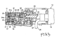
- Fig. 3 is a partly-broken, longitudinal cross-sectional view of the combination switch apparatus of Fig. 1
- Fig. 4 is a cross-sectional view showing an operative condition of a first switch when tilting the combination switch apparatus of Fig. 1 in a first direction
- Fig. 5 is a cross-sectional view showing an operative condition of the first switch when tilting the combination switch apparatus of Fig. 1 in a second direction.
- Fig. 1 is a plan view of one preferred embodiment of the combination switch apparatus of the invention
- Fig. 2 is a partly-broken, bottom view of the combination switch apparatus of Fig. 1
- Fig. 3 is a partly-broken, longitudinal cross-sectional view of the combination switch apparatus of Fig. 1
- Fig. 4 is a cross-sectional view showing an
- Fig. 6 is a cross-sectional view showing an operative condition of a second switch when tilting the combination switch apparatus of Fig. 1 in the first direction
- Fig. 7 is a cross-sectional view showing an operative condition of the second switch when tilting the combination switch apparatus of Fig. 1 in the second direction
- Fig. 8 is a plan view of a fixed contact plate used in the combination switch apparatus of Fig. 1.
- the combination switch apparatus 10 of this embodiment comprises a body portion 1, first and second fixed knobs 12 and 13, first, second and third moving knobs 14, 15 and 16, and first and second switches 17 and 18 (shown in Fig. 3) each of which is switched by tilting it in a direction a or a direction b (in the drawings) about a tilting center position 11a of the body portion 11.
- the body portion 11 is fixed to a side portion of a steering column (not shown), and therefore the combination switch apparatus 10 is provided to project laterally from the steering column.
- the first and second fixed knobs 12 and 13 are fixedly mounted on the body portion 11 against rotation.
- the first moving knob 14 can be angularly moved relative to the first fixed knob 12 to be switched between a stop position (OFF), an intermittent position (INT), a low speed position (LO) and a high speed position (HI), thereby controlling the operation of a front wiper.
- the second moving knob 15 can be angularly moved relative to the first fixed knob 12 to be switched between a stop position (OFF) and an operative position (ON), thereby controlling the operation of a rear wiper.
- the third moving knob 16 can be angularly moved relative to the second fixed knob 12 to set a desired intermittent stop time of the front wiper between the predetermined shortest time and the predetermined longest time.
- a circuit board 19 is fixed to a bottom surface of the body portion 11 by screws 20, and a fixed contact plate 21 is fixed to the bottom surface by screws 20.
- a wire harness 22 is electrically connected to the circuit board 19, and a wire harness 23 is electrically connected to the fixed contact board 21.
- a wire harness 24 is extended to each of the moving knobs 14, 15 and 16.
- the fixed contact plate 21 is used for the first and second switches 17 and 18.
- a shaft 25 and a knob support member 26 which support the knobs 12, 13, 14, 15 and 16 are provided within the body portion 11 along an axis thereof.
- a slider pressing member 30 is provided at the proximal ends of the shaft 25 and knob support member 26, and this slider pressing member 30 is urged toward the shaft 25 via a spring 28 and a plunger 29, and therefore is engaged with the shaft 25.
- the sliderpressingmember 30, whilepivotallymoved is slightly displaced in a forward-rearward direction of the body portion 11 to press a slider 31.
- the slider 31 is urged toward the slider pressing member 30 by a spring 32 and a plunger 33, and therefore is engaged with the slider pressing member 30.
- An engagement recess 31a is formed in a proximal end portion of the slider 31, and a projection 34a, formed on a contact holder 34 forming part of the first and second switches 17 and 18, is engaged in the engagement recess 31a.
- the slider pressing member 30 is displaced, the slider 31 causes the contact holder 34 to slide in the forward-rearward direction (in Fig. 3).
- the first and second switches 17 and 18 are arranged in two rows, and are juxtaposed in the direction of the length of the body portion 11.
- the fixed contact plate 21 and the contact holder 34 are common to the switches 17 and 18.
- the first switch 17 comprises first and second fixed contacts 35 and 36, a common contact 37 provided between the first and second fixed contacts 35 and 36, and a moving contact 38.
- the first fixed contact 35 is connected to a front washer control circuit, and when the first fixed contact 35 is connected to the common contact 37 via the moving contact 38, the front washer control circuit is activated.
- the second fixed contact 36 is connected to a rear washer control circuit, and when the second fixed contact 36 is connected to the common contact 37 via the moving contact 38, the rear washer control circuit is activated.
- the common contact 37 is connected to a common power source or the common ground.
- the contact holder 34 holds the moving contact 38 through a spring 39, and when the projection 34a, projecting through a notch 11c formed through a partition wall 11b of the body portion 11, is pressed by the slider 31, the contact holder 34 is slid in a left-right direction in Fig. 4.
- the center of the contact holder 34 is disposed at a position A1 (in Fig. 4), and the moving contact 38 is connected only to the common contact 37.
- the contact holder 34 is slid from the neutral position A1 to a position A2 by tilting the combination switch apparatus 10 toward the forward side (that is, in the direction b in Fig. 1), the moving contact 38 is connected to the first fixed contact 35 and the common contact 37, so that the front washer control circuit is activated.
- the second switch 18 comprises third and fourth fixed contacts 40 and 41, common contacts 42 and 43 provided between the third and fourth fixed contacts 40 and 41, and a moving contact 44.
- the third fixed contact 40 is connected to a front wiper control circuit, and when the third fixed contact 40 is connected to the common contact 42 via the moving contact 44, the front wiper control circuit is activated.
- the fourth fixed contact 41 is connected to a rear wiper control circuit, and when the fourth fixed contact 41 is connected to the common contact 43 via the moving contact 44, the rear wiper control circuit is activated.
- the common contacts 42 and 43 are connected to the common power source or the common ground.
- the moving contact 44 is held by the contact holder 34 through a spring 45, and when the projection 34a of the contact holder 34 is pressed by the slider 31, the contact holder 64 is slid in the left-right direction (in the drawings).
- the center of the contact holder 34 is disposed at a position B1 (in Fig. 6) , and the moving contact 44 is connected only to the common contacts 42 and 43.
- the moving contact 44 is not connected to the third fixed contact 40. Then, when the contact holder 34 is slidingly moved slightly past the position B2 to reach a position B2', the moving contact 44 is connected to the third fixed contact 40 and the common contact 42, so that the front wiper control circuit is activated. Namely, the activation of the front wiper control circuit by the second switch 18 is effected in delayed relation to the activation of the front washer control circuit by the first switch 17.
- the moving contact 44 is not connected to the fourth fixed contact 41. Then, when the contact holder 34 is slidingly moved slightly past the position B3 to reach a position B3', the moving contact 44 is connected to the fourth fixed contact 41 and the common contact 43, so that the rear wiper control circuit is activated. Namely, the activation of the rear wiper control circuit by the second switch 18 is effected in delayed relation to the activation of the rear washer control circuit by the first switch 17.
- a contact pitch (distance) p2 between a center position C1 (corresponding to the neutral position A1, B1 of the contact holder 34) and the center of the third fixed contact 40 is larger than a contact pitch (distance) p1 between the center position C1 and the center of the first fixed contact 35 as shown in Fig. 8.
- a contact pitch p2 between the center position C1 and the center of the fourth fixed contact 41 is larger than a contact pitch p1 between the center position C1 and the center of the second fixed contact 36.
- the contact pitch of the second switch 18 is larger than the contact pitch of the first switch 17.
- the moving contact 38 of the first switch 17 is connected to the first fixed contact 35 and the common contact 37, thereby activating the front washer control circuit.
- the moving contact 44 is connected to the third fixed contact 40 and the common contact 42 in slightly-delayed relation to the first switch 17, so that the front wiper control circuit is activated.
- the activation of the front wiper control circuit by the second switch 18 is effected in delayed relation to the activation of the front washer control circuit by the first switch 17.
- the moving contact 38 of the first switch 17 is connected to the second fixed contact 36 and the common contact 37, thereby activating the rear washer control circuit.
- the moving contact 44 is connected to the fourth fixed contact 41 and the common contact 43 in slightly-delayed relation to the first switch 17, so that the rear wiper control circuit is activated.
- the activation of the rear wiper control circuit by the second switch 18 is effected in delayed relation to the activation of the rear washer control circuit by the first switch 17.
- At least a delay time is set between the closing of the first fixed contact 35 and the closing of the third fixed contact 40 upon tilting of the combination switch apparatus toward the forward side, or a delay time is set between the closing of the second fixed contact 36 and the closing of the fourth fixed contact 41 upon tilting of the combination switch apparatus toward the rearward side. Therefore, the first and third fixed contacts 35 and 40 or the second and fourth fixed contacts 36 and 41 will not be closed at the same time, but will be closed with a time delay inserted therebetween.
- the contact pitch of connection between the first fixed contact 35 and the common contact 37 is different from the contact pitch of connection between the third fixed contact 40 and the common contact 42.
- the contact pitch of connection between the second fixed contact 36 and the common contact 37 is different from the contact pitch of connection between the fourth fixed contact 41 and the common contact 43. Therefore, because of these different contact pitches, the first and third fixed contacts 35 and 40 or the second and fourth fixed contacts 36 and 41 will not be connected at the same time.
- the order of switchingof the two switches is made stable by the connections having the time difference, and therefore there is eliminated an arc discharge as produced when the two contacts are connected at the same time, and expensive sliding-purpose grease for dealing with the generation of an arc discharge does not need to be coated onto the contacts, and this is advantageous from the viewpoint of the cost.
- the delay time is provided between the closing of the first fixed contact 35 via the moving contact 38 and the closing of the third fixed contact 40 via the moving contact 44, or the delay time is provided between the closing of the second fixed contact 36 via the moving contact 38 and the closing of the fourth fixed contact 41 via the moving contact 44.
- the first and third fixed contacts 35 and 40 or the second and fourth fixed contacts 36 and 41 will not be closed at the same time via the moving contacts 38 and 44, but will be closed with the time delay inserted therebetween. Therefore, the order of switching of the two switches is made stable by this time difference, and therefore there is eliminated an arc discharge as produced when the two contacts are closed at the same time, and expensive sliding-purpose grease for dealing with the generation of an arc discharge does not need to be coated onto the contacts, and this is advantageous from the viewpoint of the cost.
- the combination switch apparatus of the invention is not limited to the above embodiment, and suitable changes and modifications can be made.
- the two common contacts, used in the second switch may be formed into an integral single contact.
- the moving contacts are not limited to the illustrated contacts, and a bar-like contact can be used as the moving contact, and a plate-like contact plate may be used as the fixed contact.
- the delay time is set between the closing of the first fixed contact and the closing of the third fixed contact upon tilting of the combination switch apparatus in the first direction, or the delay time is set between the closing of the second fixed contact and the closing of the fourth fixed contact upon tilting of the combination switch apparatus in the second direction. Therefore, the first and third fixed contacts or the second and fourth fixed contacts will not be closed at the same time, but will be closed with a time delay inserted therebetween.
- the contact pitch of connection between the first fixed contact and the common contact is different from the contact pitch of connection between the third fixed contact and the second common contact, or the contactpitch of connectionbetween the second fixed contact and the first common contact is different from the contact pitch of connection between the fourth fixed contact and the second common contact. Therefore, because of these different contact pitches, the first and third fixed contacts or the second and fourth fixed contacts will not be connected at the same time. Therefore, the order of switching of the two switches is made stable by the connections having the time difference, and therefore there is eliminated an arc discharge as produced when the two contacts are connected at the same time, and expensive sliding-purpose grease for dealing with the generation of an arc discharge does not need to be coated onto the contacts, and this is advantageous from the viewpoint of the cost.
- the delay time is provided between the closing of the first fixed contact via the moving contact and the closing of the third fixed contact via the moving contact, or the delay time is provided between the closing of the second fixed contact via the moving contact and the closing of the fourth fixed contact via the moving contact. Therefore, the first and third fixed contacts or the second and fourth fixed contacts will not be closed at the same time via the moving contacts, but will be closed with the time delay inserted therebetween.
Landscapes
- Engineering & Computer Science (AREA)
- Mechanical Engineering (AREA)
- Switches With Compound Operations (AREA)
- Rotary Switch, Piano Key Switch, And Lever Switch (AREA)
- Tumbler Switches (AREA)
Abstract
Description
Also, this combination switch apparatus includes a second moving knob switch which can be angularlymoved in a roller-like manner to switch the operation of a rear wiper between a stop position (OFF) and an operative position (ON).
This combination switch apparatus further includes a third moving knob switch which can be angularly moved in a roller-like manner to set a desired intermittent stop time of the front wiper between the shortest time and the longest time when the first moving knob switch is held in the intermittent position (INT).
The combination switch apparatus further includes a washer switch, and the whole of the combination switch apparatus can be tilted relative to the steering column from a neutral position to a forward side (toward the driver) or a rearward side (toward the front side of the vehicle). When the washer switch is tilted to the forward side, the washer switch activates a front washer, and when the washer switch is tilted to the rearward side, the washer switch activates a rear washer. The washer switch is of the self-returning type which returns to its neutral position when an operating force ceases to be applied thereto.
Then, when the washer switch ceases to be tilted to the forward side, the operation of the front washer is stopped, and the front wiper effects a last wiping operation, and then a front wiper blade returns to a predetermined stop position.
Then, when the washer switch ceases to be tilted to the rearward side, the operation of the rear washer is stopped, and the rear wiper effects a last wiping operation, and then a rear wiper blade returns to a predetermined stop position.
The second fixed
The
The
The fourth fixed
The
The
the closing of the first fixed contact is established by an electrical connection between the first fixed contact and a first common contact,
the closing of the second fixed contact is established by an electrical connection between the first fixed contact and the first common contact,
the closing of the third fixed contact is established by an electrical connection between the third fixed contact and a second common contact, and
the closing of the fourth fixed contact is established by an electrical contact between the fourth fixed contact and the second common contact.
a contact pitch between the first fixed contact and the first common contact is different from a contact pitch between the third fixed contact and the second common contact, and
a contact pitch between the second fixed contact and the first common contact is different from a contact pitch between the fourth fixed contact and the second common contact.
Fig. 6 is a cross-sectional view showing an operative condition of a second switch when tilting the combination switch apparatus of Fig. 1 in the first direction, Fig. 7 is a cross-sectional view showing an operative condition of the second switch when tilting the combination switch apparatus of Fig. 1 in the second direction, and Fig. 8 is a plan view of a fixed contact plate used in the combination switch apparatus of Fig. 1.
The
The second moving
The third moving
A
The first fixed
The
In the
The third
The fourth fixed
In the
Then, when the
Then, when the
Also, a contact pitch p2 between the center position C1 and the center of the fourth fixed
Then, in the second switch 1.8, the moving
Then, in the
Therefore, the first and third
Therefore, because of these different contact pitches, the first and third
The moving contacts are not limited to the illustrated contacts, and a bar-like contact can be used as the moving contact, and a plate-like contact plate may be used as the fixed contact.
Therefore, the first and third fixed contacts or the second and fourth fixed contacts will not be closed at the same time, but will be closed with a time delay inserted therebetween. Therefore, the order of switching of the two switches is made stable bythi s time di fference, andtherefore there is eliminated an arc discharge as produced when the two contacts are closed at the same time, and expensive sliding-purpose grease for dealing with the generation of an arc discharge does not need to be coated onto the contacts, and this is advantageous from the viewpoint of the cost.
Therefore, because of these different contact pitches, the first and third fixed contacts or the second and fourth fixed contacts will not be connected at the same time. Therefore, the order of switching of the two switches is made stable by the connections having the time difference, and therefore there is eliminated an arc discharge as produced when the two contacts are connected at the same time, and expensive sliding-purpose grease for dealing with the generation of an arc discharge does not need to be coated onto the contacts, and this is advantageous from the viewpoint of the cost.
Therefore, the first and third fixed contacts or the second and fourth fixed contacts will not be closed at the same time via the moving contacts, but will be closed with the time delay inserted therebetween. Therefore, the order of switching of the two switches is made stable by this time difference, and therefore there is eliminated an arc discharge as produced when the two contacts are closed at the same time, and expensive sliding-purpose grease for dealing with the generation of an arc discharge does not need to be coated onto the contacts, and this is advantageous from the viewpoint of the cost.
Claims (4)
- A combination switch apparatus adapted to be switched by tilting the combination switch apparatus in a first direction and a second direction with respect to a steering column, the combination switch apparatus comprising:wherein a delay time is set between the closing of the fixed contact of the first switch and the closing of the fixed contact of the second switch upon tilting of the combination switch in one of the first and second direction.a first switch including a first fixed contact which is closed upon tilting of the combination switch apparatus in the first direction and a second fixed contact which is closed upon tilting of the combination switch apparatus in the second direction; anda second switch including a third fixed contact which is closed upon tilting of the combination switch apparatus in the first direction and a second fixed contact which is closed upon tilting of the combination switch apparatus in the second direction,
- The combination switch according to claim 1, wherein
the closing of the first fixed contact is established by an electrical connection between the first fixed contact and a first common contact,
the closing of the second fixed contact is established by an electrical connection between the first fixed contact and the first common contact,
the closing of the third fixed contact is established by an electrical connection between the third fixed contact and a second common contact, and
the closing of the fourth fixed contact is established by an electrical contact between the fourth fixed contact and the second common contact. - The combination switch apparatus according to claim 2, wherein
a contact pitch between the first fixed contact and the first common contact is different from a contact pitch between the third fixed contact and the second common contact, and
a contact pitch between the second fixed contact and the first common contact is different from a contact pitch between the fourth fixed contact and the second common contact. - The combination switch apparatus according to any one of claims 1 through 3, wherein the first and second switches include a common contact holder which can be slid upon tilting of the combination switch apparatus, and a moving contact for the first switch and a moving contact for the second switch are held by the contact holder.
Applications Claiming Priority (2)
| Application Number | Priority Date | Filing Date | Title |
|---|---|---|---|
| JP2002332677 | 2002-11-15 | ||
| JP2002332677A JP2004171790A (en) | 2002-11-15 | 2002-11-15 | Combination switch |
Publications (2)
| Publication Number | Publication Date |
|---|---|
| EP1428721A2 true EP1428721A2 (en) | 2004-06-16 |
| EP1428721A3 EP1428721A3 (en) | 2005-08-17 |
Family
ID=32321668
Family Applications (1)
| Application Number | Title | Priority Date | Filing Date |
|---|---|---|---|
| EP03104221A Withdrawn EP1428721A3 (en) | 2002-11-15 | 2003-11-17 | Combination switch apparatus |
Country Status (2)
| Country | Link |
|---|---|
| EP (1) | EP1428721A3 (en) |
| JP (1) | JP2004171790A (en) |
Cited By (1)
| Publication number | Priority date | Publication date | Assignee | Title |
|---|---|---|---|---|
| CN102822926A (en) * | 2010-03-31 | 2012-12-12 | 耐力株式会社 | lever switch device |
Families Citing this family (2)
| Publication number | Priority date | Publication date | Assignee | Title |
|---|---|---|---|---|
| DE102005038145A1 (en) * | 2005-08-12 | 2007-02-15 | Leopold Kostal Gmbh & Co. Kg | steering column module |
| JP4713446B2 (en) * | 2006-11-24 | 2011-06-29 | 株式会社東海理化電機製作所 | Lever switch device for vehicle |
Family Cites Families (3)
| Publication number | Priority date | Publication date | Assignee | Title |
|---|---|---|---|---|
| DE2307855C3 (en) * | 1973-02-17 | 1978-10-05 | Swf-Spezialfabrik Fuer Autozubehoer Gustav Rau Gmbh, 7120 Bietigheim-Bissingen | Steering column switches for automobiles |
| DE3004034C2 (en) * | 1980-02-05 | 1983-03-17 | Leopold Kostal GmbH & Co KG, 5880 Lüdenscheid | Safety parking light switch in a combined direction indicator, parking light and steering column switch for motor vehicles |
| DE3108008C2 (en) * | 1980-02-05 | 1983-09-01 | Leopold Kostal GmbH & Co KG, 5880 Lüdenscheid | Safety parking light switch in a combined direction indicator, parking light and steering column switch for motor vehicles |
-
2002
- 2002-11-15 JP JP2002332677A patent/JP2004171790A/en not_active Abandoned
-
2003
- 2003-11-17 EP EP03104221A patent/EP1428721A3/en not_active Withdrawn
Cited By (3)
| Publication number | Priority date | Publication date | Assignee | Title |
|---|---|---|---|---|
| CN102822926A (en) * | 2010-03-31 | 2012-12-12 | 耐力株式会社 | lever switch device |
| CN102822926B (en) * | 2010-03-31 | 2015-06-17 | 耐力株式会社 | Lever switch device |
| US9233640B2 (en) | 2010-03-31 | 2016-01-12 | Niles Co., Ltd. | Lever switch device |
Also Published As
| Publication number | Publication date |
|---|---|
| EP1428721A3 (en) | 2005-08-17 |
| JP2004171790A (en) | 2004-06-17 |
Similar Documents
| Publication | Publication Date | Title |
|---|---|---|
| US5023530A (en) | Windshield wiper motor | |
| US6576855B2 (en) | Rocker switch | |
| EP0458292B1 (en) | Multifunction steering column switch | |
| US3879592A (en) | Switch having pivoted u-shaped resilient conductive blade | |
| US6399905B1 (en) | Lever switch and complex switch using the same | |
| EP1428721A2 (en) | Combination switch apparatus | |
| US4204099A (en) | Electrical switch | |
| US5182423A (en) | Electric switch for operating a windshield wiper and washer system of a motor vehicle | |
| KR101542858B1 (en) | Multi-function switch assembly of the vehicle | |
| US5760355A (en) | Electric switch for operating a windshield wiper and washer apparatus of a motor vehicle | |
| US5804782A (en) | Electrical switch having a rotary mechanism for use in an automotive vehicle | |
| US4427850A (en) | Monostable switch device for controlling the rear window washer/wiper of an automobile | |
| CN213988705U (en) | Handle mechanism for automobile combined switch | |
| EP1678731B1 (en) | Plunger contact assembly for an automobile control stalk | |
| GB2139815A (en) | Lever operated switches | |
| KR100704649B1 (en) | Contacting structure for wiper switch | |
| KR20080076144A (en) | Wiper switch | |
| US5817995A (en) | Wipe/wash switch | |
| KR200434677Y1 (en) | Moving terminal structure of car slide switch | |
| US3612785A (en) | Electrical switches with actuating and locating parts movable independently or concurrently | |
| CN215342329U (en) | An electric vehicle lamp control device | |
| JP2004206926A (en) | Switchgear | |
| US7411141B2 (en) | Combination switch | |
| KR100260217B1 (en) | Washer motor driving control system | |
| KR200148488Y1 (en) | Switch apparatus |
Legal Events
| Date | Code | Title | Description |
|---|---|---|---|
| PUAI | Public reference made under article 153(3) epc to a published international application that has entered the european phase |
Free format text: ORIGINAL CODE: 0009012 |
|
| AK | Designated contracting states |
Kind code of ref document: A2 Designated state(s): AT BE BG CH CY CZ DE DK EE ES FI FR GB GR HU IE IT LI LU MC NL PT RO SE SI SK TR |
|
| AX | Request for extension of the european patent |
Extension state: AL LT LV MK |
|
| PUAL | Search report despatched |
Free format text: ORIGINAL CODE: 0009013 |
|
| AK | Designated contracting states |
Kind code of ref document: A3 Designated state(s): AT BE BG CH CY CZ DE DK EE ES FI FR GB GR HU IE IT LI LU MC NL PT RO SE SI SK TR |
|
| AX | Request for extension of the european patent |
Extension state: AL LT LV MK |
|
| 17P | Request for examination filed |
Effective date: 20060124 |
|
| AKX | Designation fees paid |
Designated state(s): DE FR GB |
|
| STAA | Information on the status of an ep patent application or granted ep patent |
Free format text: STATUS: THE APPLICATION IS DEEMED TO BE WITHDRAWN |
|
| 18D | Application deemed to be withdrawn |
Effective date: 20061005 |