EP1428718A2 - Recliner adjuster - Google Patents
Recliner adjuster Download PDFInfo
- Publication number
- EP1428718A2 EP1428718A2 EP03028767A EP03028767A EP1428718A2 EP 1428718 A2 EP1428718 A2 EP 1428718A2 EP 03028767 A EP03028767 A EP 03028767A EP 03028767 A EP03028767 A EP 03028767A EP 1428718 A2 EP1428718 A2 EP 1428718A2
- Authority
- EP
- European Patent Office
- Prior art keywords
- gear
- seat back
- worm gear
- seat cushion
- seat
- Prior art date
- Legal status (The legal status is an assumption and is not a legal conclusion. Google has not performed a legal analysis and makes no representation as to the accuracy of the status listed.)
- Withdrawn
Links
Images



Classifications
-
- B—PERFORMING OPERATIONS; TRANSPORTING
- B60—VEHICLES IN GENERAL
- B60N—SEATS SPECIALLY ADAPTED FOR VEHICLES; VEHICLE PASSENGER ACCOMMODATION NOT OTHERWISE PROVIDED FOR
- B60N2/00—Seats specially adapted for vehicles; Arrangement or mounting of seats in vehicles
- B60N2/24—Seats specially adapted for vehicles; Arrangement or mounting of seats in vehicles for particular purposes or particular vehicles
- B60N2/42—Seats specially adapted for vehicles; Arrangement or mounting of seats in vehicles for particular purposes or particular vehicles the seat constructed to protect the occupant from the effect of abnormal g-forces, e.g. crash or safety seats
- B60N2/433—Safety locks for back-rests, e.g. with locking bars activated by inertia
-
- B—PERFORMING OPERATIONS; TRANSPORTING
- B60—VEHICLES IN GENERAL
- B60N—SEATS SPECIALLY ADAPTED FOR VEHICLES; VEHICLE PASSENGER ACCOMMODATION NOT OTHERWISE PROVIDED FOR
- B60N2/00—Seats specially adapted for vehicles; Arrangement or mounting of seats in vehicles
- B60N2/02—Seats specially adapted for vehicles; Arrangement or mounting of seats in vehicles the seat or part thereof being movable, e.g. adjustable
- B60N2/22—Seats specially adapted for vehicles; Arrangement or mounting of seats in vehicles the seat or part thereof being movable, e.g. adjustable the back-rest being adjustable
- B60N2/2231—Worm and worm gear articulations
-
- B—PERFORMING OPERATIONS; TRANSPORTING
- B60—VEHICLES IN GENERAL
- B60N—SEATS SPECIALLY ADAPTED FOR VEHICLES; VEHICLE PASSENGER ACCOMMODATION NOT OTHERWISE PROVIDED FOR
- B60N2/00—Seats specially adapted for vehicles; Arrangement or mounting of seats in vehicles
- B60N2/02—Seats specially adapted for vehicles; Arrangement or mounting of seats in vehicles the seat or part thereof being movable, e.g. adjustable
- B60N2/22—Seats specially adapted for vehicles; Arrangement or mounting of seats in vehicles the seat or part thereof being movable, e.g. adjustable the back-rest being adjustable
- B60N2/235—Seats specially adapted for vehicles; Arrangement or mounting of seats in vehicles the seat or part thereof being movable, e.g. adjustable the back-rest being adjustable by gear-pawl type mechanisms
Definitions
- the present invention relates to a recliner adjuster attached to, for example, an automobile seat for appropriately adjusting the inclination of a seat back with respect to a seat cushion.
- a sector gear is fixed to a seat back while a worm gear, which can be freely engaged with and disengaged from the sector gear, is rotatably attached to a seat cushion.
- the worm gear is connected to an operation shaft and, by pulling the operation shaft in the axial direction thereof and by subsequently lifting it up, the engagement between the worm gear and sector gear is released.
- the seat back tilts and the inclination thereof can be altered quickly.
- the worm gear and sector gear reengage to hold the seat back in that position.
- a sector gear and a worm gear having a lead angle greater than the friction angle are attached to a seat back and a seat cushion, respectively.
- the worm gear is caused to rotate by way of the sector gear, making it possible to appropriately alter the inclination of the seat back.
- Japanese Laid-Open Patent Publication (unexamined) No. 2000-342371 has proposed reducing the backlash between the sector gear and worm gear.
- the present invention has been developed to overcome the above-described disadvantages.
- the recliner adjuster includes a worm gear rotatably mounted on the seat cushion, a helical gear held in engagement with the worm gear, and an auxiliary locking mechanism by way of which the helical gear is mounted on the seat back.
- the seat back is held at a predetermined angle with respect to the seat cushion by the engagement of the helical gear with the worm gear.
- the auxiliary locking mechanism acts to hold the seat back at the predetermined angle with respect to the seat cushion.
- a compact recliner adjuster capable of withstanding a large load can be realized using a worm gear and a helical gear having a strength required in normal use.
- the auxiliary locking mechanism includes first and second gears having respective teeth surfaces spaced a predetermined distance, wherein the load greater than the predetermined value is inputted to the seat back, the first gear is partly deformed to engage with the second gear.
- the first gear is an external gear connected to the helical gear
- the second gear is an internal gear mounted on the seat cushion and disposed radially outward of the external gear
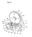
- Figs. 1 to 7 depict a recliner adjuster A according to the present invention, which includes a pair of brackets 2, 4 spaced a predetermined distance, a worm gear 6 rotatably mounted on the pair of brackets 2, 4, and a helical gear 8 held in engagement with the worm gear 6.
- the brackets 2, 4 are mounted on a seat cushion (not shown), while the helical gear 8 is mounted on a seat back (not shown) via a plurality of pins, an external gear, and a central shaft in the manner as explained later.
- the seat back is always biased frontward by an elastic force of a balance spring (not shown). Both the worm gear 6 and the helical gear 8 held in engagement with each other have a lead angle greater than the friction angle.
- the worm gear 6 has a front end rotatably supported by a front bearing 10 and a rear end rotatably supported by a rear bearing 12, and both the front and rear bearings 10, 12 are secured to the brackets 2, 4.
- the brackets 2, 4 have generally rectangular openings 2a, 4a defined therein at locations confronting the worm gear 6.
- the worm gear 6 partly protrudes externally through the openings 2a, 4a, thereby avoiding interference with the brackets 2, 4. That is, the presence of the openings 2a, 4a in the brackets 2, 4 can reduce the distance between the brackets 2, 4.
- the worm gear 6 has a large number of notches 6a in the form of a gear on a tooth crest thereof positioned in the proximity of the front bearing 10.
- a locking member 14 is interposed between the brackets 2, 4 so as to rotate about a mounting shaft 16 secured to the brackets 2, 4.
- the locking member 14 has a locking piece 14a that confronts the notches 6a from below for engagement with the notches 6a.
- the locking member 14 also has an operating lever 14b with which the locking piece 14a can be manually moved up and down to lock or unlock the notches 6a.
- the locking member 14 further has a lever 14c fixedly connected to one end of a coil spring (not shown), the other end of which is fixedly connected to a pin 18 secured to the brackets 2, 4.
- the operating lever 14b is connected to an operating knob (not shown) via a pin 17, which is loosely inserted in an elongated opening 4b defined in the bracket 4.
- the helical gear 8 has a round central hole 8a defined therein and is rotatably mounted on a central shaft 20 loosely inserted in the central hole 8a. As shown in Figs. 3 and 7, the central shaft 20 has a generally rectangular end that protrudes externally from the bracket 2 and is fixed to the seat back.
- the helical gear 8 also has a plurality of (for example, four) pin holes 8b defined therein around the central hole 8a at regular intervals, and one end of a pin 22 is received in each of the pin holes 8b.
- An external gear 26 fixed to the central shaft 20 is interposed between the helical gear 8 and the bracket 2 and brought into engagement with an internal gear 24 when a large load is inputted.
- the external gear 26 has a plurality of (for example, four) undulated slots 26a defined therein around the central shaft 20 at regular intervals, and the other end of the aforementioned pin 22 is loosely inserted in a central portion of each of the undulated slots 26a.
- the internal gear 24 is secured to the bracket 2 and concentrically disposed around the external gear 26 so that internal teeth of the former confront external teeth of the latter with a predetermined distance therebetween.
- the internal gear 24 has a cut-out defined at a lower portion thereof above the worm gear 6 to avoid interference with the worm gear 6.
- reference numerals 28, 30, 32, 34, 36 denote fixing shafts for holding the two brackets 2, 4 in a mutually spaced relationship.
- the recliner adjuster A of the above-described construction operates as follows.
- the locking member 14 Under the normal condition in which the operating knob connected to the pin 17 of the locking member 14 is not operated, the locking member 14 is biased in the direction of an arrow A by the elastic force of the coil spring fixedly connected to the lever 14c, and the locking piece 14a is held in engagement with one of the notches 6a of the worm gear 6. Accordingly, rotation of the worm gear 6 is not allowed, preventing rotation of the helical gear 8 held in engagement with the worm gear 6. Because the external gear 26 is fixed to the seat back via the central shaft 20 and connected to the helical gear 8 via the pins 22, the inclination of the seat back relative to the seat cushion is held at a predetermined angle.
- the operating knob is operated to rotate the locking member 14 in the direction counter to the direction of the arrow A against the elastic force of the coil spring.
- the engagement of the locking piece 14a with one of the notches 6a of the worm gear 6 is released, and the worm gear 6 is allowed to freely rotate.
- both the worm gear 6 and the helical gear 8 held in engagement with each other have a lead angle greater than the friction angle
- the worm gear 6 rotates with rotation of the helical gear 8 about the central shaft 20.
- the seat back is inclined frontward by the elastic force of the balance spring, or inclined rearward by applying a rearward load to the seat back against the elastic force of the balance spring.
- the locking piece 14a of the locking member 14 is again brought into engagement with one of the notches 6a of the worm gear 6 by the elastic force of the coil spring.
- rotation of the worm gear 6 is not allowed, and the inclination of the seat back is held at the current angle.
- the large load is applied to a first protrusion 26b positioned frontward of each of the pins 22.
- a large rearward load is applied to the seat back, the large load is applied to a second protrusion 26c positioned rearward of each of the pins 22 (see Fig. 5).
- the first protrusion 26b or the second protrusion 26c is pressed outward and deformed, and the teeth surface positioned radially outward thereof is moved outward, thus causing the teeth formed on such teeth surface to be brought into engagement with the internal gear 24. Accordingly, the seat back is prevented from further inclining frontward or rearward.
- an auxiliary locking mechanism including the external gear 26, pins 22, internal gear 24 and the like prevents the seat back from inclining frontward or rearward.
Landscapes
- Engineering & Computer Science (AREA)
- Aviation & Aerospace Engineering (AREA)
- Transportation (AREA)
- Mechanical Engineering (AREA)
- Chairs For Special Purposes, Such As Reclining Chairs (AREA)
- Seats For Vehicles (AREA)
Abstract
Description
Claims (3)
- A recliner adjuster for appropriately adjusting an inclination of a seat back with respect to a seat cushion, comprising:wherein during normal use the seat back is held at a predetermined angle with respect to the seat cushion by the engagement of the helical gear with the worm gear; anda worm gear rotatably mounted on the seat cushion;a helical gear held in engagement with the worm gear;an auxiliary locking mechanism by way of which the helical gear is mounted on the seat back;
wherein when a load greater than a predetermined value is inputted to the seat back, the auxiliary locking mechanism acts to hold the seat back at the predetermined angle with respect to the seat cushion. - The recliner adjuster according to claim 1, wherein the auxiliary locking mechanism comprises first and second gears having respective teeth surfaces spaced a predetermined distance, and wherein the load greater than the predetermined value is inputted to the seat back, the first gear is partly deformed to engage with the second gear.
- The recliner adjuster according to claim 2, wherein the first gear is an external gear connected to the helical gear, and the second gear is an internal gear mounted on the seat cushion and disposed radially outward of the external gear.
Applications Claiming Priority (2)
| Application Number | Priority Date | Filing Date | Title |
|---|---|---|---|
| JP2002360814 | 2002-12-12 | ||
| JP2002360814A JP4184775B2 (en) | 2002-12-12 | 2002-12-12 | Reclining adjuster |
Publications (2)
| Publication Number | Publication Date |
|---|---|
| EP1428718A2 true EP1428718A2 (en) | 2004-06-16 |
| EP1428718A3 EP1428718A3 (en) | 2008-01-23 |
Family
ID=32322121
Family Applications (1)
| Application Number | Title | Priority Date | Filing Date |
|---|---|---|---|
| EP03028767A Withdrawn EP1428718A3 (en) | 2002-12-12 | 2003-12-12 | Recliner adjuster |
Country Status (3)
| Country | Link |
|---|---|
| US (1) | US6976738B2 (en) |
| EP (1) | EP1428718A3 (en) |
| JP (1) | JP4184775B2 (en) |
Cited By (2)
| Publication number | Priority date | Publication date | Assignee | Title |
|---|---|---|---|---|
| FR2896195A1 (en) * | 2006-01-13 | 2007-07-20 | Faurecia Sieges Automobile | Seat base adjusting device for motor vehicle, has control handle that rotates rotating element with respect to stanchion, and one of annular surfaces is provided with teeth forming protrusions to anchor other surface in event of shock |
| EP1614582A3 (en) * | 2004-07-07 | 2007-09-26 | Delta Tooling Co., Ltd. | Recliner adjuster |
Families Citing this family (13)
| Publication number | Priority date | Publication date | Assignee | Title |
|---|---|---|---|---|
| JP4998867B2 (en) | 2005-01-27 | 2012-08-15 | 株式会社デルタツーリング | Reclining adjuster |
| US7472935B2 (en) * | 2005-05-03 | 2009-01-06 | Phillip W Love | Impact dispersal device |
| US7246858B2 (en) * | 2005-07-19 | 2007-07-24 | Long-Chuan Hsu | Structure to adjust a seat back |
| WO2007043233A1 (en) | 2005-10-12 | 2007-04-19 | Delta Tooling Co., Ltd. | Reclining adjuster |
| JP5023532B2 (en) * | 2006-03-27 | 2012-09-12 | アイシン精機株式会社 | Sheet adjustment device |
| JP5027551B2 (en) * | 2007-04-11 | 2012-09-19 | 株式会社デルタツーリング | Reclining device |
| JP5054444B2 (en) * | 2007-06-25 | 2012-10-24 | 株式会社今仙電機製作所 | Rear impact shock absorbing unit, reclining device, and vehicle seat frame structure |
| US20090021066A1 (en) * | 2007-07-17 | 2009-01-22 | Lear Corporation | Smartfold power drive |
| US8070120B2 (en) | 2008-11-19 | 2011-12-06 | Hoffman Enclosures, Inc. | Vertical motion pendant arm |
| JP4985744B2 (en) * | 2009-10-28 | 2012-07-25 | 株式会社今仙電機製作所 | Sheet device |
| JP5563667B2 (en) * | 2009-11-12 | 2014-07-30 | ジョンソン コントロールズ テクノロジー カンパニー | One-piece type seat back frame assembly and manufacturing method thereof |
| DE102010049479A1 (en) * | 2010-10-27 | 2012-05-03 | Dr. Ing. H.C. F. Porsche Aktiengesellschaft | Adjustment device for a vehicle assembly to be adjusted |
| WO2015001846A1 (en) * | 2013-07-04 | 2015-01-08 | 株式会社デルタツーリング | Rotary operation control mechanism and seat |
Family Cites Families (11)
| Publication number | Priority date | Publication date | Assignee | Title |
|---|---|---|---|---|
| JPS427950Y1 (en) | 1964-05-11 | 1967-04-20 | ||
| US5295730A (en) * | 1991-12-18 | 1994-03-22 | Itt Corporation | Double enveloping worm and gear seat recliner |
| DE19652665C1 (en) * | 1996-12-18 | 1998-05-07 | Faure Bertrand Sitztech Gmbh | Ratchet locking device for adjustable seat back in vehicle |
| JP3881075B2 (en) | 1997-02-12 | 2007-02-14 | デルタ工業株式会社 | Seat reclining device with emergency locking mechanism |
| JPH10258654A (en) * | 1997-03-18 | 1998-09-29 | Delta Tsuuring:Kk | Reclining seat |
| FR2777235B1 (en) * | 1998-04-10 | 2000-06-16 | Faure Bertrand Equipements Sa | VEHICLE SEAT HAVING A BACK TILT LOCKING MECHANISM AND SECURITY DEVICE FOR SUCH A SEAT |
| DE19831442C2 (en) * | 1998-07-06 | 2000-11-30 | Brose Fahrzeugteile | Gearboxes for seat adjustment devices in motor vehicles |
| JP4311818B2 (en) * | 1999-06-08 | 2009-08-12 | 株式会社デルタツーリング | Reclining adjuster backlash reduction structure |
| FR2815587B1 (en) * | 2000-10-19 | 2003-02-07 | Faurecia Sieges Automobile | ARTICULATION MECHANISM FOR VEHICLE SEAT, AND SEAT COMPRISING SUCH A MECHANISM |
| JP4834932B2 (en) * | 2001-07-19 | 2011-12-14 | アイシン精機株式会社 | Seat reclining device |
| US6764136B2 (en) * | 2002-02-26 | 2004-07-20 | Delta Tooling Co., Ltd. | Reclining adjuster |
-
2002
- 2002-12-12 JP JP2002360814A patent/JP4184775B2/en not_active Expired - Fee Related
-
2003
- 2003-12-11 US US10/732,308 patent/US6976738B2/en not_active Expired - Fee Related
- 2003-12-12 EP EP03028767A patent/EP1428718A3/en not_active Withdrawn
Cited By (3)
| Publication number | Priority date | Publication date | Assignee | Title |
|---|---|---|---|---|
| EP1614582A3 (en) * | 2004-07-07 | 2007-09-26 | Delta Tooling Co., Ltd. | Recliner adjuster |
| CN100402338C (en) * | 2004-07-07 | 2008-07-16 | 株式会社三角工具加工 | tilt adjuster |
| FR2896195A1 (en) * | 2006-01-13 | 2007-07-20 | Faurecia Sieges Automobile | Seat base adjusting device for motor vehicle, has control handle that rotates rotating element with respect to stanchion, and one of annular surfaces is provided with teeth forming protrusions to anchor other surface in event of shock |
Also Published As
| Publication number | Publication date |
|---|---|
| US6976738B2 (en) | 2005-12-20 |
| JP4184775B2 (en) | 2008-11-19 |
| JP2004189137A (en) | 2004-07-08 |
| EP1428718A3 (en) | 2008-01-23 |
| US20040135415A1 (en) | 2004-07-15 |
Similar Documents
| Publication | Publication Date | Title |
|---|---|---|
| US7192090B2 (en) | Recliner adjuster | |
| US6976738B2 (en) | Recliner adjuster | |
| US6764136B2 (en) | Reclining adjuster | |
| US5873630A (en) | Rotary-cam type reclining device | |
| EP0773133B1 (en) | Rotary-cam type reclinig device | |
| US6428104B1 (en) | Backlash reducing structure for recliner adjuster | |
| US5553922A (en) | Seat reclining apparatus | |
| JPH11234A (en) | Vehicle seat reclining device | |
| US6260923B1 (en) | Seat reclining mechanism for vehicles | |
| WO2007043628A1 (en) | Reclining adjuster | |
| JP4512423B2 (en) | Reclining adjuster | |
| JP2691345B2 (en) | Reclining device | |
| JP2000189267A (en) | Recliner for vehicle seat | |
| EP1700736A2 (en) | Reclining device | |
| EP0976606A1 (en) | Seat reclining system | |
| JP3576604B2 (en) | Reclining device | |
| JP3396174B2 (en) | Vehicle seat lifter device | |
| JP3186447B2 (en) | Seat reclining device | |
| JPH1057175A (en) | Recliner for vehicle seat | |
| JP2004314749A (en) | Electric reclining adjuster | |
| JP2002010847A (en) | Vehicle seat reclining device | |
| JP2000102439A (en) | Seat reclining lock structure | |
| JPH0644449U (en) | Vehicle seat | |
| JP2001204572A (en) | Recliner for vehicle seat | |
| JP2001204571A (en) | Recliner for vehicle seat |
Legal Events
| Date | Code | Title | Description |
|---|---|---|---|
| PUAI | Public reference made under article 153(3) epc to a published international application that has entered the european phase |
Free format text: ORIGINAL CODE: 0009012 |
|
| AK | Designated contracting states |
Kind code of ref document: A2 Designated state(s): AT BE BG CH CY CZ DE DK EE ES FI FR GB GR HU IE IT LI LU MC NL PT RO SE SI SK TR |
|
| AX | Request for extension of the european patent |
Extension state: AL LT LV MK |
|
| PUAL | Search report despatched |
Free format text: ORIGINAL CODE: 0009013 |
|
| AK | Designated contracting states |
Kind code of ref document: A3 Designated state(s): AT BE BG CH CY CZ DE DK EE ES FI FR GB GR HU IE IT LI LU MC NL PT RO SE SI SK TR |
|
| AX | Request for extension of the european patent |
Extension state: AL LT LV MK |
|
| 17P | Request for examination filed |
Effective date: 20080723 |
|
| AKX | Designation fees paid |
Designated state(s): DE FR GB IT |
|
| STAA | Information on the status of an ep patent application or granted ep patent |
Free format text: STATUS: THE APPLICATION HAS BEEN WITHDRAWN |
|
| 18W | Application withdrawn |
Effective date: 20101018 |