EP1428700A1 - Air flow treatment assembly for a vehicle comprising a transmission system for remote control of the means for controlling the flow of air - Google Patents
Air flow treatment assembly for a vehicle comprising a transmission system for remote control of the means for controlling the flow of air Download PDFInfo
- Publication number
- EP1428700A1 EP1428700A1 EP02425772A EP02425772A EP1428700A1 EP 1428700 A1 EP1428700 A1 EP 1428700A1 EP 02425772 A EP02425772 A EP 02425772A EP 02425772 A EP02425772 A EP 02425772A EP 1428700 A1 EP1428700 A1 EP 1428700A1
- Authority
- EP
- European Patent Office
- Prior art keywords
- air
- flow
- transmission member
- rotatable transmission
- rotatable
- Prior art date
- Legal status (The legal status is an assumption and is not a legal conclusion. Google has not performed a legal analysis and makes no representation as to the accuracy of the status listed.)
- Granted
Links
Images



Classifications
-
- B—PERFORMING OPERATIONS; TRANSPORTING
- B60—VEHICLES IN GENERAL
- B60H—ARRANGEMENTS OF HEATING, COOLING, VENTILATING OR OTHER AIR-TREATING DEVICES SPECIALLY ADAPTED FOR PASSENGER OR GOODS SPACES OF VEHICLES
- B60H1/00—Heating, cooling or ventilating devices
- B60H1/00507—Details, e.g. mounting arrangements, desaeration devices
- B60H1/00557—Details of ducts or cables
- B60H1/00578—Details of ducts or cables of bowden wires
-
- B—PERFORMING OPERATIONS; TRANSPORTING
- B60—VEHICLES IN GENERAL
- B60H—ARRANGEMENTS OF HEATING, COOLING, VENTILATING OR OTHER AIR-TREATING DEVICES SPECIALLY ADAPTED FOR PASSENGER OR GOODS SPACES OF VEHICLES
- B60H1/00—Heating, cooling or ventilating devices
- B60H1/00642—Control systems or circuits; Control members or indication devices for heating, cooling or ventilating devices
- B60H1/0065—Control members, e.g. levers or knobs
-
- B—PERFORMING OPERATIONS; TRANSPORTING
- B60—VEHICLES IN GENERAL
- B60H—ARRANGEMENTS OF HEATING, COOLING, VENTILATING OR OTHER AIR-TREATING DEVICES SPECIALLY ADAPTED FOR PASSENGER OR GOODS SPACES OF VEHICLES
- B60H1/00—Heating, cooling or ventilating devices
- B60H1/34—Nozzles; Air-diffusers
- B60H2001/3471—Details of actuators
Definitions
- the present invention relates to an air-flow-treatment assembly for a vehicle, having the characteristics forming the subject of the preamble of the main claim.
- An air-treatment assembly for a vehicle normally comprises a supporting structure, which carries at least one heat exchanger, and control means for controlling the flow of air, for controlling the temperature and/or air-flow distribution.
- the means for regulating the temperature frequently comprise a valve which regulates the rate of a flow of hot water that traverses a heat exchanger for heating the air flow.
- the means for regulating mixing, distribution and intake of the flow of air comprise one or more mobile doors, which according to their position vary the direction of air-flow distribution, carry out mixing of the flow of air, or vary the intake position of the flow of air to be treated (intaken from outside recirculating air).
- control means for controlling the flow of air are associated to a transmission system including rigid or flexible transmission members, which connect the control means for controlling the flow of air of the distribution assembly with control knobs or control levers, which are located on the control panel of the vehicle and which can be operated manually by the user.
- the transmission system for remote control of the means for controlling the flow of air is frequently provided with a retention device for withholding the means for controlling the flow of air in a plurality of stable positions.
- the said retention device is usually associated to the knobs of the control panel.
- the said retention devices enable a movement to be obtained by snap action of the control knobs and envisage the use of balls associated to springs in compression, which co-operate by snap action with retention seats formed on the control knob or on cylindrical elements fixed to the control knobs.
- the object of the present invention is to provide an assembly of an improved type for treating a flow of air, in which the retention device for withholding the means for controlling the flow of air in a plurality of stable positions is made up of a small number of components that can be assembled in a simple and fast way.
- this object is achieved by an assembly having the characteristics forming the subject of the main claim.
- the number 10 designates an assembly for treating a flow of air for a vehicle.
- the assembly 10 comprises a supporting structure made of plastic material 11 forming a casing, in which there are defined chambers and ducts for treatment, mixing and distribution of a flow of air that is to be sent into the passenger compartment of a vehicle (not illustrated).
- the supporting structure 11 carries at least one heat exchanger 12 for treatment of the flow of air.
- the heat exchanger 12 illustrated in Figure 1 is provided for the heating of the flow of air.
- the heat exchanger 12 is connected to a valve 13 for regulating the rate of a flow of hot water that traverses the heat exchanger 12.
- the assembly 10 comprises means for controlling the flow of air, which are designed to regulate the temperature of the flow of air and/or the distribution, mixing and air intake of the flow.
- the figures show two examples of the control means for controlling the flow of air.
- the control means comprise the valve 13, which enables regulation of the temperature of the flow of air by varying the rate of the flow of hot water that traverses the heat exchanger 12.
- the means for controlling the flow of air comprise an oscillating door 14, which can control air-flow distribution, the mixing of the flow, or the air intake of the assembly (intake from outside or recirculating air).
- the valve 13 is controlled by a transmission system 15 including a tie rod 16, which carries at its end an actuating knob 17 located in the passenger compartment of the vehicle, by means of which the user can move the tie rod in the direction indicated by the double-headed arrow 18.
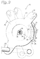
- the transmission system 15 comprises a retention device 19, which is illustrated in greater detail in Figures 2, 3 and 4.
- the retention device 19 comprises a rotatable transmission member 20, which is mounted so that it can turn about an axis designated by 21 in Figure 3.
- the rotatable transmission member 20 is made up of a body made of injection-moulded plastic material. In the embodiment illustrated in the figures, the rotatable transmission member 20 is mounted on the supporting structure 11.
- the rotatable transmission member 20 has a circular wall 22, which engages in a rotatable way a corresponding circular wall 23 formed integrally with the supporting structure 11.
- the engagement between the circular walls 22 and 23 forms a rotational guide for the rotatable transmission member 20.
- the retention device 19 is provided with means that constrain the rotatable transmission member 20 with respect to the supporting structure 11 in the direction of the axis of rotation 21.
- the said means of constraint comprise a portion having the shape of a pin 24 formed integrally with the supporting structure 11 and extending coaxially with respect to the axis of rotation 21.
- the pin-shaped portion 24 engages a hole 25 of the transmission member 20.
- the pin-shaped portion 24 has a radial projection 26, which engages by snap action the hole 25 so that the rotatable transmission member 20 is axially constrained with respect to the pin-shaped portion 24 but can rotate freely about the axis 21.
- a screw (not illustrated) could be used for axially constraining the rotatable transmission member 20 to the supporting structure 11.
- the retention device 19 comprises two arched walls 27, which define a retention groove 28 extending along a sector of a circle that is coaxial with respect to the axis of rotation 21 of the rotatable transmission member 20.
- the arched walls 27 are preferably formed integrally with the supporting structure 11.
- the groove 28 is preferably provided with a plurality of retention notches 30, which define a plurality of angular retention positions of the rotatable transmission member 20 with respect to the stationary supporting structure 11.
- the rotatable transmission member 20 is provided with an engagement member having the shape of a pin 31 housed in the groove 28.
- the engagement member 31 is preferably made integrally with the rotatable transmission member 20 and has the shape of a pin with axis parallel to the axis of rotation 21.
- the retention device 19 may also be provided with a pair of end-of-travel projections 32, which delimit the groove 28.
- the rotatable transmission member 20 has two radial appendages 33, 34 provided with respective holes.
- the appendage 33 is connected to the control tie rod 16, and the appendage 34 is connected to the end of a flexible transmission cable of a Bowden type, the other end of which is connected to the tap 13.
- the radial appendage 34 is connected to the oscillating door 14.
- the arched walls 27, which form the groove 28, have a certain degree of elasticity so as to be able to receive the pin 31 with a certain degree of interference, in such a way that the rotatable transmission member 20 is withheld in a stable position when the pin 31 comes to occupy a position corresponding to the retention notches 30.
- the pin-shaped engagement member 31 encounters the subsequent pair of retention notches 30, it snaps into engagement with said notches, indicating to the user that a new position of pre-set adjustment has been reached.
- the variation of angular position of the rotatable transmission member 20 causes a variation in the degree of opening of the tap 13 or a variation in the angular position of the door 14.
- the retention device 19 consists of a single component, i.e., the rotatable transmission member 20, which co-operates with walls made monolithically with the supporting structure 11.
- the assembly of this component is particularly simple and rapid since it does not involve any installation of balls, springs or other elements for performing the action of retention on the rotatable transmission member 20.
- the rotatable transmission member 20 may be mounted on the supporting structure 11 of the assembly 10 as illustrated in the figures. Alternatively, the rotatable transmission member 20 could be integrated in a rotatable control knob set on the control panel of the vehicle.
- the retention device 19 may be used in any transmission system associated to control means for controlling the flow of air of an air-treatment assembly for a vehicle.
- the retention device 19 may be used for remote control of the means that control the temperature of the flow of air or else on the transmission systems that carry out remote control of the position of the doors for distribution or mixing of the flow of air, or on the transmission system which controls the air intake of the assembly (intaken from outside or recirculating air).
Landscapes
- Physics & Mathematics (AREA)
- Thermal Sciences (AREA)
- Engineering & Computer Science (AREA)
- Mechanical Engineering (AREA)
- Air-Conditioning For Vehicles (AREA)
- Catching Or Destruction (AREA)
- Mechanical Control Devices (AREA)
- General Details Of Gearings (AREA)
Abstract
- a supporting structure (11) carrying at least one heat exchanger (12) for treatment of a flow of air;
- control means (13, 14), for controlling the temperature and/or the distribution and/or mixing and/or air intake of the flow of air; and
- at least one transmission system (15) comprising a retention device (19) for withholding said control means (13, 14) in a plurality of stable positions.
- a rotatable transmission member (20);
- at least one pair of walls (27) forming an arched groove (28) that is concentric with respect to the axis of rotation (21) of the rotatable transmission member(20); and
- at least one engagement member (31), fixed to the rotatable transmission member (20) and mobile within said arched groove (28).
Description
- The present invention relates to an air-flow-treatment assembly for a vehicle, having the characteristics forming the subject of the preamble of the main claim.
- An air-treatment assembly for a vehicle normally comprises a supporting structure, which carries at least one heat exchanger, and control means for controlling the flow of air, for controlling the temperature and/or air-flow distribution. The means for regulating the temperature frequently comprise a valve which regulates the rate of a flow of hot water that traverses a heat exchanger for heating the air flow. The means for regulating mixing, distribution and intake of the flow of air comprise one or more mobile doors, which according to their position vary the direction of air-flow distribution, carry out mixing of the flow of air, or vary the intake position of the flow of air to be treated (intaken from outside recirculating air). The said control means for controlling the flow of air are associated to a transmission system including rigid or flexible transmission members, which connect the control means for controlling the flow of air of the distribution assembly with control knobs or control levers, which are located on the control panel of the vehicle and which can be operated manually by the user.
- The transmission system for remote control of the means for controlling the flow of air is frequently provided with a retention device for withholding the means for controlling the flow of air in a plurality of stable positions. In known solutions, the said retention device is usually associated to the knobs of the control panel. In some known solutions, the said retention devices enable a movement to be obtained by snap action of the control knobs and envisage the use of balls associated to springs in compression, which co-operate by snap action with retention seats formed on the control knob or on cylindrical elements fixed to the control knobs.
- The object of the present invention is to provide an assembly of an improved type for treating a flow of air, in which the retention device for withholding the means for controlling the flow of air in a plurality of stable positions is made up of a small number of components that can be assembled in a simple and fast way.
- According to the present invention, this object is achieved by an assembly having the characteristics forming the subject of the main claim.
- The present invention will now be described in detail with reference to the attached drawings, which are provided purely by way of non-limiting example and in which:
- Figure 1 is a schematic perspective view of an air-treatment assembly for a vehicle;
- Figure 2 is a view at a larger scale of the retention device indicated by the arrow II in Figure 1;
- Figure 3 is a cross section taken along the line III-III of Figure 1;
- Figure 4 is a cross section taken along the line IV-IV of Figure 3; and
- Figure 5 is a perspective view illustrating the retention device of Figures 2 to 4 used for controlling an oscillating door.
- With reference to Figure 1, the
number 10 designates an assembly for treating a flow of air for a vehicle. Theassembly 10 comprises a supporting structure made of plastic material 11 forming a casing, in which there are defined chambers and ducts for treatment, mixing and distribution of a flow of air that is to be sent into the passenger compartment of a vehicle (not illustrated). The supporting structure 11 carries at least oneheat exchanger 12 for treatment of the flow of air. In particular, theheat exchanger 12 illustrated in Figure 1 is provided for the heating of the flow of air. Theheat exchanger 12 is connected to avalve 13 for regulating the rate of a flow of hot water that traverses theheat exchanger 12. - The
assembly 10 comprises means for controlling the flow of air, which are designed to regulate the temperature of the flow of air and/or the distribution, mixing and air intake of the flow. The figures show two examples of the control means for controlling the flow of air. In the example illustrated in Figure 1, the control means comprise thevalve 13, which enables regulation of the temperature of the flow of air by varying the rate of the flow of hot water that traverses theheat exchanger 12. In the example illustrated in Figure 5, the means for controlling the flow of air comprise an oscillatingdoor 14, which can control air-flow distribution, the mixing of the flow, or the air intake of the assembly (intake from outside or recirculating air). - With reference to Figure 1, the
valve 13 is controlled by atransmission system 15 including atie rod 16, which carries at its end an actuatingknob 17 located in the passenger compartment of the vehicle, by means of which the user can move the tie rod in the direction indicated by the double-headed arrow 18. Thetransmission system 15 comprises aretention device 19, which is illustrated in greater detail in Figures 2, 3 and 4. Theretention device 19 comprises arotatable transmission member 20, which is mounted so that it can turn about an axis designated by 21 in Figure 3. Therotatable transmission member 20 is made up of a body made of injection-moulded plastic material. In the embodiment illustrated in the figures, therotatable transmission member 20 is mounted on the supporting structure 11. - In the example of embodiment illustrated, the
rotatable transmission member 20 has acircular wall 22, which engages in a rotatable way a correspondingcircular wall 23 formed integrally with the supporting structure 11. The engagement between thecircular walls rotatable transmission member 20. Theretention device 19 is provided with means that constrain therotatable transmission member 20 with respect to the supporting structure 11 in the direction of the axis ofrotation 21. In the example illustrated herein, the said means of constraint comprise a portion having the shape of apin 24 formed integrally with the supporting structure 11 and extending coaxially with respect to the axis ofrotation 21. The pin-shaped portion 24 engages ahole 25 of thetransmission member 20. In the example illustrated in the figures, the pin-shaped portion 24 has aradial projection 26, which engages by snap action thehole 25 so that therotatable transmission member 20 is axially constrained with respect to the pin-shaped portion 24 but can rotate freely about theaxis 21. Alternatively, a screw (not illustrated) could be used for axially constraining therotatable transmission member 20 to the supporting structure 11. Theretention device 19 comprises twoarched walls 27, which define aretention groove 28 extending along a sector of a circle that is coaxial with respect to the axis ofrotation 21 of therotatable transmission member 20. Thearched walls 27 are preferably formed integrally with the supporting structure 11. Thegroove 28 is preferably provided with a plurality ofretention notches 30, which define a plurality of angular retention positions of therotatable transmission member 20 with respect to the stationary supporting structure 11. Therotatable transmission member 20 is provided with an engagement member having the shape of apin 31 housed in thegroove 28. Theengagement member 31 is preferably made integrally with therotatable transmission member 20 and has the shape of a pin with axis parallel to the axis ofrotation 21. As illustrated in Figure 4, theretention device 19 may also be provided with a pair of end-of-travel projections 32, which delimit thegroove 28. - The
rotatable transmission member 20 has tworadial appendages appendage 33 is connected to thecontrol tie rod 16, and theappendage 34 is connected to the end of a flexible transmission cable of a Bowden type, the other end of which is connected to thetap 13. In the variant illustrated in Figure 5, theradial appendage 34 is connected to the oscillatingdoor 14. - The
arched walls 27, which form thegroove 28, have a certain degree of elasticity so as to be able to receive thepin 31 with a certain degree of interference, in such a way that therotatable transmission member 20 is withheld in a stable position when thepin 31 comes to occupy a position corresponding to theretention notches 30. To make thetransmission member 20 rotate about its own axis ofrotation 21, it is necessary to apply, by means of thetie rod 16, a pre-set force necessary for causing theretention member 31 to come out of the condition of engagement with a pair ofnotches 30. When the pin-shaped engagement member 31 encounters the subsequent pair ofretention notches 30, it snaps into engagement with said notches, indicating to the user that a new position of pre-set adjustment has been reached. The variation of angular position of therotatable transmission member 20 causes a variation in the degree of opening of thetap 13 or a variation in the angular position of thedoor 14. - The
retention device 19 according to the present invention consists of a single component, i.e., therotatable transmission member 20, which co-operates with walls made monolithically with the supporting structure 11. The assembly of this component is particularly simple and rapid since it does not involve any installation of balls, springs or other elements for performing the action of retention on therotatable transmission member 20. Therotatable transmission member 20 may be mounted on the supporting structure 11 of theassembly 10 as illustrated in the figures. Alternatively, therotatable transmission member 20 could be integrated in a rotatable control knob set on the control panel of the vehicle. - The
retention device 19 may be used in any transmission system associated to control means for controlling the flow of air of an air-treatment assembly for a vehicle. In particular, theretention device 19 may be used for remote control of the means that control the temperature of the flow of air or else on the transmission systems that carry out remote control of the position of the doors for distribution or mixing of the flow of air, or on the transmission system which controls the air intake of the assembly (intaken from outside or recirculating air).
Claims (7)
- An air-flow-treatment assembly for a vehicle, comprising:characterized in that said retention device (19) comprises:a supporting structure (11) carrying at least one heat exchanger (12) for treatment of a flow of air;air flow control means (13, 14) for controlling the temperature and/or of the distribution and/or mixing and/or air intake of the flow of air; andat least one transmission system (15) comprising a retention device (19) for withholding said air flow control (13, 14) in a plurality of stable positions,a rotatable transmission member (20);at least one pair of walls (27) forming an arched groove (28) that is concentric with respect to the axis of rotation (21) of the rotatable transmission member (20); andat least one engagement member (31), fixed to the rotatable transmission member (20) and mobile within said arched groove (28).
- The assembly according to Claim 1, characterized in that said walls (27) are provided with a plurality of retention notches (30) defining positions of stable engagement of said rotatable transmission member (20).
- The assembly according to Claim 1 or Claim 2, characterized in that the rotatable transmission member (20) comprises a pair of radial appendages (33, 34), one first one of which (33) is connected to a control tie rod, which can be operated manually (16).
- The assembly according to Claim 3, characterized in that the second of said radial appendages (34) is connected to a flexible transmission cable (35).
- The assembly according to Claim 3, characterized in that the second of said radial appendages (34) is connected to an oscillating door (14).
- The assembly according to Claim 1, characterized in that the rotatable transmission member (20) comprises a circular wall (22), which engages, in a rotatable way, a wall of a stationary guide (23).
- The assembly according to Claim 1, characterized in that it comprises means for constraint of the rotatable transmission member (20) in the direction of its own axis of rotation (21).
Priority Applications (4)
| Application Number | Priority Date | Filing Date | Title |
|---|---|---|---|
| ES02425772T ES2239215T3 (en) | 2002-12-13 | 2002-12-13 | ASSEMBLY FOR THE TREATMENT OF AIR FLOW FOR A VEHICLE THAT INCLUDES A TRANSMISSION SYSTEM FOR REMOTE CONTROL OF THE AIR FLOW CONTROL MEANS. |
| AT02425772T ATE295787T1 (en) | 2002-12-13 | 2002-12-13 | DEVICE FOR TREATING AN AIR FLOW IN A VEHICLE HAVING A TRANSMISSION SYSTEM FOR CONTROLLING THE MEANS FOR CONTROLLING THE AIR FLOW |
| DE60204230T DE60204230T2 (en) | 2002-12-13 | 2002-12-13 | Apparatus for treating an air flow in a vehicle with a transmission system for controlling the means for controlling the air flow |
| EP02425772A EP1428700B1 (en) | 2002-12-13 | 2002-12-13 | Air flow treatment assembly for a vehicle comprising a transmission system for remote control of the means for controlling the flow of air |
Applications Claiming Priority (1)
| Application Number | Priority Date | Filing Date | Title |
|---|---|---|---|
| EP02425772A EP1428700B1 (en) | 2002-12-13 | 2002-12-13 | Air flow treatment assembly for a vehicle comprising a transmission system for remote control of the means for controlling the flow of air |
Publications (2)
| Publication Number | Publication Date |
|---|---|
| EP1428700A1 true EP1428700A1 (en) | 2004-06-16 |
| EP1428700B1 EP1428700B1 (en) | 2005-05-18 |
Family
ID=32319744
Family Applications (1)
| Application Number | Title | Priority Date | Filing Date |
|---|---|---|---|
| EP02425772A Expired - Lifetime EP1428700B1 (en) | 2002-12-13 | 2002-12-13 | Air flow treatment assembly for a vehicle comprising a transmission system for remote control of the means for controlling the flow of air |
Country Status (4)
| Country | Link |
|---|---|
| EP (1) | EP1428700B1 (en) |
| AT (1) | ATE295787T1 (en) |
| DE (1) | DE60204230T2 (en) |
| ES (1) | ES2239215T3 (en) |
Citations (2)
| Publication number | Priority date | Publication date | Assignee | Title |
|---|---|---|---|---|
| US4653386A (en) * | 1984-11-20 | 1987-03-31 | Toyota Jidosha Kabushiki Kaisha | Wind direction adjusting mechanism for air conditioner |
| EP1213165A2 (en) * | 2000-12-06 | 2002-06-12 | Kabushiki Kaisha Tokai-Rika-Denki-Seisakusho | Operation switch unit for vehicle |
-
2002
- 2002-12-13 ES ES02425772T patent/ES2239215T3/en not_active Expired - Lifetime
- 2002-12-13 EP EP02425772A patent/EP1428700B1/en not_active Expired - Lifetime
- 2002-12-13 AT AT02425772T patent/ATE295787T1/en not_active IP Right Cessation
- 2002-12-13 DE DE60204230T patent/DE60204230T2/en not_active Expired - Lifetime
Patent Citations (2)
| Publication number | Priority date | Publication date | Assignee | Title |
|---|---|---|---|---|
| US4653386A (en) * | 1984-11-20 | 1987-03-31 | Toyota Jidosha Kabushiki Kaisha | Wind direction adjusting mechanism for air conditioner |
| EP1213165A2 (en) * | 2000-12-06 | 2002-06-12 | Kabushiki Kaisha Tokai-Rika-Denki-Seisakusho | Operation switch unit for vehicle |
Also Published As
| Publication number | Publication date |
|---|---|
| DE60204230T2 (en) | 2005-11-10 |
| ATE295787T1 (en) | 2005-06-15 |
| EP1428700B1 (en) | 2005-05-18 |
| ES2239215T3 (en) | 2005-09-16 |
| DE60204230D1 (en) | 2005-06-23 |
Similar Documents
| Publication | Publication Date | Title |
|---|---|---|
| JPH06193691A (en) | Rotational temperature controller | |
| US5245886A (en) | Rotary temperature mechanism | |
| KR100427634B1 (en) | A vent grill for vehicle | |
| KR102269827B1 (en) | Air vent for vehicle | |
| EP3665023B1 (en) | Air ventilator for an automobile | |
| KR20140126604A (en) | The Airbent of Vehicle | |
| EP1428700A1 (en) | Air flow treatment assembly for a vehicle comprising a transmission system for remote control of the means for controlling the flow of air | |
| CN101539325B (en) | Rotary switch assembly for air conditioner in vehicle | |
| EP2014490B1 (en) | Rotating control assembly with double cable | |
| JP2004299540A (en) | Link drive mechanism of vehicle air conditioner | |
| US5433126A (en) | Rotary controlled motion transmission assembly | |
| KR20060009183A (en) | Car air vent regulator | |
| KR20130041481A (en) | Positioning apparatus of cam plate for air conditioning system in vehicle | |
| EP0834410B1 (en) | Sliding structure for manual control member | |
| KR20100034526A (en) | Device for opening and closing air vent | |
| KR20090022498A (en) | Vehicle air conditioning system | |
| KR100613710B1 (en) | Car air vent structure | |
| KR101666459B1 (en) | Auto-lotation equipment for air-vent | |
| JP4000667B2 (en) | Air conditioner for vehicles | |
| KR20040049377A (en) | Structure of air vent for vehicle | |
| KR20040033850A (en) | Bent grille for an automobile | |
| JP6641622B2 (en) | Dial control operation device | |
| KR20090102156A (en) | Device for opening and closing air vent | |
| CN111692645B (en) | Air guide device and air conditioner | |
| RU43500U1 (en) | VEHICLE HEATER INSTALLATION CONTROL UNIT |
Legal Events
| Date | Code | Title | Description |
|---|---|---|---|
| PUAI | Public reference made under article 153(3) epc to a published international application that has entered the european phase |
Free format text: ORIGINAL CODE: 0009012 |
|
| AK | Designated contracting states |
Kind code of ref document: A1 Designated state(s): AT BE BG CH CY CZ DE DK EE ES FI FR GB GR IE IT LI LU MC NL PT SE SI SK TR |
|
| AX | Request for extension of the european patent |
Extension state: AL LT LV MK RO |
|
| 17P | Request for examination filed |
Effective date: 20040512 |
|
| 17Q | First examination report despatched |
Effective date: 20040607 |
|
| GRAP | Despatch of communication of intention to grant a patent |
Free format text: ORIGINAL CODE: EPIDOSNIGR1 |
|
| AKX | Designation fees paid |
Designated state(s): AT BE BG CH CY CZ DE DK EE ES FI FR GB GR IE IT LI LU MC NL PT SE SI SK TR |
|
| GRAS | Grant fee paid |
Free format text: ORIGINAL CODE: EPIDOSNIGR3 |
|
| GRAA | (expected) grant |
Free format text: ORIGINAL CODE: 0009210 |
|
| AK | Designated contracting states |
Kind code of ref document: B1 Designated state(s): AT BE BG CH CY CZ DE DK EE ES FI FR GB GR IE IT LI LU MC NL PT SE SI SK TR |
|
| PG25 | Lapsed in a contracting state [announced via postgrant information from national office to epo] |
Ref country code: CZ Free format text: LAPSE BECAUSE OF FAILURE TO SUBMIT A TRANSLATION OF THE DESCRIPTION OR TO PAY THE FEE WITHIN THE PRESCRIBED TIME-LIMIT Effective date: 20050518 Ref country code: SI Free format text: LAPSE BECAUSE OF FAILURE TO SUBMIT A TRANSLATION OF THE DESCRIPTION OR TO PAY THE FEE WITHIN THE PRESCRIBED TIME-LIMIT Effective date: 20050518 Ref country code: EE Free format text: LAPSE BECAUSE OF FAILURE TO SUBMIT A TRANSLATION OF THE DESCRIPTION OR TO PAY THE FEE WITHIN THE PRESCRIBED TIME-LIMIT Effective date: 20050518 Ref country code: FI Free format text: LAPSE BECAUSE OF FAILURE TO SUBMIT A TRANSLATION OF THE DESCRIPTION OR TO PAY THE FEE WITHIN THE PRESCRIBED TIME-LIMIT Effective date: 20050518 Ref country code: LI Free format text: LAPSE BECAUSE OF FAILURE TO SUBMIT A TRANSLATION OF THE DESCRIPTION OR TO PAY THE FEE WITHIN THE PRESCRIBED TIME-LIMIT Effective date: 20050518 Ref country code: SK Free format text: LAPSE BECAUSE OF FAILURE TO SUBMIT A TRANSLATION OF THE DESCRIPTION OR TO PAY THE FEE WITHIN THE PRESCRIBED TIME-LIMIT Effective date: 20050518 Ref country code: AT Free format text: LAPSE BECAUSE OF FAILURE TO SUBMIT A TRANSLATION OF THE DESCRIPTION OR TO PAY THE FEE WITHIN THE PRESCRIBED TIME-LIMIT Effective date: 20050518 Ref country code: BE Free format text: LAPSE BECAUSE OF FAILURE TO SUBMIT A TRANSLATION OF THE DESCRIPTION OR TO PAY THE FEE WITHIN THE PRESCRIBED TIME-LIMIT Effective date: 20050518 Ref country code: NL Free format text: LAPSE BECAUSE OF FAILURE TO SUBMIT A TRANSLATION OF THE DESCRIPTION OR TO PAY THE FEE WITHIN THE PRESCRIBED TIME-LIMIT Effective date: 20050518 Ref country code: CH Free format text: LAPSE BECAUSE OF FAILURE TO SUBMIT A TRANSLATION OF THE DESCRIPTION OR TO PAY THE FEE WITHIN THE PRESCRIBED TIME-LIMIT Effective date: 20050518 |
|
| REG | Reference to a national code |
Ref country code: GB Ref legal event code: FG4D |
|
| REG | Reference to a national code |
Ref country code: CH Ref legal event code: EP |
|
| REG | Reference to a national code |
Ref country code: IE Ref legal event code: FG4D |
|
| REF | Corresponds to: |
Ref document number: 60204230 Country of ref document: DE Date of ref document: 20050623 Kind code of ref document: P |
|
| REG | Reference to a national code |
Ref country code: SE Ref legal event code: TRGR |
|
| PG25 | Lapsed in a contracting state [announced via postgrant information from national office to epo] |
Ref country code: BG Free format text: LAPSE BECAUSE OF FAILURE TO SUBMIT A TRANSLATION OF THE DESCRIPTION OR TO PAY THE FEE WITHIN THE PRESCRIBED TIME-LIMIT Effective date: 20050818 Ref country code: DK Free format text: LAPSE BECAUSE OF FAILURE TO SUBMIT A TRANSLATION OF THE DESCRIPTION OR TO PAY THE FEE WITHIN THE PRESCRIBED TIME-LIMIT Effective date: 20050818 Ref country code: GR Free format text: LAPSE BECAUSE OF FAILURE TO SUBMIT A TRANSLATION OF THE DESCRIPTION OR TO PAY THE FEE WITHIN THE PRESCRIBED TIME-LIMIT Effective date: 20050818 |
|
| REG | Reference to a national code |
Ref country code: ES Ref legal event code: FG2A Ref document number: 2239215 Country of ref document: ES Kind code of ref document: T3 |
|
| PG25 | Lapsed in a contracting state [announced via postgrant information from national office to epo] |
Ref country code: PT Free format text: LAPSE BECAUSE OF FAILURE TO SUBMIT A TRANSLATION OF THE DESCRIPTION OR TO PAY THE FEE WITHIN THE PRESCRIBED TIME-LIMIT Effective date: 20051024 |
|
| REG | Reference to a national code |
Ref country code: CH Ref legal event code: PL |
|
| NLV1 | Nl: lapsed or annulled due to failure to fulfill the requirements of art. 29p and 29m of the patents act | ||
| PG25 | Lapsed in a contracting state [announced via postgrant information from national office to epo] |
Ref country code: IE Free format text: LAPSE BECAUSE OF NON-PAYMENT OF DUE FEES Effective date: 20051213 Ref country code: CY Free format text: LAPSE BECAUSE OF FAILURE TO SUBMIT A TRANSLATION OF THE DESCRIPTION OR TO PAY THE FEE WITHIN THE PRESCRIBED TIME-LIMIT Effective date: 20051213 |
|
| PG25 | Lapsed in a contracting state [announced via postgrant information from national office to epo] |
Ref country code: MC Free format text: LAPSE BECAUSE OF NON-PAYMENT OF DUE FEES Effective date: 20051231 Ref country code: LU Free format text: LAPSE BECAUSE OF NON-PAYMENT OF DUE FEES Effective date: 20051231 |
|
| ET | Fr: translation filed | ||
| PLBE | No opposition filed within time limit |
Free format text: ORIGINAL CODE: 0009261 |
|
| STAA | Information on the status of an ep patent application or granted ep patent |
Free format text: STATUS: NO OPPOSITION FILED WITHIN TIME LIMIT |
|
| 26N | No opposition filed |
Effective date: 20060221 |
|
| REG | Reference to a national code |
Ref country code: IE Ref legal event code: MM4A |
|
| PGFP | Annual fee paid to national office [announced via postgrant information from national office to epo] |
Ref country code: SE Payment date: 20101221 Year of fee payment: 9 Ref country code: TR Payment date: 20101126 Year of fee payment: 9 Ref country code: GB Payment date: 20101221 Year of fee payment: 9 Ref country code: IT Payment date: 20101218 Year of fee payment: 9 |
|
| PGFP | Annual fee paid to national office [announced via postgrant information from national office to epo] |
Ref country code: DE Payment date: 20101222 Year of fee payment: 9 |
|
| PGFP | Annual fee paid to national office [announced via postgrant information from national office to epo] |
Ref country code: ES Payment date: 20101221 Year of fee payment: 9 |
|
| PGFP | Annual fee paid to national office [announced via postgrant information from national office to epo] |
Ref country code: FR Payment date: 20120118 Year of fee payment: 10 |
|
| REG | Reference to a national code |
Ref country code: SE Ref legal event code: EUG |
|
| GBPC | Gb: european patent ceased through non-payment of renewal fee |
Effective date: 20111213 |
|
| REG | Reference to a national code |
Ref country code: DE Ref legal event code: R119 Ref document number: 60204230 Country of ref document: DE Effective date: 20120703 |
|
| PG25 | Lapsed in a contracting state [announced via postgrant information from national office to epo] |
Ref country code: DE Free format text: LAPSE BECAUSE OF NON-PAYMENT OF DUE FEES Effective date: 20120703 Ref country code: SE Free format text: LAPSE BECAUSE OF NON-PAYMENT OF DUE FEES Effective date: 20111214 Ref country code: GB Free format text: LAPSE BECAUSE OF NON-PAYMENT OF DUE FEES Effective date: 20111213 |
|
| REG | Reference to a national code |
Ref country code: ES Ref legal event code: FD2A Effective date: 20130704 |
|
| PG25 | Lapsed in a contracting state [announced via postgrant information from national office to epo] |
Ref country code: ES Free format text: LAPSE BECAUSE OF NON-PAYMENT OF DUE FEES Effective date: 20111214 |
|
| REG | Reference to a national code |
Ref country code: FR Ref legal event code: ST Effective date: 20130830 |
|
| PG25 | Lapsed in a contracting state [announced via postgrant information from national office to epo] |
Ref country code: TR Free format text: LAPSE BECAUSE OF NON-PAYMENT OF DUE FEES Effective date: 20111213 |
|
| PG25 | Lapsed in a contracting state [announced via postgrant information from national office to epo] |
Ref country code: FR Free format text: LAPSE BECAUSE OF NON-PAYMENT OF DUE FEES Effective date: 20130102 |
|
| PG25 | Lapsed in a contracting state [announced via postgrant information from national office to epo] |
Ref country code: IT Free format text: LAPSE BECAUSE OF NON-PAYMENT OF DUE FEES Effective date: 20121213 |