EP1428699A1 - Control unit for an air distribution and treatment assembly for vehicles - Google Patents
Control unit for an air distribution and treatment assembly for vehicles Download PDFInfo
- Publication number
- EP1428699A1 EP1428699A1 EP02425771A EP02425771A EP1428699A1 EP 1428699 A1 EP1428699 A1 EP 1428699A1 EP 02425771 A EP02425771 A EP 02425771A EP 02425771 A EP02425771 A EP 02425771A EP 1428699 A1 EP1428699 A1 EP 1428699A1
- Authority
- EP
- European Patent Office
- Prior art keywords
- supporting
- tubular sleeve
- control unit
- external
- casing
- Prior art date
- Legal status (The legal status is an assumption and is not a legal conclusion. Google has not performed a legal analysis and makes no representation as to the accuracy of the status listed.)
- Granted
Links
Images
Classifications
-
- G—PHYSICS
- G05—CONTROLLING; REGULATING
- G05G—CONTROL DEVICES OR SYSTEMS INSOFAR AS CHARACTERISED BY MECHANICAL FEATURES ONLY
- G05G1/00—Controlling members, e.g. knobs or handles; Assemblies or arrangements thereof; Indicating position of controlling members
- G05G1/08—Controlling members for hand actuation by rotary movement, e.g. hand wheels
- G05G1/10—Details, e.g. of discs, knobs, wheels or handles
-
- B—PERFORMING OPERATIONS; TRANSPORTING
- B60—VEHICLES IN GENERAL
- B60H—ARRANGEMENTS OF HEATING, COOLING, VENTILATING OR OTHER AIR-TREATING DEVICES SPECIALLY ADAPTED FOR PASSENGER OR GOODS SPACES OF VEHICLES
- B60H1/00—Heating, cooling or ventilating devices
- B60H1/00642—Control systems or circuits; Control members or indication devices for heating, cooling or ventilating devices
- B60H1/0065—Control members, e.g. levers or knobs
-
- B—PERFORMING OPERATIONS; TRANSPORTING
- B60—VEHICLES IN GENERAL
- B60H—ARRANGEMENTS OF HEATING, COOLING, VENTILATING OR OTHER AIR-TREATING DEVICES SPECIALLY ADAPTED FOR PASSENGER OR GOODS SPACES OF VEHICLES
- B60H1/00—Heating, cooling or ventilating devices
- B60H1/00642—Control systems or circuits; Control members or indication devices for heating, cooling or ventilating devices
- B60H1/00985—Control systems or circuits characterised by display or indicating devices, e.g. voice simulators
-
- H—ELECTRICITY
- H01—ELECTRIC ELEMENTS
- H01H—ELECTRIC SWITCHES; RELAYS; SELECTORS; EMERGENCY PROTECTIVE DEVICES
- H01H3/00—Mechanisms for operating contacts
- H01H3/02—Operating parts, i.e. for operating driving mechanism by a mechanical force external to the switch
- H01H2003/026—Operating parts, i.e. for operating driving mechanism by a mechanical force external to the switch specially adapted to avoid injury to occupants of a car during an accident
-
- H—ELECTRICITY
- H01—ELECTRIC ELEMENTS
- H01H—ELECTRIC SWITCHES; RELAYS; SELECTORS; EMERGENCY PROTECTIVE DEVICES
- H01H3/00—Mechanisms for operating contacts
- H01H3/02—Operating parts, i.e. for operating driving mechanism by a mechanical force external to the switch
- H01H3/08—Turn knobs
- H01H2003/085—Retractable turn knobs, e.g. flush mounted
-
- H—ELECTRICITY
- H01—ELECTRIC ELEMENTS
- H01H—ELECTRIC SWITCHES; RELAYS; SELECTORS; EMERGENCY PROTECTIVE DEVICES
- H01H19/00—Switches operated by an operating part which is rotatable about a longitudinal axis thereof and which is acted upon directly by a solid body external to the switch, e.g. by a hand
- H01H19/02—Details
- H01H19/10—Movable parts; Contacts mounted thereon
- H01H19/14—Operating parts, e.g. turn knob
- H01H2019/143—Operating parts, e.g. turn knob having at least two concentric turn knobs
Definitions
- the present invention relates to a control unit for an air-distribution-and-treatment assembly for vehicles.
- the document US-A-4995554 describes a control unit for an air-distribution-and-treatment assembly for vehicles, having the characteristics forming the subject of the preamble of the main claim.
- This document describes a control unit comprising a casing with two coaxial rotary control knobs which project outside the casing and two coaxial shafts fixed in rotation to the two knobs.
- the two knobs have the purpose of controlling the temperature and distribution of a flow of air inside a vehicle.
- the control unit is also provided with a fixed intermediate sleeve set between the two control shafts for preventing any interaction between the two control knobs.
- a control unit with two coaxial rotating knobs must have the knobs of dimensions sufficiently large for them to be gripped and rotated easily by the user.
- the fact of providing knobs projecting from a front surface of the dashboard of a vehicle represents a problem from the point of view of safety.
- any rigid projecting bodies located in front of the driver or passenger in order to reduce any risk of injury to the occupants of the vehicle in the event of accident.
- the purpose of the present invention is to provide a control unit with coaxial rotating knobs for an assembly for treating and distributing air for vehicles which will enable greater guarantees to be obtained from the point of view of safety of the occupants of the vehicle.
- control unit having the characteristics forming the subject of the main claim.
- the number 10 designates a control unit for an air-distribution-and-treatment assembly for vehicles.
- the control unit 10 comprises a substantially box-shaped casing 12 designed to be fixed to a front wall of the dashboard of a vehicle (not illustrated).
- the casing 12 comprises a front panel 14 provided with two circular openings 16, through which there project two rotating control assemblies 18, 20.
- Each control assembly 18, 20 comprises an external rotating knob 22 and an internal rotating knob 24 set coaxially with respect to one another.
- the front panel 14 has, at each control assembly 19, 20, two sets of graphic indications.
- the graphic indications for the control assembly 18 are designated by 26 and 28 and indicate, respectively, the temperature selected of the flow of air and the speed of rotation of the electric fan.
- the graphic indications for the control assembly 20 are designated, respectively, by 30 and 32 and refer, respectively, to the air-flow distribution and the intake of the flow (circulating air or external air intake).
- the external knob 22 of the control assembly 18 controls the temperature of the flow of air
- the internal knob 24 controls the speed of rotation of the electric fan.
- the external knob 22 of the control assembly 20 controls the air-flow distribution inside the passenger compartment, and the internal knob 24 of the control assembly 20 controls the position of intake of the flow (circulating air or external air intake).
- control panel 14 there may be provided seats 34, 36 and 38 for electrical control switches, for example for controlling the emergency lights of the vehicle, for activation and de-activation of the compressor of the air-conditioning system, and for controlling the device for defrosting the rear window, respectively.
- the casing 12 comprises a supporting wall 40 having a through opening 42, through which there extends a supporting tubular sleeve 44 preferably made of injection-moulded plastic material.
- the tubular sleeve 44 is provided with elastically deformable portions 46, which engage the through opening 42.
- Each of the elastically deformable portions 46 is provided with a tooth 48, which interferes with a front edge of the through opening 42.
- the rotary control assembly 18 comprises an external control shaft 50 and an internal control shaft 52.
- the external control shaft is mounted so that it can turn on an external surface 52 of the supporting tubular sleeve 44 and is fixed, for example by means of snap-action fit, to the external knob 22.
- the internal control shaft 52 is supported in rotation by an internal surface 56 of the tubular sleeve 44 and is fixed, for example by means of snap-action fit, to the internal knob 24.
- the control shafts 50, 52 are connected to respective control or adjustment devices (not illustrated), which do not fall within the scope of the present invention.
- the box-like casing 12 comprises a front supporting wall 58 having an opening 60, within which is supported in rotation the external control shaft 50.
- Figure 2 illustrates the position of normal use of the unit 10. In this condition, the knobs 22 and 24 project outside the front panel 14 and are freely rotatable independently of one another about their common axis A. The supporting tubular sleeve 44 in this condition is fixed with respect to the casing 12.
- the supporting sleeve 44 is connected to the supporting casing 12 so as to be able to move along the axis A under the action of a force having a pre-set value.
- a force having a pre-set value As illustrated in Figure 3, when an axial force F of a value higher than the pre-set threshold value acts upon the rotating knobs 22, 24, the entire control assembly 18 made up of the knobs 22, 24, the control shafts 50, 52, and the supporting tubular sleeve 44 moves in the direction of the force F.
- the sleeve 44 is disengaged from the opening 42 when the axial force F overcomes the elastic resistance of the elastically deformable portions 46 necessary for causing the teeth 48 to pass inside the opening 42.
- control assembly 18 is built so as to shift backwards under the force F, without causing failure of any component.
- functionality of the assembly can be re-established by pushing forward the supporting sleeve 44 and without the need for replacing parts or components.
- control unit enables an increase in safety both for the driver and for the passengers of the vehicle since it reduces the risk of injury or bruises following upon accidents caused by bumping against projecting parts of the dashboard.
- the force necessary for shifting the rotating knobs backwards inside the casing is determined so that the knobs 22, 24 can shift backwards only following upon impact that is able to injure an occupant of the vehicle in the event of failure of the assembly to shift backwards.
Landscapes
- Physics & Mathematics (AREA)
- Engineering & Computer Science (AREA)
- Thermal Sciences (AREA)
- Mechanical Engineering (AREA)
- General Physics & Mathematics (AREA)
- Automation & Control Theory (AREA)
- Air-Conditioning For Vehicles (AREA)
- Mechanical Control Devices (AREA)
- Air-Flow Control Members (AREA)
- Flow Control (AREA)
- Air Bags (AREA)
Abstract
- a supporting casing (12);
- a supporting tubular sleeve (44), connected to the supporting casing (12);
- an external rotating knob (22) and an internal rotating knob (24), set coaxial with respect to one another;
- an external control shaft (50), which is mounted so that it can turn on an external surface (54) of the supporting tubular sleeve (44) and is fixed to the external rotating knob (22); and
- an internal control shaft (52), which is mounted so that it can turn on an internal surface (56) of the supporting tubular sleeve (44) and is fixed to the internal rotating knob (24).
Description
- The present invention relates to a control unit for an air-distribution-and-treatment assembly for vehicles.
- The document US-A-4995554 describes a control unit for an air-distribution-and-treatment assembly for vehicles, having the characteristics forming the subject of the preamble of the main claim. This document describes a control unit comprising a casing with two coaxial rotary control knobs which project outside the casing and two coaxial shafts fixed in rotation to the two knobs. The two knobs have the purpose of controlling the temperature and distribution of a flow of air inside a vehicle. The control unit is also provided with a fixed intermediate sleeve set between the two control shafts for preventing any interaction between the two control knobs.
- A control unit with two coaxial rotating knobs must have the knobs of dimensions sufficiently large for them to be gripped and rotated easily by the user. The fact of providing knobs projecting from a front surface of the dashboard of a vehicle represents a problem from the point of view of safety. In fact, inside the passenger compartment of a vehicle there should not be present any rigid projecting bodies located in front of the driver or passenger, in order to reduce any risk of injury to the occupants of the vehicle in the event of accident.
- The purpose of the present invention is to provide a control unit with coaxial rotating knobs for an assembly for treating and distributing air for vehicles which will enable greater guarantees to be obtained from the point of view of safety of the occupants of the vehicle.
- According to the present invention, the said purpose is achieved by a control unit having the characteristics forming the subject of the main claim.
- The present invention will now be described in detail with reference to the attached drawings, which are provided purely by way of non-limiting example and in which:
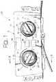
- Figure 1 is a front elevation of a control unit according to the present invention;
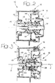
- Figure 2 is a cross section taken along the line II-II of Figure 1; and
- Figure 3 is a cross-sectional view corresponding to Figure 2 illustrating the condition in which the knobs are set back inside the casing following upon impact.
- With reference to Figure 1, the
number 10 designates a control unit for an air-distribution-and-treatment assembly for vehicles. Thecontrol unit 10 comprises a substantially box-shaped casing 12 designed to be fixed to a front wall of the dashboard of a vehicle (not illustrated). Thecasing 12 comprises afront panel 14 provided with twocircular openings 16, through which there project tworotating control assemblies control assembly rotating knob 22 and an internal rotatingknob 24 set coaxially with respect to one another. - The
front panel 14 has, at eachcontrol assembly 19, 20, two sets of graphic indications. The graphic indications for thecontrol assembly 18 are designated by 26 and 28 and indicate, respectively, the temperature selected of the flow of air and the speed of rotation of the electric fan. The graphic indications for thecontrol assembly 20 are designated, respectively, by 30 and 32 and refer, respectively, to the air-flow distribution and the intake of the flow (circulating air or external air intake). Theexternal knob 22 of thecontrol assembly 18 controls the temperature of the flow of air, and theinternal knob 24 controls the speed of rotation of the electric fan. Theexternal knob 22 of thecontrol assembly 20 controls the air-flow distribution inside the passenger compartment, and theinternal knob 24 of thecontrol assembly 20 controls the position of intake of the flow (circulating air or external air intake). - Once again with reference to Figure 1, in the
control panel 14 there may be providedseats - With reference to Figures 2 and 3, the
casing 12 comprises a supportingwall 40 having a through opening 42, through which there extends a supportingtubular sleeve 44 preferably made of injection-moulded plastic material. Thetubular sleeve 44 is provided with elasticallydeformable portions 46, which engage the through opening 42. Each of the elasticallydeformable portions 46 is provided with atooth 48, which interferes with a front edge of the through opening 42. - The
rotary control assembly 18 comprises anexternal control shaft 50 and aninternal control shaft 52. The external control shaft is mounted so that it can turn on anexternal surface 52 of the supportingtubular sleeve 44 and is fixed, for example by means of snap-action fit, to theexternal knob 22. Theinternal control shaft 52 is supported in rotation by aninternal surface 56 of thetubular sleeve 44 and is fixed, for example by means of snap-action fit, to theinternal knob 24. Thecontrol shafts - Preferably, the box-
like casing 12 comprises a front supportingwall 58 having anopening 60, within which is supported in rotation theexternal control shaft 50. Figure 2 illustrates the position of normal use of theunit 10. In this condition, theknobs front panel 14 and are freely rotatable independently of one another about their common axis A. The supportingtubular sleeve 44 in this condition is fixed with respect to thecasing 12. - According to the present invention, the supporting
sleeve 44 is connected to the supportingcasing 12 so as to be able to move along the axis A under the action of a force having a pre-set value. As illustrated in Figure 3, when an axial force F of a value higher than the pre-set threshold value acts upon the rotatingknobs entire control assembly 18 made up of theknobs control shafts tubular sleeve 44 moves in the direction of the force F. Thesleeve 44 is disengaged from theopening 42 when the axial force F overcomes the elastic resistance of the elasticallydeformable portions 46 necessary for causing theteeth 48 to pass inside theopening 42. As may be seen in Figure 3, theentire control assembly 18 is built so as to shift backwards under the force F, without causing failure of any component. Following upon impact, which has produced shifting-back of theknobs sleeve 44 and without the need for replacing parts or components. - From the foregoing description it will be readily understood that the control unit according to the present invention enables an increase in safety both for the driver and for the passengers of the vehicle since it reduces the risk of injury or bruises following upon accidents caused by bumping against projecting parts of the dashboard. The force necessary for shifting the rotating knobs backwards inside the casing is determined so that the
knobs
Claims (4)
- A control unit for an air-distribution-and-treatment assembly for vehicles, comprising:characterized in that the supporting tubular sleeve (44) is connected to the supporting casing (12) by means of connecting means (46, 48) which can be disengaged under the action of a predetermined axial force so that the assembly (18, 20) comprising the tubular sleeve (44), the rotating knobs (22, 24) and the two control shafts (50, 52) is able to move with respect to the supporting casing (12) between an extracted position and a set-in position under the action of a predetermined force (F) acting on the rotating knobs (22, 24).a supporting casing (12);a supporting tubular sleeve (44), connected to the supporting casing (12);an external rotating knob (22) and an internal rotating knob (24), set coaxial with respect to one another;an external control shaft (50), mounted so that it can turn on an external surface (54) of the supporting tubular sleeve (44) and fixed to the external rotating knob (22); andan internal control shaft (52), which is mounted so that it can turn on an internal surface (56) of the supporting tubular sleeve (44) and is fixed to the internal rotating knob (24),
- The control unit according to Claim 1, characterized in that said disengageable connecting means comprise a plurality of elastically deformable portions (46), which are integral with the tubular sleeve (44) and engage a through opening (42) of a supporting wall (40) of the supporting casing (12).
- The control unit according to Claim 2, characterized in that said elastically deformable portions (46) are provided with respective teeth (48), which establish an interference with a front edge of said through opening (42).
- The control unit according to Claim 2, characterized in that the supporting casing (12) comprises a front supporting wall (58) having a through opening (60), which is engaged in rotation by said external control shaft (50).
Priority Applications (4)
| Application Number | Priority Date | Filing Date | Title |
|---|---|---|---|
| EP02425771A EP1428699B1 (en) | 2002-12-13 | 2002-12-13 | Control unit for an air distribution and treatment assembly for vehicles |
| DE60203810T DE60203810T2 (en) | 2002-12-13 | 2002-12-13 | Control for an air distribution and treatment plant for vehicles |
| ES02425771T ES2240682T3 (en) | 2002-12-13 | 2002-12-13 | CONTROL UNIT FOR A TREATMENT AND AIR DISTRIBUTION SET FOR VEHICLES. |
| AT02425771T ATE293546T1 (en) | 2002-12-13 | 2002-12-13 | CONTROLLER FOR AN AIR DISTRIBUTION SYSTEM AND TREATMENT SYSTEM FOR VEHICLES |
Applications Claiming Priority (1)
| Application Number | Priority Date | Filing Date | Title |
|---|---|---|---|
| EP02425771A EP1428699B1 (en) | 2002-12-13 | 2002-12-13 | Control unit for an air distribution and treatment assembly for vehicles |
Publications (2)
| Publication Number | Publication Date |
|---|---|
| EP1428699A1 true EP1428699A1 (en) | 2004-06-16 |
| EP1428699B1 EP1428699B1 (en) | 2005-04-20 |
Family
ID=32319743
Family Applications (1)
| Application Number | Title | Priority Date | Filing Date |
|---|---|---|---|
| EP02425771A Expired - Lifetime EP1428699B1 (en) | 2002-12-13 | 2002-12-13 | Control unit for an air distribution and treatment assembly for vehicles |
Country Status (4)
| Country | Link |
|---|---|
| EP (1) | EP1428699B1 (en) |
| AT (1) | ATE293546T1 (en) |
| DE (1) | DE60203810T2 (en) |
| ES (1) | ES2240682T3 (en) |
Cited By (14)
| Publication number | Priority date | Publication date | Assignee | Title |
|---|---|---|---|---|
| WO2008014327A1 (en) * | 2006-07-28 | 2008-01-31 | Bose Corporation | Control knob with safety feature |
| EP1892602A1 (en) * | 2006-08-22 | 2008-02-27 | Miele & Cie. KG | Retractable knob for a domestic appliance with a mandrel to connect to an energy supply, selector switch or similar |
| EP2193942A1 (en) * | 2008-12-04 | 2010-06-09 | Delphi Technologies, Inc. | Control box equipped with a locking system for a control shaft |
| CN102192571A (en) * | 2010-03-01 | 2011-09-21 | 德尔菲技术公司 | Control unit provided with locking system for controlling shafts |
| JP2012210910A (en) * | 2011-03-31 | 2012-11-01 | Tokai Rika Co Ltd | Operating device |
| EP2341290A3 (en) * | 2009-12-25 | 2012-12-05 | BSH Bosch und Siemens Hausgeräte GmbH | A home appliance with control knob |
| EP2237297A4 (en) * | 2007-12-28 | 2013-04-24 | Pioneer Corp | Support structure for operation knob and electronic apparatus with the support structure |
| JP2015020678A (en) * | 2013-07-23 | 2015-02-02 | 株式会社ユーシン | Air conditioning operating device for vehicles. |
| FR3015709A1 (en) * | 2013-12-19 | 2015-06-26 | Peugeot Citroen Automobiles Sa | MANUAL CONTROL DEVICE WITH ROTARY CONTROL ARM WITH REDUCED GAME FOR INDUCING QUASIMENTLY NIL EFFORT |
| CN105196830A (en) * | 2015-09-11 | 2015-12-30 | 安徽江淮汽车股份有限公司 | Automobile air outlet assembly |
| CN106114223A (en) * | 2015-05-05 | 2016-11-16 | 通用汽车环球科技运作有限责任公司 | Automobile, automobile instrument and for controlling the user interface of automobile equipment |
| JP2017094907A (en) * | 2015-11-24 | 2017-06-01 | 株式会社ユーシン | Air-conditioning operation device for vehicle |
| US9937880B2 (en) | 2014-08-01 | 2018-04-10 | Dr. Ing. H.C. F. Porsche Aktiengesellschaft | Seat actuating element for a motor vehicle seat |
| WO2021116007A1 (en) * | 2019-12-12 | 2021-06-17 | Zf Friedrichshafen Ag | Operating device, vehicle and method for operating a vehicle |
Citations (3)
| Publication number | Priority date | Publication date | Assignee | Title |
|---|---|---|---|---|
| FR2360129A1 (en) * | 1976-07-30 | 1978-02-24 | Renault | WHEEL-TYPE SAFETY CONTROL BUTTON, ESPECIALLY FOR VEHICLE AIR CONDITIONING |
| FR2366951A1 (en) * | 1976-02-25 | 1978-05-05 | Seim | Safety mounting for car heater control - with elastic mounting to push controls forward on impact |
| US4995554A (en) | 1988-05-17 | 1991-02-26 | Valeo | Control unit for a heating, ventilating and/or air conditioning installation for an automotive vehicle |
-
2002
- 2002-12-13 ES ES02425771T patent/ES2240682T3/en not_active Expired - Lifetime
- 2002-12-13 DE DE60203810T patent/DE60203810T2/en not_active Expired - Lifetime
- 2002-12-13 AT AT02425771T patent/ATE293546T1/en not_active IP Right Cessation
- 2002-12-13 EP EP02425771A patent/EP1428699B1/en not_active Expired - Lifetime
Patent Citations (3)
| Publication number | Priority date | Publication date | Assignee | Title |
|---|---|---|---|---|
| FR2366951A1 (en) * | 1976-02-25 | 1978-05-05 | Seim | Safety mounting for car heater control - with elastic mounting to push controls forward on impact |
| FR2360129A1 (en) * | 1976-07-30 | 1978-02-24 | Renault | WHEEL-TYPE SAFETY CONTROL BUTTON, ESPECIALLY FOR VEHICLE AIR CONDITIONING |
| US4995554A (en) | 1988-05-17 | 1991-02-26 | Valeo | Control unit for a heating, ventilating and/or air conditioning installation for an automotive vehicle |
Cited By (23)
| Publication number | Priority date | Publication date | Assignee | Title |
|---|---|---|---|---|
| WO2008014327A1 (en) * | 2006-07-28 | 2008-01-31 | Bose Corporation | Control knob with safety feature |
| US7479607B2 (en) | 2006-07-28 | 2009-01-20 | Bose Corporation | Control knob with safety feature |
| EP1892602A1 (en) * | 2006-08-22 | 2008-02-27 | Miele & Cie. KG | Retractable knob for a domestic appliance with a mandrel to connect to an energy supply, selector switch or similar |
| EP2237297A4 (en) * | 2007-12-28 | 2013-04-24 | Pioneer Corp | Support structure for operation knob and electronic apparatus with the support structure |
| EP2193942A1 (en) * | 2008-12-04 | 2010-06-09 | Delphi Technologies, Inc. | Control box equipped with a locking system for a control shaft |
| EP2341290A3 (en) * | 2009-12-25 | 2012-12-05 | BSH Bosch und Siemens Hausgeräte GmbH | A home appliance with control knob |
| CN102192571A (en) * | 2010-03-01 | 2011-09-21 | 德尔菲技术公司 | Control unit provided with locking system for controlling shafts |
| CN102192571B (en) * | 2010-03-01 | 2014-04-30 | 德尔菲技术公司 | Control unit provided with locking system for controlling shafts |
| JP2012210910A (en) * | 2011-03-31 | 2012-11-01 | Tokai Rika Co Ltd | Operating device |
| US9012794B2 (en) | 2011-03-31 | 2015-04-21 | Kabushiki Kaisha Tokai Rika Denki Seisakusho | Operating device |
| CN104340009A (en) * | 2013-07-23 | 2015-02-11 | 株式会社有信 | Vehicle-mounted air conditioner operating apparatus |
| JP2015020678A (en) * | 2013-07-23 | 2015-02-02 | 株式会社ユーシン | Air conditioning operating device for vehicles. |
| CN104340009B (en) * | 2013-07-23 | 2018-02-13 | 株式会社有信 | Vehicular air-conditioning operation device |
| FR3015709A1 (en) * | 2013-12-19 | 2015-06-26 | Peugeot Citroen Automobiles Sa | MANUAL CONTROL DEVICE WITH ROTARY CONTROL ARM WITH REDUCED GAME FOR INDUCING QUASIMENTLY NIL EFFORT |
| US9937880B2 (en) | 2014-08-01 | 2018-04-10 | Dr. Ing. H.C. F. Porsche Aktiengesellschaft | Seat actuating element for a motor vehicle seat |
| CN106114223A (en) * | 2015-05-05 | 2016-11-16 | 通用汽车环球科技运作有限责任公司 | Automobile, automobile instrument and for controlling the user interface of automobile equipment |
| CN106114223B (en) * | 2015-05-05 | 2019-11-05 | 通用汽车环球科技运作有限责任公司 | Automobile, automobile instrument and the user interface for controlling automobile equipment |
| CN105196830A (en) * | 2015-09-11 | 2015-12-30 | 安徽江淮汽车股份有限公司 | Automobile air outlet assembly |
| JP2017094907A (en) * | 2015-11-24 | 2017-06-01 | 株式会社ユーシン | Air-conditioning operation device for vehicle |
| WO2021116007A1 (en) * | 2019-12-12 | 2021-06-17 | Zf Friedrichshafen Ag | Operating device, vehicle and method for operating a vehicle |
| CN114867626A (en) * | 2019-12-12 | 2022-08-05 | Zf 腓德烈斯哈芬股份公司 | Operating device, vehicle and method for operating a vehicle |
| US12172661B2 (en) | 2019-12-12 | 2024-12-24 | Signata GmbH | Operating device, vehicle and method for operating a vehicle |
| CN114867626B (en) * | 2019-12-12 | 2025-05-23 | Zf腓德烈斯哈芬股份公司 | Operating device, vehicle and method for operating a vehicle |
Also Published As
| Publication number | Publication date |
|---|---|
| DE60203810D1 (en) | 2005-05-25 |
| EP1428699B1 (en) | 2005-04-20 |
| ES2240682T3 (en) | 2005-10-16 |
| DE60203810T2 (en) | 2006-03-02 |
| ATE293546T1 (en) | 2005-05-15 |
Similar Documents
| Publication | Publication Date | Title |
|---|---|---|
| EP1428699B1 (en) | Control unit for an air distribution and treatment assembly for vehicles | |
| CN107053996B (en) | Air outlet for heating, ventilating and air conditioning system of motor vehicle | |
| EP3551487B1 (en) | Infotainment system with air-vent control | |
| DE10121909B4 (en) | Ventilation device for vehicles | |
| US20160288624A1 (en) | Air vent for a vehicle | |
| EP0703105A1 (en) | Air outlet register for an opening in a vehicle | |
| EP2221197B1 (en) | Air vent control system for a vehicle | |
| JP2008518845A (en) | Operating device with rotary switch | |
| GB2313481A (en) | Control device for an air conditioning system of a motor vehicle | |
| US20170291469A1 (en) | Electronic ventilation register control system for a motor vehicle | |
| DE102010017111A1 (en) | Integrated control device for a heating, ventilating and air conditioning system for a vehicle | |
| DE102014118554A1 (en) | Control panel having a steering wheel and an accelerator pedal in an integrated structure | |
| US20190111766A1 (en) | Air Vent for a Transport Vehicle | |
| EP1708899A1 (en) | Actuating device and heating or air conditioning unit | |
| EP1705053A2 (en) | Palmrest | |
| EP3246600A1 (en) | Transmission shifter with multi-position lockout | |
| JP6209004B2 (en) | Air conditioning operating device for vehicles. | |
| DE10154728A1 (en) | Door cladding for automobile, has flat heating element that radiates heat towards interior of automobile machined into door cladding near arm rest and/or door handle | |
| EP1867507A1 (en) | Air vent outlet nozzle | |
| KR102663410B1 (en) | Actuators for electric air vents in automobiles | |
| JP2007514606A (en) | Air conditioning system for vehicle cabin | |
| EP1200277B1 (en) | Automotive air distribution apparatus | |
| JP3161726B2 (en) | Multiplex communication system for automobile | |
| KR20150014225A (en) | Air vent for vehicle | |
| JPS5911458B2 (en) | Passive seat belt attachment/detachment device |
Legal Events
| Date | Code | Title | Description |
|---|---|---|---|
| PUAI | Public reference made under article 153(3) epc to a published international application that has entered the european phase |
Free format text: ORIGINAL CODE: 0009012 |
|
| 17P | Request for examination filed |
Effective date: 20030908 |
|
| AK | Designated contracting states |
Kind code of ref document: A1 Designated state(s): AT BE BG CH CY CZ DE DK EE ES FI FR GB GR IE IT LI LU MC NL PT SE SI SK TR |
|
| AX | Request for extension of the european patent |
Extension state: AL LT LV MK RO |
|
| GRAP | Despatch of communication of intention to grant a patent |
Free format text: ORIGINAL CODE: EPIDOSNIGR1 |
|
| GRAS | Grant fee paid |
Free format text: ORIGINAL CODE: EPIDOSNIGR3 |
|
| GRAA | (expected) grant |
Free format text: ORIGINAL CODE: 0009210 |
|
| AKX | Designation fees paid |
Designated state(s): AT BE BG CH CY CZ DE DK EE ES FI FR GB GR IE IT LI LU MC NL PT SE SI SK TR |
|
| AK | Designated contracting states |
Kind code of ref document: B1 Designated state(s): AT BE BG CH CY CZ DE DK EE ES FI FR GB GR IE IT LI LU MC NL PT SE SI SK TR |
|
| PG25 | Lapsed in a contracting state [announced via postgrant information from national office to epo] |
Ref country code: CZ Free format text: LAPSE BECAUSE OF FAILURE TO SUBMIT A TRANSLATION OF THE DESCRIPTION OR TO PAY THE FEE WITHIN THE PRESCRIBED TIME-LIMIT Effective date: 20050420 Ref country code: AT Free format text: LAPSE BECAUSE OF FAILURE TO SUBMIT A TRANSLATION OF THE DESCRIPTION OR TO PAY THE FEE WITHIN THE PRESCRIBED TIME-LIMIT Effective date: 20050420 Ref country code: TR Free format text: LAPSE BECAUSE OF FAILURE TO SUBMIT A TRANSLATION OF THE DESCRIPTION OR TO PAY THE FEE WITHIN THE PRESCRIBED TIME-LIMIT Effective date: 20050420 Ref country code: SI Free format text: LAPSE BECAUSE OF FAILURE TO SUBMIT A TRANSLATION OF THE DESCRIPTION OR TO PAY THE FEE WITHIN THE PRESCRIBED TIME-LIMIT Effective date: 20050420 Ref country code: BE Free format text: LAPSE BECAUSE OF FAILURE TO SUBMIT A TRANSLATION OF THE DESCRIPTION OR TO PAY THE FEE WITHIN THE PRESCRIBED TIME-LIMIT Effective date: 20050420 Ref country code: SK Free format text: LAPSE BECAUSE OF FAILURE TO SUBMIT A TRANSLATION OF THE DESCRIPTION OR TO PAY THE FEE WITHIN THE PRESCRIBED TIME-LIMIT Effective date: 20050420 Ref country code: EE Free format text: LAPSE BECAUSE OF FAILURE TO SUBMIT A TRANSLATION OF THE DESCRIPTION OR TO PAY THE FEE WITHIN THE PRESCRIBED TIME-LIMIT Effective date: 20050420 Ref country code: FI Free format text: LAPSE BECAUSE OF FAILURE TO SUBMIT A TRANSLATION OF THE DESCRIPTION OR TO PAY THE FEE WITHIN THE PRESCRIBED TIME-LIMIT Effective date: 20050420 Ref country code: CH Free format text: LAPSE BECAUSE OF FAILURE TO SUBMIT A TRANSLATION OF THE DESCRIPTION OR TO PAY THE FEE WITHIN THE PRESCRIBED TIME-LIMIT Effective date: 20050420 Ref country code: LI Free format text: LAPSE BECAUSE OF FAILURE TO SUBMIT A TRANSLATION OF THE DESCRIPTION OR TO PAY THE FEE WITHIN THE PRESCRIBED TIME-LIMIT Effective date: 20050420 Ref country code: NL Free format text: LAPSE BECAUSE OF FAILURE TO SUBMIT A TRANSLATION OF THE DESCRIPTION OR TO PAY THE FEE WITHIN THE PRESCRIBED TIME-LIMIT Effective date: 20050420 |
|
| REG | Reference to a national code |
Ref country code: GB Ref legal event code: FG4D |
|
| REG | Reference to a national code |
Ref country code: CH Ref legal event code: EP |
|
| REG | Reference to a national code |
Ref country code: SE Ref legal event code: TRGR |
|
| REG | Reference to a national code |
Ref country code: IE Ref legal event code: FG4D |
|
| REF | Corresponds to: |
Ref document number: 60203810 Country of ref document: DE Date of ref document: 20050525 Kind code of ref document: P |
|
| PG25 | Lapsed in a contracting state [announced via postgrant information from national office to epo] |
Ref country code: BG Free format text: LAPSE BECAUSE OF FAILURE TO SUBMIT A TRANSLATION OF THE DESCRIPTION OR TO PAY THE FEE WITHIN THE PRESCRIBED TIME-LIMIT Effective date: 20050720 Ref country code: DK Free format text: LAPSE BECAUSE OF FAILURE TO SUBMIT A TRANSLATION OF THE DESCRIPTION OR TO PAY THE FEE WITHIN THE PRESCRIBED TIME-LIMIT Effective date: 20050720 Ref country code: GR Free format text: LAPSE BECAUSE OF FAILURE TO SUBMIT A TRANSLATION OF THE DESCRIPTION OR TO PAY THE FEE WITHIN THE PRESCRIBED TIME-LIMIT Effective date: 20050720 |
|
| PG25 | Lapsed in a contracting state [announced via postgrant information from national office to epo] |
Ref country code: PT Free format text: LAPSE BECAUSE OF FAILURE TO SUBMIT A TRANSLATION OF THE DESCRIPTION OR TO PAY THE FEE WITHIN THE PRESCRIBED TIME-LIMIT Effective date: 20050920 |
|
| REG | Reference to a national code |
Ref country code: ES Ref legal event code: FG2A Ref document number: 2240682 Country of ref document: ES Kind code of ref document: T3 |
|
| REG | Reference to a national code |
Ref country code: CH Ref legal event code: PL |
|
| NLV1 | Nl: lapsed or annulled due to failure to fulfill the requirements of art. 29p and 29m of the patents act | ||
| PG25 | Lapsed in a contracting state [announced via postgrant information from national office to epo] |
Ref country code: IE Free format text: LAPSE BECAUSE OF NON-PAYMENT OF DUE FEES Effective date: 20051213 Ref country code: CY Free format text: LAPSE BECAUSE OF FAILURE TO SUBMIT A TRANSLATION OF THE DESCRIPTION OR TO PAY THE FEE WITHIN THE PRESCRIBED TIME-LIMIT Effective date: 20051213 |
|
| PG25 | Lapsed in a contracting state [announced via postgrant information from national office to epo] |
Ref country code: MC Free format text: LAPSE BECAUSE OF NON-PAYMENT OF DUE FEES Effective date: 20051231 Ref country code: LU Free format text: LAPSE BECAUSE OF NON-PAYMENT OF DUE FEES Effective date: 20051231 |
|
| ET | Fr: translation filed | ||
| PLBE | No opposition filed within time limit |
Free format text: ORIGINAL CODE: 0009261 |
|
| STAA | Information on the status of an ep patent application or granted ep patent |
Free format text: STATUS: NO OPPOSITION FILED WITHIN TIME LIMIT |
|
| 26N | No opposition filed |
Effective date: 20060123 |
|
| REG | Reference to a national code |
Ref country code: IE Ref legal event code: MM4A |
|
| PGFP | Annual fee paid to national office [announced via postgrant information from national office to epo] |
Ref country code: SE Payment date: 20131220 Year of fee payment: 12 Ref country code: GB Payment date: 20131219 Year of fee payment: 12 |
|
| PGFP | Annual fee paid to national office [announced via postgrant information from national office to epo] |
Ref country code: DE Payment date: 20140228 Year of fee payment: 12 |
|
| REG | Reference to a national code |
Ref country code: DE Ref legal event code: R231 Ref document number: 60203810 Country of ref document: DE |
|
| PGFP | Annual fee paid to national office [announced via postgrant information from national office to epo] |
Ref country code: ES Payment date: 20141215 Year of fee payment: 13 |
|
| PG25 | Lapsed in a contracting state [announced via postgrant information from national office to epo] |
Ref country code: DE Free format text: LAPSE BECAUSE OF THE APPLICANT RENOUNCES Effective date: 20141224 |
|
| PGFP | Annual fee paid to national office [announced via postgrant information from national office to epo] |
Ref country code: FR Payment date: 20141231 Year of fee payment: 13 |
|
| PG25 | Lapsed in a contracting state [announced via postgrant information from national office to epo] |
Ref country code: SE Free format text: LAPSE BECAUSE OF NON-PAYMENT OF DUE FEES Effective date: 20141214 |
|
| REG | Reference to a national code |
Ref country code: SE Ref legal event code: EUG |
|
| GBPC | Gb: european patent ceased through non-payment of renewal fee |
Effective date: 20141213 |
|
| PG25 | Lapsed in a contracting state [announced via postgrant information from national office to epo] |
Ref country code: GB Free format text: LAPSE BECAUSE OF NON-PAYMENT OF DUE FEES Effective date: 20141213 |
|
| PGFP | Annual fee paid to national office [announced via postgrant information from national office to epo] |
Ref country code: IT Payment date: 20151214 Year of fee payment: 14 |
|
| REG | Reference to a national code |
Ref country code: FR Ref legal event code: ST Effective date: 20160831 |
|
| PG25 | Lapsed in a contracting state [announced via postgrant information from national office to epo] |
Ref country code: FR Free format text: LAPSE BECAUSE OF NON-PAYMENT OF DUE FEES Effective date: 20151231 |
|
| REG | Reference to a national code |
Ref country code: ES Ref legal event code: FD2A Effective date: 20170127 |
|
| PG25 | Lapsed in a contracting state [announced via postgrant information from national office to epo] |
Ref country code: ES Free format text: LAPSE BECAUSE OF NON-PAYMENT OF DUE FEES Effective date: 20151214 |
|
| PG25 | Lapsed in a contracting state [announced via postgrant information from national office to epo] |
Ref country code: IT Free format text: LAPSE BECAUSE OF NON-PAYMENT OF DUE FEES Effective date: 20161213 |