EP1428589A1 - Method and device for cooling steel sheet - Google Patents
Method and device for cooling steel sheet Download PDFInfo
- Publication number
- EP1428589A1 EP1428589A1 EP02767944A EP02767944A EP1428589A1 EP 1428589 A1 EP1428589 A1 EP 1428589A1 EP 02767944 A EP02767944 A EP 02767944A EP 02767944 A EP02767944 A EP 02767944A EP 1428589 A1 EP1428589 A1 EP 1428589A1
- Authority
- EP
- European Patent Office
- Prior art keywords
- steel plate
- cooling
- laminar flow
- flow nozzles
- cooling water
- Prior art date
- Legal status (The legal status is an assumption and is not a legal conclusion. Google has not performed a legal analysis and makes no representation as to the accuracy of the status listed.)
- Granted
Links
- 229910000831 Steel Inorganic materials 0.000 title claims abstract description 127
- 239000010959 steel Substances 0.000 title claims abstract description 127
- 238000001816 cooling Methods 0.000 title claims abstract description 101
- 238000000034 method Methods 0.000 title claims abstract description 29
- 239000000498 cooling water Substances 0.000 claims abstract description 39
- XLYOFNOQVPJJNP-UHFFFAOYSA-N water Substances O XLYOFNOQVPJJNP-UHFFFAOYSA-N 0.000 claims abstract description 22
- 238000011144 upstream manufacturing Methods 0.000 claims abstract description 14
- 230000001105 regulatory effect Effects 0.000 claims description 3
- 230000000052 comparative effect Effects 0.000 description 10
- 238000007796 conventional method Methods 0.000 description 4
- 238000005098 hot rolling Methods 0.000 description 3
- 238000004519 manufacturing process Methods 0.000 description 3
- 238000004781 supercooling Methods 0.000 description 3
- 238000010276 construction Methods 0.000 description 1
- 230000006866 deterioration Effects 0.000 description 1
- 238000009826 distribution Methods 0.000 description 1
- 230000002708 enhancing effect Effects 0.000 description 1
- 230000005484 gravity Effects 0.000 description 1
- 238000002347 injection Methods 0.000 description 1
- 239000007924 injection Substances 0.000 description 1
- 230000002093 peripheral effect Effects 0.000 description 1
- 230000002265 prevention Effects 0.000 description 1
- 239000007921 spray Substances 0.000 description 1
- 238000012360 testing method Methods 0.000 description 1
Images


Classifications
-
- B—PERFORMING OPERATIONS; TRANSPORTING
- B21—MECHANICAL METAL-WORKING WITHOUT ESSENTIALLY REMOVING MATERIAL; PUNCHING METAL
- B21B—ROLLING OF METAL
- B21B45/00—Devices for surface or other treatment of work, specially combined with or arranged in, or specially adapted for use in connection with, metal-rolling mills
- B21B45/02—Devices for surface or other treatment of work, specially combined with or arranged in, or specially adapted for use in connection with, metal-rolling mills for lubricating, cooling, or cleaning
-
- C—CHEMISTRY; METALLURGY
- C21—METALLURGY OF IRON
- C21D—MODIFYING THE PHYSICAL STRUCTURE OF FERROUS METALS; GENERAL DEVICES FOR HEAT TREATMENT OF FERROUS OR NON-FERROUS METALS OR ALLOYS; MAKING METAL MALLEABLE, e.g. BY DECARBURISATION OR TEMPERING
- C21D1/00—General methods or devices for heat treatment, e.g. annealing, hardening, quenching or tempering
- C21D1/62—Quenching devices
- C21D1/667—Quenching devices for spray quenching
-
- B—PERFORMING OPERATIONS; TRANSPORTING
- B21—MECHANICAL METAL-WORKING WITHOUT ESSENTIALLY REMOVING MATERIAL; PUNCHING METAL
- B21B—ROLLING OF METAL
- B21B45/00—Devices for surface or other treatment of work, specially combined with or arranged in, or specially adapted for use in connection with, metal-rolling mills
- B21B45/02—Devices for surface or other treatment of work, specially combined with or arranged in, or specially adapted for use in connection with, metal-rolling mills for lubricating, cooling, or cleaning
- B21B45/0203—Cooling
- B21B45/0209—Cooling devices, e.g. using gaseous coolants
- B21B45/0215—Cooling devices, e.g. using gaseous coolants using liquid coolants, e.g. for sections, for tubes
- B21B45/0218—Cooling devices, e.g. using gaseous coolants using liquid coolants, e.g. for sections, for tubes for strips, sheets, or plates
-
- C—CHEMISTRY; METALLURGY
- C21—METALLURGY OF IRON
- C21D—MODIFYING THE PHYSICAL STRUCTURE OF FERROUS METALS; GENERAL DEVICES FOR HEAT TREATMENT OF FERROUS OR NON-FERROUS METALS OR ALLOYS; MAKING METAL MALLEABLE, e.g. BY DECARBURISATION OR TEMPERING
- C21D9/00—Heat treatment, e.g. annealing, hardening, quenching or tempering, adapted for particular articles; Furnaces therefor
- C21D9/46—Heat treatment, e.g. annealing, hardening, quenching or tempering, adapted for particular articles; Furnaces therefor for sheet metals
-
- B—PERFORMING OPERATIONS; TRANSPORTING
- B21—MECHANICAL METAL-WORKING WITHOUT ESSENTIALLY REMOVING MATERIAL; PUNCHING METAL
- B21B—ROLLING OF METAL
- B21B45/00—Devices for surface or other treatment of work, specially combined with or arranged in, or specially adapted for use in connection with, metal-rolling mills
- B21B45/02—Devices for surface or other treatment of work, specially combined with or arranged in, or specially adapted for use in connection with, metal-rolling mills for lubricating, cooling, or cleaning
- B21B45/0203—Cooling
- B21B45/0209—Cooling devices, e.g. using gaseous coolants
- B21B45/0215—Cooling devices, e.g. using gaseous coolants using liquid coolants, e.g. for sections, for tubes
- B21B45/0233—Spray nozzles, Nozzle headers; Spray systems
-
- C—CHEMISTRY; METALLURGY
- C21—METALLURGY OF IRON
- C21D—MODIFYING THE PHYSICAL STRUCTURE OF FERROUS METALS; GENERAL DEVICES FOR HEAT TREATMENT OF FERROUS OR NON-FERROUS METALS OR ALLOYS; MAKING METAL MALLEABLE, e.g. BY DECARBURISATION OR TEMPERING
- C21D1/00—General methods or devices for heat treatment, e.g. annealing, hardening, quenching or tempering
- C21D1/56—General methods or devices for heat treatment, e.g. annealing, hardening, quenching or tempering characterised by the quenching agents
- C21D1/60—Aqueous agents
-
- C—CHEMISTRY; METALLURGY
- C21—METALLURGY OF IRON
- C21D—MODIFYING THE PHYSICAL STRUCTURE OF FERROUS METALS; GENERAL DEVICES FOR HEAT TREATMENT OF FERROUS OR NON-FERROUS METALS OR ALLOYS; MAKING METAL MALLEABLE, e.g. BY DECARBURISATION OR TEMPERING
- C21D9/00—Heat treatment, e.g. annealing, hardening, quenching or tempering, adapted for particular articles; Furnaces therefor
- C21D9/52—Heat treatment, e.g. annealing, hardening, quenching or tempering, adapted for particular articles; Furnaces therefor for wires; for strips ; for rods of unlimited length
- C21D9/54—Furnaces for treating strips or wire
- C21D9/56—Continuous furnaces for strip or wire
- C21D9/573—Continuous furnaces for strip or wire with cooling
Definitions
- Japanese Examined Patent Publication No. 63-4604 discloses a cooling apparatus as shown in FIG. 1.
- This cooling apparatus has a water tank 2 provided with a predetermined spacing on a lower surface side of a steel plate 1; a round-tubular cooling nozzle 3 vertically fixed to a bottom portion of the water tank 2; and a conduit 4 that is vertically installed in an upper portion of the cooling nozzle 3 and that has a cross section substantially similar to a cross section of the cooling nozzle 3 and larger than the cross section of the cooling nozzle 3.
- a top portion of the cooling nozzle 3 and a bottom portion of the conduit 4 are positioned below the water surface, and a top portion of the conduit 4 is exposed above the water surface.
- the cooling nozzle 3 having the conduit 4 is called an induced laminar flow nozzle (for water cooling) 6.
- the publication describes that the lower surface of the steel plate 1 can be stably and uniformly cooled by the nozzle, and the cooling capability can be controlled in a wide range.
- Japanese Unexamined Patent Application Publication No. 10-166023 discloses a cooling apparatus as shown in FIG. 2.
- This cooling apparatus has cooling nozzles 3A installed on an upper surface side of a steel plate 1 and cooling nozzles 3B installed on a lower surface side of a steel plate 1 between individual sets of transfer rollers 7.
- the number of the cooling nozzles 3B on the lower surface side is larger than the number of the cooling nozzles 3A on the upper surface side.
- the cooling nozzles 3A and 3B are disposed so that cooling starts synchronously for the upper and lower surfaces of the steel plate 1.
- the publication describes that the arrangement equalizes cooling capabilities for the upper and lower surfaces of the steel plate 1.
- the publication further describes that when the induced laminar flow nozzles of the type described above are used for the cooling nozzles 3B on the lower surface side of the steel plate, even more uniform cooling can be implemented for the upper and lower surfaces, occurrence of distortion is prevented, and in addition, nonuniformity in properties is reduced.
- Japanese Examined Patent Publication No. 5-61005 discloses a method proposed to prevent such super cooling in the top portion of the steel plate. According to the method, a shield plate movable downwardly of the steel plate is installed, and cooling water drawn up from the lower surface side is thereby prevented from going up to the upper surface of the steel plate.
- the top portion of the steel plate is not cooled at any time because of the shield plate, so that uniform cooling cannot be performed in the longitudinal direction of the steel plate.
- An object of the present invention is to provide a method for uniformly cooling a steel plate and therefore preventing a top portion of the steel plate from being super cooled, when performing on-line cooling of the steel plate after hot rolling, and an apparatus therefor.
- the object is achieved by a method for cooling a steel plate comprising the steps of: forming a water pool with jets of cooling water being injected to impinge on one another by using one slit nozzle and a plurality of induced laminar flow nozzles, the slit nozzle being provided in a position on an upper surface side of the steel plate, and the induced laminar flow nozzles being provided in a position on a lower surface side of the steel plate along a transfer direction and a direction perpendicular to the transfer direction; and passing the steel plate into the water pool, wherein when a top portion of the steel plate passes over the induced laminar flow nozzles located at least on the side of highest upstream, a volume of the cooling water to be injected from each of the induced laminar flow nozzles is reduced. It is particularly effective that the cooling method is repeatedly carried out a plurality of times.
- the first feature of the cooling method of the present invention lies in that to uniformly cool a steel plate by equalizing cooling capabilities for the upper and lower surfaces of the steel plate, cooling water is injected from one slit nozzle provided on the upper surface side of the steel plate and a plurality of induced laminar flow nozzles provided on the lower surface side of the steel plate so that jets of the cooling water impinge upon each other in such a manner as to form a water pool, and then the steel plate is passed into the water pool.
- the present method avoids a phenomenon, as is observed in a conventional method, that the cooling water is injected from the cooling nozzles toward the upper and lower surfaces of the steel plate, water-volume densities are therefore increased in portions where the cooling water are brought into contact with the steel plate, and the portions are super cooled as compared with peripheral portions, thereby causing cooling nonuniformity.
- FIG. 3 schematically shows an example of a method for cooling a steel plate according to the present invention.
- the steel plate is cooled in a water pool formed by one slit nozzle provided on the upper surface side of the steel plate and a plurality of induced laminar flow nozzles provided on the lower surface side of the steel plate.
- FIG. 4 shows an example using spray nozzles on both upper and lower surface sides
- FIG. 5 shows an example using slit nozzles on both upper and lower surface sides of the steel plate.
- a water pool is not formed in any examples shown in FIG. 4 and FIG. 5 and some regions on the lower surface side where the steel plate and the cooling water are not in contact locally are formed, so that cooling nonuniformity is caused.
- the second feature of the cooling method according to the present invention lies in that to prevent the top portion of the steel plate from being super cooled, the volume of cooling water injected from each of induced laminar flow nozzles is reduced when the top portion of the steel plate passes over the induced laminar flow nozzles on the side of highest upstream.
- the temperature difference between the upper and lower surfaces of the steel plate immediately after cooling performed according to the conventional method increases to be highest in the top portion of the steel plate.
- the volume of the cooling water injected from each of the induced laminar flow nozzles may preferably be reduced to prevent the top portion of the steel plate from being super cooled.
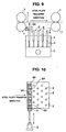
- FIG. 9 schematically shows an example of induced laminar flow nozzles used in the apparatus for cooling a steel plate according to the present invention.
- FIG. 10 is a cross sectional view taken along the line A-A of FIG. 9.
- FIG. 9 Shown in FIG. 9 are induced laminar flow nozzles 6 situated in a cooling zone allocated by a set of transfer rollers 7. In an actual line, a plurality of such cooling zones are provided, wherein a plurality of induced laminar flow nozzles 6 are located along the width direction and the transfer direction of the steel plate 1.
- a shield plate 8 is provided that is horizontally movable by a moving means 9 in the direction perpendicular to the transfer direction of the steel plate and that has a plurality of openings 8A at a predetermined pitch.
- the shield plate 8 is horizontally moved, and as a result, a part of cooling water injected to the lower surface of the steel plate 1 from the induced laminar flow nozzles 6A is blocked. Thereby, the top portion of the steel plate is prevented from being super cooled.
- each of the induced laminar flow nozzles 6A be closed to reduce the volume of the cooling water to about 1/2 of the normal volume of the cooling water.
- the shield plate 8 is positioned where the openings of the induced laminar flow nozzles 6A are each fully opened. However, when the top portion of the steel plate is detected by sensors (not shown) located between sets of transfer rollers 7, the shield plate 8 horizontally moves to close the half of the opening of each of the induced laminar flow nozzles 6A. After the top portion of the steel plate passes over the induced laminar flow nozzles 6A, the shield plate 8 is horizontally moved to fully open the openings of the individual induced laminar flow nozzles 6A. Thereby, cooling capabilities for the upper and lower surfaces of the steel plate are equalized.
- the top portion of the steel plate can be prevented substantially completely from being super cooled.
- These operations should only be conducted until uniform temperature distribution is attained on the upper and lower surfaces of the steel plate; that is, the operations need not be performed in all the cooling zones.
- the present invention is effective to dispose a rectifying means on an entrant side of the cooling zone located on the side of highest upstream, whereby the steel plate is rectified and then cooled.
- the rectifying means is used to rectify hot steel plates having a thickness of 50 mm or less, so that it may be of the type having a simple construction as compared with an ordinary hot rectifying machine.
- any one of the examples exhibited a very small amount of distortion in the width direction and in the top portion, regardless of the length of steel plate and the cooling termination temperature. As such, rectification was not required in the subsequent process.
Landscapes
- Chemical & Material Sciences (AREA)
- Engineering & Computer Science (AREA)
- Mechanical Engineering (AREA)
- Physics & Mathematics (AREA)
- Thermal Sciences (AREA)
- Crystallography & Structural Chemistry (AREA)
- Materials Engineering (AREA)
- Metallurgy (AREA)
- Organic Chemistry (AREA)
- Heat Treatment Of Strip Materials And Filament Materials (AREA)
- Heat Treatments In General, Especially Conveying And Cooling (AREA)
Abstract
Description
| Testing | Method | Shielding conditions | Length of steel plate (m) | Cooling termination temperature (°C) | Width distortion (mm) | Top portion distortion (mm) |
| Example 1 | FIG. 3 | Top portion only | 12 | 500 | 3 | 2 |
| Example 2 | FIG. 3 | Top portion only | 36 | 500 | 5 | 2 |
| Example 3 | FIG. 3 | Top portion only | 36 | | 4 | 3 |
| Comparative example 1 | FIG. 3 | None | 12 | 500 | 5 | 45 |
| Comparative example 2 | FIG. 4 | Top portion only | 12 | 500 | 60 | 20 |
| Comparative example 3 | FIG. 4 | None | 12 | 500 | 80 | 50 |
| Comparative example 4 | FIG. 5 | Top portion only | 12 | 500 | 50 | 45 |
| Comparative example 5 | FIG. 5 | None | 12 | 500 | 65 | 50 |
Claims (9)
- A method for cooling a steel plate comprising the steps of:wherein when a top portion of the steel plate passes over the induced laminar flow nozzles located at least on the side of highest upstream, a volume of the cooling water to be injected from each of the induced laminar flow nozzles is reduced.forming a water pool with jets of cooling water being injected to impinge on one another by using one slit nozzle and a plurality of induced laminar flow nozzles, the slit nozzle being provided in a position on an upper surface side of the steel plate, and the induced laminar flow nozzles being provided in a position on a lower surface side of the steel plate along a transfer direction and a direction perpendicular to the transfer direction; andpassing the steel plate into the water pool,
- A method for cooling a steel plate, wherein the method of claim 1 is repeatedly carried out a plurality of times.
- The method according to claim 2, further comprising the step of air cooling the steel plate at least two times while the method of claim 1 is repeatedly carried out a plurality of times.
- The method according to claim 2, wherein when the top portion of the steel plate passes at least over induced laminar flow nozzles located on the side of highest upstream, also the volume of the cooling water to be injected from the slit nozzle is reduced.
- The method according to claim 2, further comprising the step of rectifying the steel plate prior to cooling the steel plate.
- An apparatus for cooling a steel plate comprising:wherein a plurality of cooling zones are provided for cooling the steel plate by forming a water pool with cooling water being injected from the slit nozzle and the induced laminar flow nozzles, and a cooling water control means is provided in the cooling zone located on the side of highest upstream among the plurality of cooling zones to control the volume of the cooling water to be injected from each of the induced laminar flow nozzles located at least on the side of highest upstream.one slit nozzle provided in a position on an upper surface side of the steel plate; anda plurality of induced laminar flow nozzles provided in a position on a lower surface side of the steel plate along a transfer direction and a direction perpendicular to the transfer direction;
- The apparatus according to claim 5, wherein the cooling water control means is a shield plate.
- The apparatus according to claim 5, further comprising a flow regulating valve provided for each of the cooling zones to regulate the volume of the cooling water to be injected from the slit nozzle and each of the induced laminar flow nozzles.
- The apparatus according to claim 6, further comprising a rectifying means provided on an entrant side of the cooling zone located on the side of highest upstream for rectifying the steel plate.
Applications Claiming Priority (3)
| Application Number | Priority Date | Filing Date | Title |
|---|---|---|---|
| JP2001290004A JP4678112B2 (en) | 2001-09-21 | 2001-09-21 | Steel plate cooling method and apparatus |
| JP2001290004 | 2001-09-21 | ||
| PCT/JP2002/009252 WO2003026813A1 (en) | 2001-09-21 | 2002-09-11 | Method and device for cooling steel sheet |
Publications (3)
| Publication Number | Publication Date |
|---|---|
| EP1428589A1 true EP1428589A1 (en) | 2004-06-16 |
| EP1428589A4 EP1428589A4 (en) | 2005-08-10 |
| EP1428589B1 EP1428589B1 (en) | 2007-12-19 |
Family
ID=19112404
Family Applications (1)
| Application Number | Title | Priority Date | Filing Date |
|---|---|---|---|
| EP02767944A Expired - Lifetime EP1428589B1 (en) | 2001-09-21 | 2002-09-11 | Method and device for cooling steel sheet |
Country Status (8)
| Country | Link |
|---|---|
| US (1) | US7294215B2 (en) |
| EP (1) | EP1428589B1 (en) |
| JP (1) | JP4678112B2 (en) |
| KR (1) | KR100580357B1 (en) |
| CN (1) | CN1556733A (en) |
| DE (1) | DE60224211T2 (en) |
| TW (1) | TWI222902B (en) |
| WO (1) | WO2003026813A1 (en) |
Cited By (3)
| Publication number | Priority date | Publication date | Assignee | Title |
|---|---|---|---|---|
| WO2015075041A1 (en) | 2013-11-25 | 2015-05-28 | Loi Thermprocess Gmbh | Method for heat-treating, and quenching device for cooling plate- or web-like sheet metal |
| EP2910653A1 (en) * | 2014-02-22 | 2015-08-26 | Josef Stutz | Method and device for cooling metal strips |
| WO2017115110A1 (en) | 2015-12-30 | 2017-07-06 | Arcelormittal | Process and device for cooling a metal substrate |
Families Citing this family (13)
| Publication number | Priority date | Publication date | Assignee | Title |
|---|---|---|---|---|
| BE1014868A3 (en) * | 2002-06-06 | 2004-05-04 | Four Industriel Belge | METHOD AND DEVICE patenting STEEL SON |
| JP4767544B2 (en) | 2005-01-11 | 2011-09-07 | 新日本製鐵株式会社 | Steel sheet cooling control method |
| KR100973691B1 (en) * | 2005-08-30 | 2010-08-03 | 제이에프이 스틸 가부시키가이샤 | Cooling facility and cooling method of steel plate, hot rolling facility and hot rolling method of steel plate using same |
| JP4586682B2 (en) * | 2005-08-30 | 2010-11-24 | Jfeスチール株式会社 | Steel sheet hot rolling equipment and hot rolling method |
| KR101424905B1 (en) * | 2010-01-29 | 2014-08-01 | 도시바 미쓰비시덴키 산교시스템 가부시키가이샤 | Water-injection control device in rolling line, water-injection control method, water-injection control program |
| EP2792428A1 (en) * | 2013-04-15 | 2014-10-22 | Siemens VAI Metals Technologies GmbH | Cooling device with width-dependent cooling effect |
| CN103341507B (en) * | 2013-06-24 | 2015-03-11 | 中冶赛迪工程技术股份有限公司 | Device for quickly closing and adjusting ACC spraying header pipe |
| CN104162552A (en) * | 2014-06-23 | 2014-11-26 | 浙江松盛金属制品有限公司 | Cooling device for hot-rolled steel |
| US11015272B2 (en) * | 2015-03-12 | 2021-05-25 | Toray Industries, Inc | Laminated nonwoven fabric |
| JP6245766B2 (en) * | 2015-05-26 | 2017-12-13 | Primetals Technologies Japan株式会社 | Hot-rolled steel plate cooling apparatus and mask member position adjusting method |
| JP6439943B2 (en) * | 2016-03-31 | 2018-12-19 | Jfeスチール株式会社 | Steel plate bottom surface cooling method and cooling device |
| KR102180809B1 (en) * | 2018-12-17 | 2020-11-19 | 주식회사 포스코 | Apparatus for cooling metal materials |
| JP7406093B2 (en) * | 2020-03-05 | 2023-12-27 | 日本製鉄株式会社 | Cooling device and method for hot-rolled steel sheets |
Family Cites Families (14)
| Publication number | Priority date | Publication date | Assignee | Title |
|---|---|---|---|---|
| FR2517039A1 (en) * | 1981-11-26 | 1983-05-27 | Usinor | METHOD AND INSTALLATION FOR PERFORMING COOLING CONTROL OF SHEETS |
| JPS58157517A (en) * | 1982-03-11 | 1983-09-19 | Sumitomo Metal Ind Ltd | Manufacture of hot rolled steel plate having thin scale |
| JPS6043435A (en) * | 1983-08-17 | 1985-03-08 | Nippon Steel Corp | Method and device for cooling hot-rolled steel plate |
| JPS6070126A (en) | 1983-09-27 | 1985-04-20 | Nippon Kokan Kk <Nkk> | Apparatus for cooling underside of metallic plate |
| JPS61229414A (en) * | 1985-04-03 | 1986-10-13 | Mitsubishi Heavy Ind Ltd | Slit lamina cooling device for hot rolled steel sheet |
| JPS6221413A (en) | 1985-07-19 | 1987-01-29 | Sumitomo Metal Ind Ltd | Cooling method and device for steel plate |
| JPH078373B2 (en) * | 1986-12-29 | 1995-02-01 | 石川島播磨重工業株式会社 | Metal plate cooling system |
| JPH01317615A (en) * | 1988-03-30 | 1989-12-22 | Sumitomo Metal Ind Ltd | Spray header |
| JPH0773736B2 (en) * | 1988-12-28 | 1995-08-09 | 新日本製鐵株式会社 | Cooling control device for hot rolled steel sheet |
| JP3287245B2 (en) | 1996-12-10 | 2002-06-04 | 日本鋼管株式会社 | Apparatus and method for cooling hot steel sheet |
| JPH10291019A (en) * | 1997-04-17 | 1998-11-04 | Nkk Corp | Cooling method for hot steel sheet and cooling device for hot steel sheet |
| JP3173574B2 (en) * | 1997-05-16 | 2001-06-04 | 日本鋼管株式会社 | High temperature steel plate cooling system |
| JPH11347629A (en) * | 1998-06-09 | 1999-12-21 | Nkk Corp | High-temperature steel sheet straightening and cooling apparatus and straightening and cooling method |
| JP2000001719A (en) * | 1998-06-16 | 2000-01-07 | Nkk Corp | High temperature steel plate cooling system |
-
2001
- 2001-09-21 JP JP2001290004A patent/JP4678112B2/en not_active Expired - Fee Related
-
2002
- 2002-09-11 EP EP02767944A patent/EP1428589B1/en not_active Expired - Lifetime
- 2002-09-11 DE DE60224211T patent/DE60224211T2/en not_active Expired - Lifetime
- 2002-09-11 US US10/489,382 patent/US7294215B2/en not_active Expired - Lifetime
- 2002-09-11 WO PCT/JP2002/009252 patent/WO2003026813A1/en not_active Ceased
- 2002-09-11 KR KR1020047003863A patent/KR100580357B1/en not_active Expired - Lifetime
- 2002-09-11 CN CNA028184572A patent/CN1556733A/en active Pending
- 2002-09-19 TW TW091121436A patent/TWI222902B/en not_active IP Right Cessation
Cited By (5)
| Publication number | Priority date | Publication date | Assignee | Title |
|---|---|---|---|---|
| WO2015075041A1 (en) | 2013-11-25 | 2015-05-28 | Loi Thermprocess Gmbh | Method for heat-treating, and quenching device for cooling plate- or web-like sheet metal |
| DE102013019619A1 (en) | 2013-11-25 | 2015-05-28 | Loi Thermprocess Gmbh | Method for heat treatment and quenching device for cooling plate-shaped or sheet metal sheet metal |
| EP2910653A1 (en) * | 2014-02-22 | 2015-08-26 | Josef Stutz | Method and device for cooling metal strips |
| WO2017115110A1 (en) | 2015-12-30 | 2017-07-06 | Arcelormittal | Process and device for cooling a metal substrate |
| US11072839B2 (en) | 2015-12-30 | 2021-07-27 | Arcelormittal | Process and device for cooling a metal substrate |
Also Published As
| Publication number | Publication date |
|---|---|
| KR100580357B1 (en) | 2006-05-16 |
| DE60224211D1 (en) | 2008-01-31 |
| JP2003094106A (en) | 2003-04-02 |
| CN1556733A (en) | 2004-12-22 |
| TWI222902B (en) | 2004-11-01 |
| JP4678112B2 (en) | 2011-04-27 |
| US20040244886A1 (en) | 2004-12-09 |
| EP1428589A4 (en) | 2005-08-10 |
| EP1428589B1 (en) | 2007-12-19 |
| DE60224211T2 (en) | 2008-12-04 |
| KR20040029180A (en) | 2004-04-03 |
| WO2003026813A1 (en) | 2003-04-03 |
| US7294215B2 (en) | 2007-11-13 |
Similar Documents
| Publication | Publication Date | Title |
|---|---|---|
| US7294215B2 (en) | Method and device for cooling steel sheet | |
| CN100404154C (en) | Accelerated controlled cooling process for steel plates, steel plates produced by it, and cooling equipment | |
| EP1935522B1 (en) | Reversing rolling mill with cooling facility and corresponding method of cooling a steel plate or sheet | |
| EP2495343B1 (en) | Gas jet cooling device for continuous annealing furnace | |
| US20110209515A1 (en) | Method and device for cooling a leader or band of a metal strand in a hot-rolling mill | |
| JP5928412B2 (en) | Steel plate vertical cooling device and method for producing hot dip galvanized steel plate using the same | |
| JP5685861B2 (en) | Draining device, draining method and cooling equipment for hot steel plate | |
| JP6079522B2 (en) | Steel plate cooling device and steel plate cooling method | |
| JP2898873B2 (en) | Lower surface cooling device for high temperature metal plate | |
| JP4337157B2 (en) | Steel plate cooling method and apparatus | |
| JP2000001719A (en) | High temperature steel plate cooling system | |
| JP3739934B2 (en) | Uniform cooling method for thin steel sheet | |
| JP6439943B2 (en) | Steel plate bottom surface cooling method and cooling device | |
| DE69806136T2 (en) | DEVICE AND METHOD FOR COOLING ROLLING WIRE | |
| US5186885A (en) | Apparatus for cooling a traveling strip | |
| JP3277985B2 (en) | High temperature steel plate cooling system | |
| KR101988751B1 (en) | Cooling apparatus for steel sheet | |
| JP2698305B2 (en) | Cooling method of steel plate | |
| JP3327223B2 (en) | Method and apparatus for cooling U-shaped sheet pile | |
| JP2551663Y2 (en) | Cooling equipment for hot rolled steel sheets | |
| JP4682669B2 (en) | H-shaped steel cooling equipment and cooling method | |
| JPS61135423A (en) | Hot straightening device of two layered clad metal plate | |
| KR20030016433A (en) | A Method for Hot rolled Steel Sheets Having Clean Surface | |
| JP3265966B2 (en) | Method and apparatus for cooling section steel | |
| JP2003034818A (en) | Metal strip cooling method |
Legal Events
| Date | Code | Title | Description |
|---|---|---|---|
| PUAI | Public reference made under article 153(3) epc to a published international application that has entered the european phase |
Free format text: ORIGINAL CODE: 0009012 |
|
| 17P | Request for examination filed |
Effective date: 20040318 |
|
| AK | Designated contracting states |
Kind code of ref document: A1 Designated state(s): AT BE BG CH CY CZ DE DK EE ES FI FR GB GR IE IT LI LU MC NL PT SE SK TR |
|
| AX | Request for extension of the european patent |
Extension state: AL LT LV MK RO SI |
|
| RIN1 | Information on inventor provided before grant (corrected) |
Inventor name: OMATA, KAZUO,C/O INTEL. PROP. DEP. Inventor name: TSUYAMA, SEISHI,C/O INTEL. PROP. DEP. Inventor name: TAKAHASHI, ISAO,C/O INTEL. PROP. DEP. Inventor name: FUJIBAYASHI, AKIO,C/O INTEL. PROP. DEP. Inventor name: TAGANE, AKIRA,C/O INTEL. PROP. DEP. |
|
| A4 | Supplementary search report drawn up and despatched |
Effective date: 20050624 |
|
| RIC1 | Information provided on ipc code assigned before grant |
Ipc: 7C 21D 9/46 B Ipc: 7B 21B 45/02 A |
|
| 17Q | First examination report despatched |
Effective date: 20060202 |
|
| GRAP | Despatch of communication of intention to grant a patent |
Free format text: ORIGINAL CODE: EPIDOSNIGR1 |
|
| RBV | Designated contracting states (corrected) |
Designated state(s): DE FR GB IT |
|
| GRAS | Grant fee paid |
Free format text: ORIGINAL CODE: EPIDOSNIGR3 |
|
| GRAA | (expected) grant |
Free format text: ORIGINAL CODE: 0009210 |
|
| AK | Designated contracting states |
Kind code of ref document: B1 Designated state(s): DE FR GB IT |
|
| REG | Reference to a national code |
Ref country code: GB Ref legal event code: FG4D |
|
| REF | Corresponds to: |
Ref document number: 60224211 Country of ref document: DE Date of ref document: 20080131 Kind code of ref document: P |
|
| ET | Fr: translation filed | ||
| PLBE | No opposition filed within time limit |
Free format text: ORIGINAL CODE: 0009261 |
|
| STAA | Information on the status of an ep patent application or granted ep patent |
Free format text: STATUS: NO OPPOSITION FILED WITHIN TIME LIMIT |
|
| 26N | No opposition filed |
Effective date: 20080922 |
|
| REG | Reference to a national code |
Ref country code: FR Ref legal event code: PLFP Year of fee payment: 14 |
|
| REG | Reference to a national code |
Ref country code: FR Ref legal event code: PLFP Year of fee payment: 15 |
|
| REG | Reference to a national code |
Ref country code: FR Ref legal event code: PLFP Year of fee payment: 16 |
|
| REG | Reference to a national code |
Ref country code: FR Ref legal event code: PLFP Year of fee payment: 17 |
|
| PGFP | Annual fee paid to national office [announced via postgrant information from national office to epo] |
Ref country code: IT Payment date: 20210811 Year of fee payment: 20 Ref country code: FR Payment date: 20210812 Year of fee payment: 20 |
|
| PGFP | Annual fee paid to national office [announced via postgrant information from national office to epo] |
Ref country code: GB Payment date: 20210805 Year of fee payment: 20 Ref country code: DE Payment date: 20210803 Year of fee payment: 20 |
|
| REG | Reference to a national code |
Ref country code: DE Ref legal event code: R071 Ref document number: 60224211 Country of ref document: DE |
|
| REG | Reference to a national code |
Ref country code: GB Ref legal event code: PE20 Expiry date: 20220910 |
|
| PG25 | Lapsed in a contracting state [announced via postgrant information from national office to epo] |
Ref country code: GB Free format text: LAPSE BECAUSE OF EXPIRATION OF PROTECTION Effective date: 20220910 |