EP1428580A1 - Foam or mist dispenser - Google Patents
Foam or mist dispenser Download PDFInfo
- Publication number
- EP1428580A1 EP1428580A1 EP02080188A EP02080188A EP1428580A1 EP 1428580 A1 EP1428580 A1 EP 1428580A1 EP 02080188 A EP02080188 A EP 02080188A EP 02080188 A EP02080188 A EP 02080188A EP 1428580 A1 EP1428580 A1 EP 1428580A1
- Authority
- EP
- European Patent Office
- Prior art keywords
- liquid
- container
- dispenser according
- foam
- dispenser
- Prior art date
- Legal status (The legal status is an assumption and is not a legal conclusion. Google has not performed a legal analysis and makes no representation as to the accuracy of the status listed.)
- Withdrawn
Links
- 239000006260 foam Substances 0.000 title claims abstract description 36
- 239000003595 mist Substances 0.000 title claims abstract description 15
- 239000007788 liquid Substances 0.000 claims abstract description 62
- 238000004140 cleaning Methods 0.000 claims description 8
- 238000005086 pumping Methods 0.000 claims description 3
- 239000007787 solid Substances 0.000 claims description 3
- 238000005187 foaming Methods 0.000 claims description 2
- 239000004094 surface-active agent Substances 0.000 claims description 2
- 239000000203 mixture Substances 0.000 description 4
- 239000007921 spray Substances 0.000 description 3
- 230000015572 biosynthetic process Effects 0.000 description 2
- 230000008878 coupling Effects 0.000 description 2
- 238000010168 coupling process Methods 0.000 description 2
- 238000005859 coupling reaction Methods 0.000 description 2
- 239000002781 deodorant agent Substances 0.000 description 2
- 239000000463 material Substances 0.000 description 2
- 238000011084 recovery Methods 0.000 description 2
- 230000001588 bifunctional effect Effects 0.000 description 1
- 239000006071 cream Substances 0.000 description 1
- 230000007717 exclusion Effects 0.000 description 1
- 229920002457 flexible plastic Polymers 0.000 description 1
- 230000001788 irregular Effects 0.000 description 1
- 230000007246 mechanism Effects 0.000 description 1
- 239000008267 milk Substances 0.000 description 1
- 210000004080 milk Anatomy 0.000 description 1
- 235000013336 milk Nutrition 0.000 description 1
- 239000003973 paint Substances 0.000 description 1
- 239000002245 particle Substances 0.000 description 1
- 239000013618 particulate matter Substances 0.000 description 1
- 239000011148 porous material Substances 0.000 description 1
- 239000008262 pumice Substances 0.000 description 1
- 239000004575 stone Substances 0.000 description 1
- 239000000725 suspension Substances 0.000 description 1
Images


Classifications
-
- B—PERFORMING OPERATIONS; TRANSPORTING
- B65—CONVEYING; PACKING; STORING; HANDLING THIN OR FILAMENTARY MATERIAL
- B65D—CONTAINERS FOR STORAGE OR TRANSPORT OF ARTICLES OR MATERIALS, e.g. BAGS, BARRELS, BOTTLES, BOXES, CANS, CARTONS, CRATES, DRUMS, JARS, TANKS, HOPPERS, FORWARDING CONTAINERS; ACCESSORIES, CLOSURES, OR FITTINGS THEREFOR; PACKAGING ELEMENTS; PACKAGES
- B65D83/00—Containers or packages with special means for dispensing contents
- B65D83/14—Containers for dispensing liquid or semi-liquid contents by internal gaseous pressure, i.e. aerosol containers comprising propellant
- B65D83/28—Nozzles, nozzle fittings or accessories specially adapted therefor
-
- B—PERFORMING OPERATIONS; TRANSPORTING
- B05—SPRAYING OR ATOMISING IN GENERAL; APPLYING FLUENT MATERIALS TO SURFACES, IN GENERAL
- B05B—SPRAYING APPARATUS; ATOMISING APPARATUS; NOZZLES
- B05B7/00—Spraying apparatus for discharge of liquids or other fluent materials from two or more sources, e.g. of liquid and air, of powder and gas
- B05B7/0018—Spraying apparatus for discharge of liquids or other fluent materials from two or more sources, e.g. of liquid and air, of powder and gas with devices for making foam
- B05B7/0025—Spraying apparatus for discharge of liquids or other fluent materials from two or more sources, e.g. of liquid and air, of powder and gas with devices for making foam with a compressed gas supply
- B05B7/0031—Spraying apparatus for discharge of liquids or other fluent materials from two or more sources, e.g. of liquid and air, of powder and gas with devices for making foam with a compressed gas supply with disturbing means promoting mixing, e.g. balls, crowns
- B05B7/0037—Spraying apparatus for discharge of liquids or other fluent materials from two or more sources, e.g. of liquid and air, of powder and gas with devices for making foam with a compressed gas supply with disturbing means promoting mixing, e.g. balls, crowns including sieves, porous members or the like
-
- B—PERFORMING OPERATIONS; TRANSPORTING
- B05—SPRAYING OR ATOMISING IN GENERAL; APPLYING FLUENT MATERIALS TO SURFACES, IN GENERAL
- B05B—SPRAYING APPARATUS; ATOMISING APPARATUS; NOZZLES
- B05B7/00—Spraying apparatus for discharge of liquids or other fluent materials from two or more sources, e.g. of liquid and air, of powder and gas
- B05B7/0018—Spraying apparatus for discharge of liquids or other fluent materials from two or more sources, e.g. of liquid and air, of powder and gas with devices for making foam
- B05B7/0025—Spraying apparatus for discharge of liquids or other fluent materials from two or more sources, e.g. of liquid and air, of powder and gas with devices for making foam with a compressed gas supply
- B05B7/0031—Spraying apparatus for discharge of liquids or other fluent materials from two or more sources, e.g. of liquid and air, of powder and gas with devices for making foam with a compressed gas supply with disturbing means promoting mixing, e.g. balls, crowns
- B05B7/0043—Spraying apparatus for discharge of liquids or other fluent materials from two or more sources, e.g. of liquid and air, of powder and gas with devices for making foam with a compressed gas supply with disturbing means promoting mixing, e.g. balls, crowns including a plurality of individual elements, e.g. needles, baffles, rotatable blades
-
- B—PERFORMING OPERATIONS; TRANSPORTING
- B05—SPRAYING OR ATOMISING IN GENERAL; APPLYING FLUENT MATERIALS TO SURFACES, IN GENERAL
- B05B—SPRAYING APPARATUS; ATOMISING APPARATUS; NOZZLES
- B05B11/00—Single-unit hand-held apparatus in which flow of contents is produced by the muscular force of the operator at the moment of use
- B05B11/01—Single-unit hand-held apparatus in which flow of contents is produced by the muscular force of the operator at the moment of use characterised by the means producing the flow
- B05B11/04—Deformable containers producing the flow, e.g. squeeze bottles
- B05B11/042—Deformable containers producing the flow, e.g. squeeze bottles the spray being effected by a gas or vapour flow in the nozzle, spray head, outlet or dip tube
- B05B11/043—Deformable containers producing the flow, e.g. squeeze bottles the spray being effected by a gas or vapour flow in the nozzle, spray head, outlet or dip tube designed for spraying a liquid
Definitions
- the present invention concerns foam or mist dispensers. It particularly concerns portable dispensers which dispense, under pressure, foam or mist from a mixture of gas and liquid and which contain a turbulence element to cause turbulence in the liquid to be dispensed.
- portable refers to hand-held dispensers, preferentially dispensers that can be held with only one hand, such as well-known existing commercial dispensers for deodorants shaving-foam, or liquid cleaning compositions.
- the improvement is also suitable for large portable dispensers, that cannot be held with only one hand but these are generally seldom used by the ordinary consumer.
- Foam or mist dispensers to dispense a mixture of liquid and gas as a foam are known to those skilled in the art.
- they comprise a container and a dispensing cap, said cap comprising a dispensing opening which, at least during dispensing, is in open connection with the upper end of a flow pipe (known as dip tube), of which the opposite end is located near the bottom of the container.
- a flow pipe known as dip tube
- Liquid and gas are being pushed out of the dispensing opening together due to the pressure difference between the inside and outside of the container.
- the pressurised gas in the containers is air but it may be another suitable gas.
- the overpressure in the container is permanent in pressurised containers.
- the overpressure can be created manually and temporarily with a pump system known in the art to pump air in the container.
- Some pump systems are able to create enough overpressure to last for a multitude of dispensing operations.
- Other pump systems e.g. those forming part of various pump dispensing heads or caps create the overpressure as part of the dispensing operation. Examples of such dispensing systems are trigger spray heads.
- Dispensers of this and similar kind are disclosed in U.S. Patents Nos. 6,053,364, 5,271,530, 5,443,569, etc.
- foam or mist dispensers are sold with a solution inside the container and a flat mesh or net in the flow path of the liquid to form the foam or mist.
- foam forming elements are often not very efficient for creating a desired thick foam.
- the present invention seeks to solve this problem by installing a 3-D turbulence element in the flow path of the liquid i.e. somewhere in the dip tube that conveys the liquid from the bottom of a container towards the container cap or above the dip tube in the container cap.
- the invention is particularly suitable for dispensers comprising a means for manually temporarily pressurising the container, such as with a manually operated pump system of by squeezing the walls.
- the invention provides a portable dispenser for foam or mist comprising a container for a liquid which is or can be pressurised, a cap closing the container, and a dip tube having two ends, the first end co-operating with an opening in the cap through which the liquid mist or foam is expelled from the container and the second opposite end being close to the bottom of said container, the dispenser being provided with a three-dimensional turbulence element which is mounted in the flow path of the liquid before it leaves the dispensing opening in the cap.
- a turbulence element is mounted in the liquid flow path such that the gas and the liquid flowing to the dispensing opening meet just before or while they pass that turbulence element.
- Other additional turbulence elements may be mounted in other parts of liquid flow path.
- Turbulence elements of the present invention may mounted movably in the liquid flow path and may act in a bifunctional way as a turbulence generator as well as a valve.
- the dip tube can be provided with one or more upper ends and/or one or more lower ends, meaning that said pipe can be branched or split thus providing additional ends, so that at least one upper end and one lower end are provided with at least one turbulence element.
- the liquid preferably occupies less than 95% of the total volume inside the container of the dispenser, more preferably less than 90%.
- the dispenser comprises a mixing chamber in the liquid flow path, preferably close to the dispensing opening in the cap and down-stream from the opening connecting the liquid flow path to the headspace in the container.
- opening may be in the mixing chamber such that gas (air) and liquid meet in the mixing chamber.
- the turbulence element may be mounted in the mixing chamber or be part of the mixing chamber.
- a three-dimensional turbulence element is any and all three-dimensional structure capable of provoking turbulence of the liquid while flowing to the dispensing opening of the dispenser.
- 3-D turbulence elements can be sets of lashes or bristles inside the dip tube or mixing chamber, or next to the ends thereof, as well as parallel or random sets of fins, parallel or randomly arranged apertured or non-apertured flat disks of same or different diameters, a distribution of filaments either loose or as a woven or nonwoven web or plug, shaped particles like spheres, cylinders, other mixed and irregular shapes, porous elements such as pumice stone or natural or artificial polymeric foam, etc.
- Combinations of two or more turbulence elements are also suitable.
- a turbulence element at the liquid output end is particularly suitable to the formation of foam, which can be turned into mist depending on the geometry of the output orifice and the pressure used, as is known by those skilled in the art.
- the 3-D turbulence element located in a mixing chamber at the upper end of the dip tube, is a rotatable shaft (either idle of mechanically driven) with propeller blades, where air and the liquid are mixed to obtain foam.
- example B denotes concentric propeller blades
- example C denotes shovel-type blades
- example D denotes eccentric blades.
- Such blades may be used alone or in combination.
- the arrows in fig. 1 show that the shaft can turn either clockwise or counter clockwise.
- a means to increase the inner pressure in the container of the dispenser of the invention can be any of those known in the art, more particularly comprising (a) (partially) flexible walls so that the user's hand can compress same or (b) a pumping device actuated by the user's hands or finger(s), mainly for containers having rigid walls.
- the mechanisms of hand-actuated pumps, including combined air and liquid pumps, are known to one skilled in the art, and do not impose any limitation to the scope of the present invention
- the container of the dispenser of this invention can have any shape suitable to portability and handling, without excluding any shape.
- the cap of the dispenser of the invention can be of any shape, aimed at the function of closing the container after it has been filled with the liquid and allowing same to be dispensed.
- a cap having an orifice and a coupling for the upper end of the dip tube are particularly suitable.
- the cap can house a pumping device to be actuated by the user's fingers, for instance also comprising a coupling for the upper end of the dip tube and/or a mixing chamber.
- the dispenser parts may be made of any material suitable for the purpose. A majority, if not all, of the parts are suitably made from polymeric material.
- the dispensers according to the invention may be used for any liquid intended to be dispensed as a foam or mist examples are: edible liquids such as cream or milk, paint or cleaning liquids. They are particularly suitable for dispensing cleaning liquids as a foam. Such cleaning liquids generally contain a foaming surfactant, preferably in completely dissolved form. They may also contain other components known in the art as components of cleaning liquids. They may even contain solid particulate matter provided it is in stable suspension in the liquid. Preferred, however, are cleaning liquids that do not contain any undissolved solid matter.
- Figures 2-4 and 5-7 represent examples of turbulence elements in a housing suitable for mounting close to the dispensing opening of the dispenser i.e. associated with the upper end of the dip tube.
- Figures 2-4 represent a 3-D turbulence element, movably housed in a turbulence chamber, whereas figures 5-7 7 represent a fixed 3-D turbulence element. In both cases the use of addition turbulence elements elsewhere in the dip tube is optional.
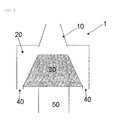
- Figs. 2, 3 and 4 refer to part of a dispenser 1, having a foam outlet 10, a turbulence chamber 20, a 3-D turbulence element 30, air input ports 40, and a dip tube 50, the lower end of it is a liquid input port.
- the container and its walls are not shown.
- Fig. 2 shows the dispenser at rest.
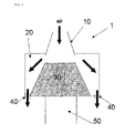
- Fig. 3 shows the dispenser when both the liquid and the air within the container are pressurised (pressurising means not shown).
- Air and liquid penetrate in the turbulence chamber 20 (respectively through input entrances 40 and 50), pass through the 3-D turbulence element 30, suitable made of a porous material such as a polymeric open cell foam, where they get mixed to form foam, which is then expelled through foam outlet 10.
- the turbulence element is lifted by the combined flow of air and liquid, not allowing liquid or air to escape alongside the turbulence element through outlet 10.
- Fig. 4 shows the recovery position, when air is replenished in the container after the foam is dispensed and pressure is being released.
- the turbulence element 30 returns to the rest position within the turbulence chamber 20, while air will enter the container through ports 10 and 40 (not through the 3-D turbulence elements 30).
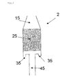
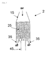
- Figures 5, 6 and 7 show part of a dispenser 2, comprising a foam outlet 15, a 3-D turbulence element 25, air inlet ports 35 and a dip tube 45. Pressurising means and the walls of the dispenser are not shown.
- Fig. 5 shows the dispenser at rest.
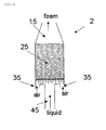
- Fig. 6 shows air being forced through ports 35, and liquid being forced up the dip tube 45, so that air and liquid are forced to be mixed inside the 3-D turbulence element 25, with the formation of foam that is dispensed through foam outlet 15.
- Fig. 7 shows the recovery situation, when air is replenished in the container after the foam is dispensed. Air comes through foam outlet 15, through the 3-D turbulence element 25 and into the container through ports 35.
Landscapes
- Chemical & Material Sciences (AREA)
- Dispersion Chemistry (AREA)
- Engineering & Computer Science (AREA)
- Mechanical Engineering (AREA)
- Containers And Packaging Bodies Having A Special Means To Remove Contents (AREA)
Abstract
Portable dispenser (1) for foam or mist comprising a container for a
liquid which is or can be pressurised, a cap closing the container, and
a dip tube (50) of which the upper end cooperates with an opening in the
cap through which the liquid mist or foam is expelled from the container
and the lower end is close to the bottom of the container. The dispenser
(1) is provided with a three-dimensional turbulence element (35) that is
mounted in the flow path of the liquid before it leaves the dispensing
opening in the cap.
Description
- The present invention concerns foam or mist dispensers. It particularly concerns portable dispensers which dispense, under pressure, foam or mist from a mixture of gas and liquid and which contain a turbulence element to cause turbulence in the liquid to be dispensed.
- The term "portable" as used herein refers to hand-held dispensers, preferentially dispensers that can be held with only one hand, such as well-known existing commercial dispensers for deodorants shaving-foam, or liquid cleaning compositions. The improvement is also suitable for large portable dispensers, that cannot be held with only one hand but these are generally seldom used by the ordinary consumer.
- Foam or mist dispensers to dispense a mixture of liquid and gas as a foam are known to those skilled in the art. As a common characteristic, they comprise a container and a dispensing cap, said cap comprising a dispensing opening which, at least during dispensing, is in open connection with the upper end of a flow pipe (known as dip tube), of which the opposite end is located near the bottom of the container. Liquid and gas are being pushed out of the dispensing opening together due to the pressure difference between the inside and outside of the container. Conveniently the pressurised gas in the containers is air but it may be another suitable gas. The overpressure in the container is permanent in pressurised containers. For non-pressurised containers the overpressure can be created manually and temporarily with a pump system known in the art to pump air in the container. Some pump systems are able to create enough overpressure to last for a multitude of dispensing operations. Other pump systems e.g. those forming part of various pump dispensing heads or caps create the overpressure as part of the dispensing operation. Examples of such dispensing systems are trigger spray heads. Dispensers of this and similar kind are disclosed in U.S. Patents Nos. 6,053,364, 5,271,530, 5,443,569, etc
- In alternative and simple to operate dispensing systems the overpressure is simply created by manual squeezing of the container which to this end has flexible walls. Such containers are known as 'squeeze bottles', often used for dispensing a deodorant mist (or spray). They are flexible plastic containers filled with liquid, and the dispensing takes place when the user's hand compresses the flexible walls of the container, deforming them and increasing the pressure in the head space, compelling the liquid to go upward through the dip tube, and be ejected from the container. Due to the configuration of the cap dispensing orifice and/or the use of two-dimensional structures like a foam or mist-forming mesh, the liquid can be expelled as a foam or spray. An exemplary embodiment of such dispenser is shown in U.S. patent 2,642,313, published in 1953.
- Known foam or mist dispensers are sold with a solution inside the container and a flat mesh or net in the flow path of the liquid to form the foam or mist. Such foam forming elements are often not very efficient for creating a desired thick foam.
- The present invention seeks to solve this problem by installing a 3-D turbulence element in the flow path of the liquid i.e. somewhere in the dip tube that conveys the liquid from the bottom of a container towards the container cap or above the dip tube in the container cap. The invention is particularly suitable for dispensers comprising a means for manually temporarily pressurising the container, such as with a manually operated pump system of by squeezing the walls.
- Thus, the invention provides a portable dispenser for foam or mist comprising a container for a liquid which is or can be pressurised, a cap closing the container, and a dip tube having two ends, the first end co-operating with an opening in the cap through which the liquid mist or foam is expelled from the container and the second opposite end being close to the bottom of said container, the dispenser being provided with a three-dimensional turbulence element which is mounted in the flow path of the liquid before it leaves the dispensing opening in the cap.
- In a preferred embodiment of the invention there are one or more openings in the upper part of the dip tube or in the cap which connect the headspace above the liquid in the container with the liquid flow path. Thus, under pressure a mixture of liquid and pressurised gas (preferably air) is expelled from the dispenser as foam. In a more preferred embodiment a turbulence element is mounted in the liquid flow path such that the gas and the liquid flowing to the dispensing opening meet just before or while they pass that turbulence element. Other additional turbulence elements may be mounted in other parts of liquid flow path.
- Turbulence elements of the present invention may mounted movably in the liquid flow path and may act in a bifunctional way as a turbulence generator as well as a valve.
- In an alternative embodiment of the invention, the dip tube can be provided with one or more upper ends and/or one or more lower ends, meaning that said pipe can be branched or split thus providing additional ends, so that at least one upper end and one lower end are provided with at least one turbulence element.
- In order to provide for enough gas inside the container to obtain a satisfactory foam, the liquid preferably occupies less than 95% of the total volume inside the container of the dispenser, more preferably less than 90%.
- In some embodiments of the invention the dispenser comprises a mixing chamber in the liquid flow path, preferably close to the dispensing opening in the cap and down-stream from the opening connecting the liquid flow path to the headspace in the container. Alternatively that opening may be in the mixing chamber such that gas (air) and liquid meet in the mixing chamber. In more preferred examples of these embodiments the turbulence element may be mounted in the mixing chamber or be part of the mixing chamber.
- As used here, a three-dimensional turbulence element is any and all three-dimensional structure capable of provoking turbulence of the liquid while flowing to the dispensing opening of the dispenser. As examples of such structures, without the exclusion of any other, 3-D turbulence elements can be sets of lashes or bristles inside the dip tube or mixing chamber, or next to the ends thereof, as well as parallel or random sets of fins, parallel or randomly arranged apertured or non-apertured flat disks of same or different diameters, a distribution of filaments either loose or as a woven or nonwoven web or plug, shaped particles like spheres, cylinders, other mixed and irregular shapes, porous elements such as pumice stone or natural or artificial polymeric foam, etc.
- Combinations of two or more turbulence elements are also suitable.
- The presence of a turbulence element at the liquid output end is particularly suitable to the formation of foam, which can be turned into mist depending on the geometry of the output orifice and the pressure used, as is known by those skilled in the art. In a particular embodiment of this invention the 3-D turbulence element, located in a mixing chamber at the upper end of the dip tube, is a rotatable shaft (either idle of mechanically driven) with propeller blades, where air and the liquid are mixed to obtain foam. In the annex fig. 1 several examples of blades co-operating with such a rotatable shaft A can be seen: example B denotes concentric propeller blades, example C denotes shovel-type blades, example D denotes eccentric blades. Such blades may be used alone or in combination. The arrows in fig. 1 show that the shaft can turn either clockwise or counter clockwise.
- A means to increase the inner pressure in the container of the dispenser of the invention can be any of those known in the art, more particularly comprising (a) (partially) flexible walls so that the user's hand can compress same or (b) a pumping device actuated by the user's hands or finger(s), mainly for containers having rigid walls. The mechanisms of hand-actuated pumps, including combined air and liquid pumps, are known to one skilled in the art, and do not impose any limitation to the scope of the present invention
- The container of the dispenser of this invention can have any shape suitable to portability and handling, without excluding any shape.
- The cap of the dispenser of the invention can be of any shape, aimed at the function of closing the container after it has been filled with the liquid and allowing same to be dispensed. When the container used is flexible, a cap having an orifice and a coupling for the upper end of the dip tube are particularly suitable. When the container used is rigid, the cap can house a pumping device to be actuated by the user's fingers, for instance also comprising a coupling for the upper end of the dip tube and/or a mixing chamber.
- The dispenser parts may be made of any material suitable for the purpose. A majority, if not all, of the parts are suitably made from polymeric material.
- The dispensers according to the invention may be used for any liquid intended to be dispensed as a foam or mist examples are: edible liquids such as cream or milk, paint or cleaning liquids. They are particularly suitable for dispensing cleaning liquids as a foam. Such cleaning liquids generally contain a foaming surfactant, preferably in completely dissolved form. They may also contain other components known in the art as components of cleaning liquids. They may even contain solid particulate matter provided it is in stable suspension in the liquid. Preferred, however, are cleaning liquids that do not contain any undissolved solid matter.
- Two embodiments of the invention are outlined below with reference to the drawings attached hereto.
- Figures 2-4 and 5-7 represent examples of turbulence elements in a housing suitable for mounting close to the dispensing opening of the dispenser i.e. associated with the upper end of the dip tube. Figures 2-4 represent a 3-D turbulence element, movably housed in a turbulence chamber, whereas figures 5-7 7 represent a fixed 3-D turbulence element. In both cases the use of addition turbulence elements elsewhere in the dip tube is optional.
- Figs. 2, 3 and 4 refer to part of a
dispenser 1, having afoam outlet 10, aturbulence chamber 20, a 3-D turbulence element 30,air input ports 40, and adip tube 50, the lower end of it is a liquid input port. The container and its walls are not shown. - Fig. 2 shows the dispenser at rest.
- Fig. 3 shows the dispenser when both the liquid and the air within the container are pressurised (pressurising means not shown). Air and liquid penetrate in the turbulence chamber 20 (respectively through input entrances 40 and 50), pass through the 3-
D turbulence element 30, suitable made of a porous material such as a polymeric open cell foam, where they get mixed to form foam, which is then expelled throughfoam outlet 10. The turbulence element is lifted by the combined flow of air and liquid, not allowing liquid or air to escape alongside the turbulence element throughoutlet 10. - Fig. 4 shows the recovery position, when air is replenished in the container after the foam is dispensed and pressure is being released. The
turbulence element 30 returns to the rest position within theturbulence chamber 20, while air will enter the container throughports 10 and 40 (not through the 3-D turbulence elements 30). - Figures 5, 6 and 7 show part of a
dispenser 2, comprising afoam outlet 15, a 3-D turbulence element 25,air inlet ports 35 and adip tube 45. Pressurising means and the walls of the dispenser are not shown. - Fig. 5 shows the dispenser at rest.
- Fig. 6 shows air being forced through
ports 35, and liquid being forced up thedip tube 45, so that air and liquid are forced to be mixed inside the 3-D turbulence element 25, with the formation of foam that is dispensed throughfoam outlet 15. - Fig. 7 shows the recovery situation, when air is replenished in the container after the foam is dispensed. Air comes through
foam outlet 15, through the 3-D turbulence element 25 and into the container throughports 35. - It should be also noted that in the case of vertical inversion of the dispenser, the air and liquid inlets to the mixing chamber exchange function the air being sucked in via the dip tube.
- It will be clear one skilled in the art, with the aid of the text and the figures presented herein, that there are many possible alternative embodiments permitted by this invention without departing from the scope of protection provided by the following claims.
Claims (14)
- Portable dispenser for foam or mist comprising a container for a liquid which is or can be pressurised, a cap closing the container, and a dip tube having two ends, the first end co-operating with a dispensing opening in the cap through which the liquid mist or foam is expelled from the container when it is under pressure and the second opposite end being close to the bottom of said container, characterized in that the dispenser is provided with a three-dimensional turbulence element which is mounted in the flow path of the liquid before it leaves the dispensing opening in the cap
- Dispenser according to claim 1 characterized in that it comprises a means for manually pressurising the container.
- Dispenser according to claim 2 characterized in that it comprises a manually operated pumping device.
- Dispenser according to claim 2 characterized in that it has at least partially flexible walls suitable to enable the container to be pressurised by squeezing.
- Dispenser according to claims 1-5, characterized in that there are one or more openings in the upper part of the dip tube or the cap which connect the headspace above the liquid with the liquid flow path.
- Dispenser according to claim 5 characterized in that the turbulence element is mounted in the liquid flow path such that the gas and the liquid flowing to the dispensing opening meet just before or while they pass through the turbulence element.
- Dispenser according to claims 1-6 characterized in that it comprises a mixing chamber in the liquid flow path close to the dispensing opening in the cap and down-stream from, or comprising, the opening connecting the liquid flow path to the head space in the container.
- Dispenser according to claim 7 characterized in that the turbulence element is mounted in, or is part of, the mixing chamber.
- Dispenser according to claims 1-8 characterized in that the turbulence element is a porous element.
- Dispenser according to claim 9 characterised in that the porous element is made of polymeric foam.
- Dispenser according to claims 1-8 characterized in that the turbulence element is a web or plug of filaments.
- Dispenser according to claims 1-11 characterised in that it is filled to less than 95% of its volume with liquid.
- Dispenser according to claim 12 characterised in that the liquid is a cleaning liquid comprising a foaming surfactant.
- Dispenser according to claim 13 characterised in that the cleaning liquid does not contain any undissolved solids.
Priority Applications (1)
| Application Number | Priority Date | Filing Date | Title |
|---|---|---|---|
| EP02080188A EP1428580A1 (en) | 2002-12-11 | 2002-12-11 | Foam or mist dispenser |
Applications Claiming Priority (1)
| Application Number | Priority Date | Filing Date | Title |
|---|---|---|---|
| EP02080188A EP1428580A1 (en) | 2002-12-11 | 2002-12-11 | Foam or mist dispenser |
Publications (1)
| Publication Number | Publication Date |
|---|---|
| EP1428580A1 true EP1428580A1 (en) | 2004-06-16 |
Family
ID=32319649
Family Applications (1)
| Application Number | Title | Priority Date | Filing Date |
|---|---|---|---|
| EP02080188A Withdrawn EP1428580A1 (en) | 2002-12-11 | 2002-12-11 | Foam or mist dispenser |
Country Status (1)
| Country | Link |
|---|---|
| EP (1) | EP1428580A1 (en) |
Cited By (3)
| Publication number | Priority date | Publication date | Assignee | Title |
|---|---|---|---|---|
| EP2397219A3 (en) * | 2010-06-15 | 2013-06-26 | Volker Barth | Device for foaming a liquid |
| EP2903489A4 (en) * | 2012-10-04 | 2015-11-04 | Arminak & Associates Llc | MIXING CHAMBER OF TWO FLUID COMPONENTS |
| EP4201530A1 (en) * | 2021-12-23 | 2023-06-28 | Bode Chemie GmbH | Foam dispenser for alcoholic solutions |
Citations (5)
| Publication number | Priority date | Publication date | Assignee | Title |
|---|---|---|---|---|
| US3422993A (en) * | 1967-07-26 | 1969-01-21 | Johnson & Son Inc S C | Foam dispensing device and package |
| US4027789A (en) * | 1975-09-10 | 1977-06-07 | Glasrock Products, Inc. | Foaming device for high solids content foamable liquids |
| GB1478607A (en) * | 1975-04-03 | 1977-07-06 | Hershel Earl Wright | Foam dispenser |
| US5071379A (en) * | 1989-01-03 | 1991-12-10 | Francis Poizot | Foam production device |
| FR2672038A1 (en) * | 1991-01-25 | 1992-07-31 | Oreal | FOAM DISPENSING DEVICE FROM A PRESSURIZED CONTAINER. |
-
2002
- 2002-12-11 EP EP02080188A patent/EP1428580A1/en not_active Withdrawn
Patent Citations (5)
| Publication number | Priority date | Publication date | Assignee | Title |
|---|---|---|---|---|
| US3422993A (en) * | 1967-07-26 | 1969-01-21 | Johnson & Son Inc S C | Foam dispensing device and package |
| GB1478607A (en) * | 1975-04-03 | 1977-07-06 | Hershel Earl Wright | Foam dispenser |
| US4027789A (en) * | 1975-09-10 | 1977-06-07 | Glasrock Products, Inc. | Foaming device for high solids content foamable liquids |
| US5071379A (en) * | 1989-01-03 | 1991-12-10 | Francis Poizot | Foam production device |
| FR2672038A1 (en) * | 1991-01-25 | 1992-07-31 | Oreal | FOAM DISPENSING DEVICE FROM A PRESSURIZED CONTAINER. |
Cited By (4)
| Publication number | Priority date | Publication date | Assignee | Title |
|---|---|---|---|---|
| EP2397219A3 (en) * | 2010-06-15 | 2013-06-26 | Volker Barth | Device for foaming a liquid |
| EP2903489A4 (en) * | 2012-10-04 | 2015-11-04 | Arminak & Associates Llc | MIXING CHAMBER OF TWO FLUID COMPONENTS |
| US9586217B2 (en) | 2012-10-04 | 2017-03-07 | Arminak & Associates, Llc | Mixing chamber for two fluid constituents |
| EP4201530A1 (en) * | 2021-12-23 | 2023-06-28 | Bode Chemie GmbH | Foam dispenser for alcoholic solutions |
Similar Documents
| Publication | Publication Date | Title |
|---|---|---|
| EP1587632B1 (en) | Foam dispenser | |
| CN101163881B (en) | Stepped pump foam dispenser | |
| US8272539B2 (en) | Angled slot foam dispenser | |
| EP2582467B1 (en) | Foam pump | |
| AU2010277425B2 (en) | Foam pump | |
| CA1054985A (en) | Airless sprayer and pressurizing system | |
| US10080467B2 (en) | Foam dispensing systems, pumps and refill units having high air to liquid ratios | |
| EP1800758A3 (en) | Foam dispenser | |
| CA2296115A1 (en) | Improved liquid dispenser for dispensing foam | |
| NZ231977A (en) | Producing foamed product from dispenser using microporous screens | |
| EP1587739B1 (en) | Foam dispenser | |
| JP4854731B2 (en) | Stepped pump type foam dispenser | |
| EP2863784B1 (en) | Grit and foam dispenser | |
| WO2003043743A1 (en) | A foam or mist dispenser |
Legal Events
| Date | Code | Title | Description |
|---|---|---|---|
| PUAI | Public reference made under article 153(3) epc to a published international application that has entered the european phase |
Free format text: ORIGINAL CODE: 0009012 |
|
| AK | Designated contracting states |
Kind code of ref document: A1 Designated state(s): AT BE BG CH CY CZ DE DK EE ES FI FR GB GR IE IT LI LU MC NL PT SE SI SK TR |
|
| AX | Request for extension of the european patent |
Extension state: AL LT LV MK RO |
|
| STAA | Information on the status of an ep patent application or granted ep patent |
Free format text: STATUS: THE APPLICATION HAS BEEN WITHDRAWN |
|
| 18W | Application withdrawn |
Effective date: 20040619 |