EP1428547A2 - A wire-stranded hollow coil body, medical equipment made therefrom and a method of making the same - Google Patents
A wire-stranded hollow coil body, medical equipment made therefrom and a method of making the same Download PDFInfo
- Publication number
- EP1428547A2 EP1428547A2 EP03255204A EP03255204A EP1428547A2 EP 1428547 A2 EP1428547 A2 EP 1428547A2 EP 03255204 A EP03255204 A EP 03255204A EP 03255204 A EP03255204 A EP 03255204A EP 1428547 A2 EP1428547 A2 EP 1428547A2
- Authority
- EP
- European Patent Office
- Prior art keywords
- wire
- stranded
- coil body
- flexible linear
- linear tube
- Prior art date
- Legal status (The legal status is an assumption and is not a legal conclusion. Google has not performed a legal analysis and makes no representation as to the accuracy of the status listed.)
- Granted
Links
- 238000004519 manufacturing process Methods 0.000 title claims description 17
- 230000009975 flexible effect Effects 0.000 claims abstract description 94
- 238000000034 method Methods 0.000 claims abstract description 9
- 230000015572 biosynthetic process Effects 0.000 claims abstract description 4
- 238000010438 heat treatment Methods 0.000 claims description 15
- 229910000963 austenitic stainless steel Inorganic materials 0.000 claims description 11
- 238000005498 polishing Methods 0.000 claims description 2
- 230000035882 stress Effects 0.000 description 18
- 230000008901 benefit Effects 0.000 description 13
- 238000005452 bending Methods 0.000 description 12
- 230000000392 somatic effect Effects 0.000 description 12
- 230000002792 vascular Effects 0.000 description 7
- 238000001574 biopsy Methods 0.000 description 6
- 239000007787 solid Substances 0.000 description 6
- 229910001220 stainless steel Inorganic materials 0.000 description 5
- 208000037062 Polyps Diseases 0.000 description 4
- 230000002829 reductive effect Effects 0.000 description 4
- 239000010935 stainless steel Substances 0.000 description 4
- 239000008186 active pharmaceutical agent Substances 0.000 description 3
- 239000008280 blood Substances 0.000 description 3
- 210000004369 blood Anatomy 0.000 description 3
- 230000036772 blood pressure Effects 0.000 description 3
- 230000007797 corrosion Effects 0.000 description 3
- 238000005260 corrosion Methods 0.000 description 3
- 229910001105 martensitic stainless steel Inorganic materials 0.000 description 3
- XEEYBQQBJWHFJM-UHFFFAOYSA-N Iron Chemical compound [Fe] XEEYBQQBJWHFJM-UHFFFAOYSA-N 0.000 description 2
- 230000009471 action Effects 0.000 description 2
- 210000004204 blood vessel Anatomy 0.000 description 2
- 230000007423 decrease Effects 0.000 description 2
- 230000001627 detrimental effect Effects 0.000 description 2
- 230000000694 effects Effects 0.000 description 2
- 230000002349 favourable effect Effects 0.000 description 2
- 230000003902 lesion Effects 0.000 description 2
- 239000000463 material Substances 0.000 description 2
- 238000005259 measurement Methods 0.000 description 2
- 239000002245 particle Substances 0.000 description 2
- BASFCYQUMIYNBI-UHFFFAOYSA-N platinum Chemical compound [Pt] BASFCYQUMIYNBI-UHFFFAOYSA-N 0.000 description 2
- 230000003068 static effect Effects 0.000 description 2
- 206010060965 Arterial stenosis Diseases 0.000 description 1
- 229910000975 Carbon steel Inorganic materials 0.000 description 1
- VYZAMTAEIAYCRO-UHFFFAOYSA-N Chromium Chemical compound [Cr] VYZAMTAEIAYCRO-UHFFFAOYSA-N 0.000 description 1
- 229910000831 Steel Inorganic materials 0.000 description 1
- 210000000436 anus Anatomy 0.000 description 1
- 230000003190 augmentative effect Effects 0.000 description 1
- 239000010962 carbon steel Substances 0.000 description 1
- 229910052804 chromium Inorganic materials 0.000 description 1
- 239000011651 chromium Substances 0.000 description 1
- 210000001072 colon Anatomy 0.000 description 1
- 239000004020 conductor Substances 0.000 description 1
- 239000000470 constituent Substances 0.000 description 1
- 238000010276 construction Methods 0.000 description 1
- 230000003247 decreasing effect Effects 0.000 description 1
- 230000002542 deteriorative effect Effects 0.000 description 1
- 238000009826 distribution Methods 0.000 description 1
- 230000003628 erosive effect Effects 0.000 description 1
- 239000012530 fluid Substances 0.000 description 1
- 229920001477 hydrophilic polymer Polymers 0.000 description 1
- 229910052742 iron Inorganic materials 0.000 description 1
- JEIPFZHSYJVQDO-UHFFFAOYSA-N iron(III) oxide Inorganic materials O=[Fe]O[Fe]=O JEIPFZHSYJVQDO-UHFFFAOYSA-N 0.000 description 1
- 230000000670 limiting effect Effects 0.000 description 1
- 229910001000 nickel titanium Inorganic materials 0.000 description 1
- 229910052697 platinum Inorganic materials 0.000 description 1
- 238000010791 quenching Methods 0.000 description 1
- 230000004044 response Effects 0.000 description 1
- 230000004043 responsiveness Effects 0.000 description 1
- 230000002441 reversible effect Effects 0.000 description 1
- 229910001285 shape-memory alloy Inorganic materials 0.000 description 1
- 238000010008 shearing Methods 0.000 description 1
- 229910000679 solder Inorganic materials 0.000 description 1
- 238000005476 soldering Methods 0.000 description 1
- 229910001256 stainless steel alloy Inorganic materials 0.000 description 1
- 239000010959 steel Substances 0.000 description 1
- 238000005482 strain hardening Methods 0.000 description 1
- 239000000126 substance Substances 0.000 description 1
- 230000008646 thermal stress Effects 0.000 description 1
- 230000009466 transformation Effects 0.000 description 1
- 238000003466 welding Methods 0.000 description 1
Images




Classifications
-
- A—HUMAN NECESSITIES
- A61—MEDICAL OR VETERINARY SCIENCE; HYGIENE
- A61B—DIAGNOSIS; SURGERY; IDENTIFICATION
- A61B1/00—Instruments for performing medical examinations of the interior of cavities or tubes of the body by visual or photographical inspection, e.g. endoscopes; Illuminating arrangements therefor
- A61B1/00064—Constructional details of the endoscope body
- A61B1/00071—Insertion part of the endoscope body
-
- A—HUMAN NECESSITIES
- A61—MEDICAL OR VETERINARY SCIENCE; HYGIENE
- A61B—DIAGNOSIS; SURGERY; IDENTIFICATION
- A61B1/00—Instruments for performing medical examinations of the interior of cavities or tubes of the body by visual or photographical inspection, e.g. endoscopes; Illuminating arrangements therefor
- A61B1/005—Flexible endoscopes
-
- A—HUMAN NECESSITIES
- A61—MEDICAL OR VETERINARY SCIENCE; HYGIENE
- A61B—DIAGNOSIS; SURGERY; IDENTIFICATION
- A61B5/00—Measuring for diagnostic purposes; Identification of persons
- A61B5/41—Detecting, measuring or recording for evaluating the immune or lymphatic systems
- A61B5/414—Evaluating particular organs or parts of the immune or lymphatic systems
- A61B5/417—Evaluating particular organs or parts of the immune or lymphatic systems the bone marrow
-
- A—HUMAN NECESSITIES
- A61—MEDICAL OR VETERINARY SCIENCE; HYGIENE
- A61B—DIAGNOSIS; SURGERY; IDENTIFICATION
- A61B5/00—Measuring for diagnostic purposes; Identification of persons
- A61B5/68—Arrangements of detecting, measuring or recording means, e.g. sensors, in relation to patient
- A61B5/6846—Arrangements of detecting, measuring or recording means, e.g. sensors, in relation to patient specially adapted to be brought in contact with an internal body part, i.e. invasive
- A61B5/6847—Arrangements of detecting, measuring or recording means, e.g. sensors, in relation to patient specially adapted to be brought in contact with an internal body part, i.e. invasive mounted on an invasive device
- A61B5/6851—Guide wires
-
- A—HUMAN NECESSITIES
- A61—MEDICAL OR VETERINARY SCIENCE; HYGIENE
- A61M—DEVICES FOR INTRODUCING MEDIA INTO, OR ONTO, THE BODY; DEVICES FOR TRANSDUCING BODY MEDIA OR FOR TAKING MEDIA FROM THE BODY; DEVICES FOR PRODUCING OR ENDING SLEEP OR STUPOR
- A61M25/00—Catheters; Hollow probes
- A61M25/01—Introducing, guiding, advancing, emplacing or holding catheters
- A61M25/09—Guide wires
-
- D—TEXTILES; PAPER
- D07—ROPES; CABLES OTHER THAN ELECTRIC
- D07B—ROPES OR CABLES IN GENERAL
- D07B1/00—Constructional features of ropes or cables
- D07B1/12—Ropes or cables with a hollow core
-
- D—TEXTILES; PAPER
- D07—ROPES; CABLES OTHER THAN ELECTRIC
- D07B—ROPES OR CABLES IN GENERAL
- D07B3/00—General-purpose machines or apparatus for producing twisted ropes or cables from component strands of the same or different material
-
- D—TEXTILES; PAPER
- D07—ROPES; CABLES OTHER THAN ELECTRIC
- D07B—ROPES OR CABLES IN GENERAL
- D07B5/00—Making ropes or cables from special materials or of particular form
- D07B5/005—Making ropes or cables from special materials or of particular form characterised by their outer shape or surface properties
-
- D—TEXTILES; PAPER
- D07—ROPES; CABLES OTHER THAN ELECTRIC
- D07B—ROPES OR CABLES IN GENERAL
- D07B5/00—Making ropes or cables from special materials or of particular form
- D07B5/12—Making ropes or cables from special materials or of particular form of low twist or low tension by processes comprising setting or straightening treatments
-
- A—HUMAN NECESSITIES
- A61—MEDICAL OR VETERINARY SCIENCE; HYGIENE
- A61M—DEVICES FOR INTRODUCING MEDIA INTO, OR ONTO, THE BODY; DEVICES FOR TRANSDUCING BODY MEDIA OR FOR TAKING MEDIA FROM THE BODY; DEVICES FOR PRODUCING OR ENDING SLEEP OR STUPOR
- A61M25/00—Catheters; Hollow probes
- A61M25/01—Introducing, guiding, advancing, emplacing or holding catheters
- A61M25/09—Guide wires
- A61M2025/09108—Methods for making a guide wire
-
- A—HUMAN NECESSITIES
- A61—MEDICAL OR VETERINARY SCIENCE; HYGIENE
- A61M—DEVICES FOR INTRODUCING MEDIA INTO, OR ONTO, THE BODY; DEVICES FOR TRANSDUCING BODY MEDIA OR FOR TAKING MEDIA FROM THE BODY; DEVICES FOR PRODUCING OR ENDING SLEEP OR STUPOR
- A61M25/00—Catheters; Hollow probes
- A61M25/01—Introducing, guiding, advancing, emplacing or holding catheters
- A61M25/09—Guide wires
- A61M2025/09191—Guide wires made of twisted wires
-
- D—TEXTILES; PAPER
- D07—ROPES; CABLES OTHER THAN ELECTRIC
- D07B—ROPES OR CABLES IN GENERAL
- D07B2201/00—Ropes or cables
- D07B2201/20—Rope or cable components
- D07B2201/2015—Strands
- D07B2201/2021—Strands characterised by their longitudinal shape
-
- D—TEXTILES; PAPER
- D07—ROPES; CABLES OTHER THAN ELECTRIC
- D07B—ROPES OR CABLES IN GENERAL
- D07B2207/00—Rope or cable making machines
- D07B2207/40—Machine components
- D07B2207/404—Heat treating devices; Corresponding methods
- D07B2207/4063—Heat treating devices; Corresponding methods for stress relief
-
- D—TEXTILES; PAPER
- D07—ROPES; CABLES OTHER THAN ELECTRIC
- D07B—ROPES OR CABLES IN GENERAL
- D07B2207/00—Rope or cable making machines
- D07B2207/40—Machine components
- D07B2207/4072—Means for mechanically reducing serpentining or mechanically killing of rope
Definitions
- the invention relates to a wire-stranded hollow coil body used as a main wire component of a medical equipment in the form of flexible line wire such as a catheter, catheter guide wire, endscope treating tool or the like, and more particularly concerns a medical equipment produced therefrom and a method of making the wire-stranded hollow coil body.
- a leading distal end of the catheter or the catheter guide wire is inserted into the blood vessel or the somatic cavity by a "push-pull and turn" manipulation at a hand access portion located ouside a subject patient upon treating the diseased area.
- a leading end of the endscope treating tool is manipulated in the same manner as mentioned above.
- the multi-mechanical properties includes a high flexibility, a good straightness in free state and a good restitutivity against bending deformation.
- the medical devices of this type are required at its leading distal end portion to have a high flexibility, while at the same time, having at its rear portion to have an appropriate rigidity as a functionally gradient property. It is also indispensable for the leading distal end to have a high maneuverability in which the leading distal end properly responds to the hand operation which is to be done outside the subject patient.
- first and second reference a wire-stranded hollow coil body is disclosed which have a multitude of coil line elements stranded along a predetermined circular line to form a rope-like flexible linear tube having a central axial hollow portion.
- third reference a solid thin wire made from an elastic shape-memory alloy is stranded under a tensile load. The solid thin wire thus stranded is subjected to a stress-removing heat-treatment procedure under the condition of approx. 280°C ⁇ 30 min. - 300 °C ⁇ 30 min. so as to provide a flexible solid wire body used for medical devices.
- the reference of Laid-open Japanese Patent Application No. 10-165361 discloses a helical hollow pipe to produce a sheath from an elongated hollow thin wire used for an endscope treating tool.
- An outer surface of the helical hollow pipe is partly ground to form a diameter-reduced portion, or partly replaced by a thin wire to provide a good bending capability with the sheath.
- the reference of Laid-open Japanese Patent Application No. 11-104071 discloses a flexible wire sheath made from a multi-wound helical coil body used for an endscope treating tool. Into the flexible wire sheath, a manipulation wire is inserted so as to be rotatable with a biopsy end portion in unison.
- the reference of Laid-open Japanese Patent Application No. 11-33004 discloses a pressure-sensor type guide wire in which a guide wire sensor portion is made from a stainless steel cloak tube having a platinum helical wire tube and a stainless steel helical wire tube concentrically placed to enclose a piezoelectric elongation plate.
- the reference of Laid-open Japanese Patent Application No. 7-213481 discloses a flexible endscope in which a manipulation wire is placed within a cloak tube having four flexible helical wires juxtaposed,each of which is wound to have a different helical pitch.
- the reference of Laid-open Japanese Patent Application No. 10-290803 discloses an endscope treating tool in which a flexible wire coil sheath constitutes a main structure.
- the wire-stranded hollow structure makes it possible to present a good flexibility based on the wire-stranded body construction per se.
- the wire-stranded hollow structure advantageously reduces a torsion-resistant moment upon manipulation, while at the same time, reducing a weight dimension per unit length.
- the preceding references has the following drawbacks.
- both the references lack a lengthwise linearity and a rotation-following capability responsive to the manipulation of the leading distal end, and have no gradient flexibility in which the wire-stranded body gradually shifts its property in the lengthwise direction while substantially maintaining uniform torsion-resistant and flexible properties among the multi-mechanical properties.
- the flexible solid wire body disclosed by the third reference is made from the solid thin wire deviod of the central hollow portion, this increases a torsional resistance, and adding the weight dimension per unit length too much to put the flexible solid wire body into practical use for the medical devices.
- the wire-stranded hollow coil structure disclosed by the fourth to sixth references is unsatisfactory from the point of the indispensable requirement to function as a main linear body for the medical devices because both the references lack the lengthwise linearity and the rotation-following capability while maintaining the uniform torsion-resistant property and flexible property, as is the case with the first and second references.
- a wire-stranded hollow coil body including a multitude of coil line elements stranded along a predetermined circular line to form a flexible linear tube having a central axial hollow portion, whereby the flexible linear tube is stranded under a strand-turn resistant load and heat treated to remove a residual stress upon formation so as to provide a high rotation-following capability and a high straightness.
- Medical equipments such as a medical endscope, an endscope treating tool and a pressure sensor type medical guide wire are constructed with the wire-stranded hollow coil body a main wire component.
- a method of making the wire-stranded hollow coil body including a multitude of coil line elements stranded along a predetermined circular line to form a flexible linear tube having an axial hollow portion, the method having steps of clamping one end of a primary forming flexible linear tube by means of a rotationally active chuck, and arranging the other end of the primary forming flexible linear tube to be slidable in its lengthwise direction, and clamping the other end by a fixture chuck to impart a tensile force with the primary forming flexible linear tube; actuating the rotationally active chuck to strand the primary forming flexible linear tube, and concurrently or thereafter heat treating the primary forming flexible linear tube to remove a residual stress upon forming the coil line elements by electrically conducting between the rotationally active chuck and the fixture chuck.
- a method of making the wire-stranded hollow coil body including a multitude of coil line elements stranded along a predetermined circular line to form a flexible linear tube having a central axial hollow portion, the method having steps of clamping one end of a primary forming flexible linear tube by means of a rotationally active chuck, and clamping halfway middle portions of the primary forming flexible linear tube by means of middle clamp portions, and stranding the primary forming flexible linear tube in different strand turns depending on spans between the rotationally active chuck and each of the middle clamp portions.
- a method of making the wire-stranded hollow coil body including a multitude of coil line elements stranded along a predetermined circular line to form a flexible linear tube having a central axial hollow portion, the method having steps of concurrently or after stranding a primary forming flexible linear tube, accommodating lengthwisely divided sections of a primary forming flexible linear tube into heating devices, each of which has different heating conditions depending on the lengthwisely divided sections, so as to heat treat the pluralistically divided sections individually to have residual stresses removed in different degrees.
- the wire-stranded hollow coil body is such that characteristics such as a high rotation-following capability and a high straightness are provided to produce a high quality wire-stranded structure in which a group of the coil line elements is stranded to form the flexible wire tube configuration.
- the primary forming flexible linear tube may be represented by an ordinary wire rope configuration in which the group of the coil line elements is stranded around an outer surface of an elongated core line.
- the wire-stranded hollow coil body constructed as follows:
- the lengthwisely divided sections of the primary forming flexible linear tube are constructed to have different degree of stranding turns and the residual stresses removed in different degrees; the outer surface of the group of the stranded coil line elements is ground in a manner to be diametrically reduced in concentrical relationship with the wire-stranded hollow coil body; alternatively, the coil line elements are specified by an austenitic stainless steel; the outer surface of the flexible linear tube is electrolytically polished; the flexible linear tube is in some turns unwound reversely after stranded.
- the wire-stranded hollow coil body is such that it is stranded under the torsion-resistant load (tensile load in the lengthwise direction), and heat treated to remove the residual stress so as to provide the high rotation-following capability and high straightness.
- a good manipulation response is obtained at the flexible hollow line wire of the medical equipment upon push-pull manipulating the hand access portion to insert the leading distal end portion into the vascular system or the somatic cavity for an appropriate treatment.
- the structure enables a manipulator to a good straightness felt before and after inserting into the vascular system or the somatic cavity, and representing a lightweight structure due to the wire-stranded hollow configuration while ensuring a high twisting capability due to a reduced bending rigidity to produce a high quality line wire tube.
- the flexible linear tube Upon stranding the group of the coil line elements, the flexible linear tube generally generates rolls or swells transmitting in the lengthwise direction due to a contractile stress produced between the neighboring coil line elements tightly arranged and due to a tensile and shearing stress appeared between the coil line elements.
- the hollow wire coil configuration according to the invention is stranded under the torsion-resistant load, and heat treated to remove the residual stress. This obviates a chance to occur the detrimental roll or swell phenomenon produced due to the complicated stresses combined, thus providing the wire-stranded hollow configuration with a good straightness. This also achieves a good rotation-following capability in which the leading distal end staunchly follows the rotational manipulation of the hand access portion.
- the related art wire-stranded hollow coil body disclosed by the first and second references intermittently generates " strand stuck portions", a part of which is rapidly released with an excessive times of turning operation so as to roll in the stick slip manner.
- the wire-stranded hollow coil body according to the invnetion is stranded under the torsion-resistant load to eliminate the unfavorable "strand stuck portions" so as to present the high rotation-following capability and high straightness as shown by a linear relationship represented by the solid line in Table 1.
- the wire-stranded hollow coil body according to the invention serves as a main wire component of a high quality medical device in which the wire-stranded hollow coil body is equipped with a high rotation-following capability and a high straightness.
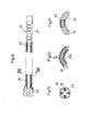
- a multitude of austenitic stainless steel coil line elements 2 are stranded along a predetermined circular line to form a flexible linear tube, a space of which serves as a central axial hollow portion 3.
- An entire length (Lt) of the flexible linear tube measures approx. 1.000 - 1.500 mm.
- the group of the coil line elements 2 is stranded under a strand-turn resistant load (torsion-resistant load) and heat treated to remove a residual stress appeared during the stranding and drawing operation.
- the wire-stranded hollow coil body 1 thus formed is provided with a high straightness having a straight configuration in free state devoid of the unfavorable roll or swell phenomenon.
- the wire-stranded hollow coil body 1 is further provided with a high rotation-following capability in which the rotation of the thin flexible wire at one end is soomthly and efficiently transmitted to the other end of the thin flexible wire when one end of the thin flexible wire is rotated around the axial hollow portion 3.
- the wire-stranded hollow coil body 1 is formed in accordance with the following first method (see Fig. 4). Namely, with the use of an ordinary wire rope stranding machine, a primary forming flexible linear tube R (referred simply to as "primary approximation R") is formed as a normal wire rope structure having a predetermined length. One end of the primary approximation R is set at a rotationally active chuck 11 of a stranding machine 10. The other end of the primary approximation R is arranged to be slidable along its lengthwise direction, and clamped by a slide type fixture chuck 12 loaded with a static weight W.
- first method see Fig. 4
- the torsion-resistant load under the tensile stress W is added to the primary approximation R set between the rotationally active chuck 11 and the slide type fixture chuck 12. Then, a conductor line 15 extended from an electric power generator 14 is connected between the rotationally active chuck 11 and the slide type fixture chuck 12, so as to apply an electric current to the primary approximation R to prepare for heat treatment of the primary approximation R.
- the primary approximation R set under the torsion-resistant load and the heat treatment is turned 300 times in the stranding direction and unwound 100 times in the reverse direction (stranded 200 (300-100) times resultantly) as shown at (A) in Table 2.
- the primary approximation R is heat treated due to its own electric resistor energized.
- an elongated core 4 is withdrawn from the primary approximation R to provide the axial hollow portion 3 so as to produce the wire-stranded hollow coil body 1.
- a stainless steel or nickel-titanium alloy core 5 are placed in the axial hollow portion 3 as a flexible wire component needed to form the guide wire.
- a single wound helical coil 9 is connected which is made from a radiopaque material to implement the fluorography while ensuring a high flexibility at the leading distal end of the wire-stranded hollow coil body 1 so as to provide a guide wire body of excellent quality.
- the core 5 is thermally bonded by a solder mass to substantially shape a semi-spherical bulge portion 6.
- the core 5 is thermally bonded by a plasma welding to substantially shape the same semi-spherical bulge portion 6.
- An outer surface of the guide wire body is ground by an electrolytic polishing (well-known means including whetstone grinding), the electrolytically polished surface is coated with a hydrophilic polymer film C applied thereon to provide a medical guide wire.
- electrolytic polishing well-known means including whetstone grinding
- a hydrophilic polymer film C applied thereon to provide a medical guide wire.
- the wire-stranded hollow coil body 1 is represented by the lightweight structure per a unit length and a smooth twisting manipulation based on the hollow wire tube configuration.
- an advantage specific to the first method of making the wire-stranded hollow coil body 1 is obtained.
- the coil line elements 2 made from the austenitic stainless steel (having a high coefficient of thermal expansion) and its outer surface electrolytically polished, secondary advantages are ensured. Namely, it is possible to provide the primary approximation R with a good drawability and heat-releasable capability at the time of thermally bonding bulge portion 6, so as to alleviate the residual stress in the primary approximation R to help stabilize the main advantages. Due to the electrolytically polishedsurface, it is possible to ensure a smooth and erosion-resistant surface to stabilize an improved performance as a main wire component of the medical equipment.
- the primary approximation R in which the coil line elements 2 are stranded along the predetermined circular line, is lengthwisely divided into three sections X, Y and Z, each of which has different number of strand turns as shown in Figs. 6 and 7.
- the section X has maximum strand turns provided at a hand access portion 8
- the section Z has a minimum strand turns provided at the leading distal end 7
- the section Y has a middle number of the strand turns provided at the halfway middle portion.
- the number of the strand turns progressively decreases from the section X through the section Y to the section Z, a helical pitch of which reversely increases respectively in the same order.
- the wire-stranded hollow coil body 1 is placed between the rotationally active chuck 11 and the fixture chuck 12 of the stranding machine 10, and a slidable clamp portion 14 is placed at the boundary between the sections X, Y and Z to clamp each section by paired clamp plates 15, 15 as shown in Fig. 8.
- a slidable clamp portion 14 is placed at the boundary between the sections X, Y and Z to clamp each section by paired clamp plates 15, 15 as shown in Fig. 8.
- Each of the sections X, Y and Z has the different strand turns and represents a bending characteristics depending on the strand turns provided among multi-mechanical properties.
- the hand access portion 8 has a maximum rigidity which is manipulated outside the patient's body as the flexible linear tube of the medical equipment.
- the leading distal end portion has a highly pliable and flexible property which is introduced into the vascular system and the somatic cavity.
- the primary approximation R has a bending rigidity (R1) successively reducing along the length dimension (L) to produce a high quality flexible linear tube as a functionally gradient substance which gradually shifts the property from a highly rigid section to a flexible section.
- Figs. 10 through 12 show a third embodiment of the invention in which the individually divided sections X, Y and Z are placed respectively at three heating devices 16A, 16B and 16C each having different heating condition.
- the primary approximation R is heat treated by energizing the devices 16A, 16B and 16C concurrently at the time of stranding the primary approximation R or after the primary approximation R is stranded, so as to remove the residual stress upon formation by a third method of making the wire-stranded hollow coil body 1.
- the sections X, Y and Z are heat treated differently to have the residual stresses removed in different degrees. This provides the wire-stranded hollow coil body 1 with the functionally gradient "tensile strength" and “bending rigidity (R2) " each gradually shifting in the lengthwise direction (L) so as to produce a high quality flexible linear tube as shown in Fig. 12.
- Figs. 13 through 17 show a fourth embodiment of the invention in which an outer surface of the group of the coil line elements 2 is ground in concentric relationship with the central axial hollow portion 3 to reduce an original outer diameter (DL) into a reduced outer diameter (DS).
- DL original outer diameter
- DS reduced outer diameter
- the wire-stranded hollow coil body 1 may be progressively decreased at its diametrical dimension in a cone-shaped fashion from the hand access portion 8 to the leading distal end 7 as shown at diametrical dimensions DS and D3 in Fig. 17.
- the flexible wire tube being soft at the front end and rigid at the rear end portion
- This realizes a functionally gradient structure which enables the manipulator to feel a smooth shift from the front soft property to the rear rigid property in proportion with a distance from the hand access portion 8.
- a bending rigidity and torque-transmitting capability can be improved to secure a smooth outer surface devoid of undulation between the neighboring coil line elements when compared to the structure in which the outer surface of the coil line elements 2 is not ground. This makes it possible to enhance the performance upon inserting the flexible wire tube into the vascular system and the somatic cavity.
- Fig. 18 shows a medical equipment in which the wire-stranded hollow coil body 1 is used as the flexible wire tube.
- Figs. 18, 19, 21, 22 and 25 show a flexible endscope 20 in which the wire-stranded hollow coil body 1 is used as a cloak tube 23.
- the endscope 20 has four elongated flexible cloak tubes 23 arranged between a front angle manipulator 21 and a rear manipulator 22 in a manner distinguishable from the first reference.
- Each of the cloak tubes 23 has a manipulator wire 24 surrounded by a flexible outer tube 25.
- the flexible endscope 20 is used to pass the human sigmoidal intenstine when inserted into the colon through the anus and the rectal.
- the wire-stranded hollow coil body 1 By applying the wire-stranded hollow coil body 1 to the endscope 20, the following advantage specific to the endscope 20 is obtained.
- a related art cloak tube 23A constructed from the single-wound coil structure (Fig. 20) so that a helical pitch gap P increases at its outer side of the cloak tube 23A to increase a tensile stress applied to the manipulator wire 24 when passing through the sigmoidal intenstine, it is possible to significantly reduce the tensile stress applied to the manipulator wire 24 because of its high flexibility of the cloak tubes 23 which readily adapt itself to the curved shape configuration in the present invention as shown in Fig. 21.
- Fig. 23 shows a relationship between a total bending angle ( ⁇ ) and an extension length (L) of the manipulator wire 24. It is found from a solid line in Fig. 23 that the flexible linear tube structure makes it possible to render the extension length (L) significantly small as compared to the related art extension length (Lp) (seventh reference) depicted by broken lines.
- the cloak tube 23 has an increased strand pitch between the coil line elements 2 as compared to a coil pitch of the related art cloak tube 23A as understood by Figs. 24 and 25.
- the structure makes it possible to significantly increase a relative friction angle ( ⁇ A) against the manipulator wire 24 as compared to a relative friction angle ( ⁇ B) of the related art cloak tube 23A against the manipulator wire 24. This reduces a frictional resistance between the cloak tube 23 and the manipulator wire 24 to greatly improve its push-pull maneuverability.
- By reversely stranding the cloak tube 23 against the manipulator wire 24 (stranding in an opposite direction), it is possible to determine the relative friction angle ( ⁇ A) to be around 90 degrees to improve the maneuverability.
- the flexible endscope 20 thus constructed has advantages that enables the leading end to smoothly pass through the sigmoidal intenstine so as to significantly improve a responsiveness and manipulatability of the front angle manipulator 21 actuated by the rear manipulator 22 (Fig. 18).
- Fig. 26 shows an endscope treating tool 30 in which a coil sheath 31 is arranged between a rear manipulator 33 and a front detain loop 34.
- the coil sheath 31 acts as the wire-stranded hollow coil body 1 which has a central hollow area, through which manipulator rope 32 is inserted.
- the endscope treating tool 30 provides the following advantages.
- the manipulator rope is forcibly stretched so as to deteriorate the manipulatability upon inserting the coil sheath into the somatic cavity, thus loosening a grip of the front detain loop 34 against a polyp 35 so as to disable the front detain loop 34 due to a failure of clutching the polyp 35.
- the subject endscope treating tool 30 has the front detain loop 34 (secured to the coil sheath 31) which stabilizes a grip against the polyp 35 with a good manipulatability so as to overcome the related art drawbacks to significantly improve a curability against the polyp 35.
- the subject endscope treating tool 30 has a sheath 42 arranged between a front biopsy cup 41 and a rear manipulator 40 in a manner distinguishable from the fifth reference.
- the sheath 42 serves as the wire-stranded hollow coil body 1 into which a manipulation rope 43 is inserted so as to rotationally move the front biopsy cup 41.
- the endscope treating tool 30 into which the wire-stranded hollow coil body 1 is incoporated as the sheath 42 provides the following advantages in addition the main advantages.
- the manipulation is further improved by using the structure (Figs. 13 - 17) in which the outer surface of the group of the coil line elements 2 is ground.
- the structure (Fig. 25) may be used in which the cloak tube 23 and the manipulator wire 24 are reversely stranded each other.
- Figs. 29 and 30 show a pressure sensor type guide wire 45 in which a pressure sensor 48 is provided at a front distal end of a flexible hollow tube wire 46 to measure a blood pressure or to monitor a blood pressure wave through a lead line 47 in a manner distinguishable from the sixth reference.
- the pressure sensor type guide wire 45 With the flexible hollow tube wire 46 into which the wire-stranded hollow coil body 1 is incoporated, the pressure sensor type guide wire 45 provides the following advantages in addition the main advantages.
- the flexible hollow tube wire prepared by the ordinary hollow coil body is subjected to the bending deformation so that the lead line 47 can be accidentally severed by a tensile force upon inserting it into the tortuous vascular system to confirm a post-operational condition after curing the coronary arterial stenosis (Ac) by way of example.
- Ac coronary arterial stenosis
- the description continues with respect to the structure represented by an "austenitic stainless steel” and the “ electrolytically polished outer surface of the coil line elements”.
- the martensitic stainless steel tends to harden with the heat treatment so as to likely stiffen the stranded coil section near the bulge portion 6 under the thermal influence produced at the time of soldering the bulge portion 6, thereby resultantly depriving the stranded coil section of the favorable flexibility.
- the ferritic stainless steel has the property referred to as "475 °C fragility" and having the property called as “sigma fragility" occurred when heated to approx.
- the ferritic stainless steel grows the crystallized particles to reveal "fragility in high temperature" when heated to 950 °C or more, thereby unfavorably deteriorating the quality as a catheter or catheter guide wire due to the thermal influence brought by thermally bonding the bulge portion 6.
- the austenitic stainless steel is less subjected to the texture transformation when heated, it is less affected by the heat generated when thermally bonding the bulge portion 6.
- the austenitic stainless steel has a relatively small thermal conductivity and a greater coefficient of thermal expansion which is approx. 1.5 - 1.6 times as great as that of the general stainless steel. This means that the thermal expansion and the thermal stress produced on the wire-stranded hollow coil body 1 by thermally bonding the bulge portion 6 are absorbed by a restricted portion of the wire-stranded hollow coil body 1 near the bulge portion 6. This alleviates the residual stress produced by thermally bonding the bulge portion 6, and thereby providing a good linearity and favorable flexibility with the restricted portion of the wire-stranded hollow coil body 1 near the bulge portion 6.
- the austenitic stainless steel While the martensitic stainless steel has a quench hardening property by which a tensile strength is augmented, the austenitic stainless steel increases its strength when drawn (work hardening) to be well-suited to the coil line elements of the wire-stranded hollow coil body 1. Since an electric resistance of the austenitic stainless steel is approx. five times as great as that of the carbon steel, and is approx. 1.6 times as great as that of the martensitic stainless steel. This decreases an intensity of the electric current necessary to thermally bond the bulge portion 6, whereby limiting the thermally bonding heat to a necessary minimum so as to lessen a twisting and torsional deformation under the influence of the heat generated by thermally bonding the bulge portion 6.
- the coil line elements 2 are magnetized when drawn by a dice tool with an outer surface of the coil line elements 2 mirror-finished. This attracts iron particles on the outer surface of the coil line elements 2 and collects foreign matters between the neighboring coil line elements 2 with the help of the Van del Waals' force based on the intermolecular affinity.
- the foreign matters are collected, in addition to a passively-caught rust from an opposed component part, a crevice corrosion occurs between the outer surface of the coil line elements 2 and the foreign matters so as to reduce a corrosion-resistant property.
- oxidized scales are removed to recover an original concentration of chromium component of the coil line elements 2 so as to resultantly improve the corrosion-resistant property.
- the wire-stranded hollow coil body 1 is applied not only to the medical equipment but also to a cloak tube into which a flexible wire is inserted.
- any material such as, for example, a general steel wire, a reinforced thin rope or the like can be applied to the coil line elements 2.
- the wire-stranded hollow coil body has a flexible hollow wire tube with a high rotation-following capability and a high straightness which provides such good properties as to be appropriately applicable to main constituents of various medical tools to undergo the treatment by inserting it into the vascular system and the somatic cavity.
- the method of making the wire-stranded hollow coil body enables manufacturers to mass produce high quality medical devices efficiently with a relatively low cost.
Landscapes
- Health & Medical Sciences (AREA)
- Life Sciences & Earth Sciences (AREA)
- Surgery (AREA)
- Veterinary Medicine (AREA)
- Engineering & Computer Science (AREA)
- Biomedical Technology (AREA)
- Heart & Thoracic Surgery (AREA)
- Biophysics (AREA)
- Animal Behavior & Ethology (AREA)
- General Health & Medical Sciences (AREA)
- Public Health (AREA)
- Pathology (AREA)
- Medical Informatics (AREA)
- Molecular Biology (AREA)
- Physics & Mathematics (AREA)
- Optics & Photonics (AREA)
- Nuclear Medicine, Radiotherapy & Molecular Imaging (AREA)
- Radiology & Medical Imaging (AREA)
- Hematology (AREA)
- Pulmonology (AREA)
- Anesthesiology (AREA)
- Immunology (AREA)
- Vascular Medicine (AREA)
- Media Introduction/Drainage Providing Device (AREA)
- Endoscopes (AREA)
- Ropes Or Cables (AREA)
- Heat Treatment Of Strip Materials And Filament Materials (AREA)
- Wire Processing (AREA)
Abstract
Description

| A | B | |
| dimensions | 18 coil line elements stranded (line diameter: 0.55mm) entire length: 4.500mm outer diameter of coil: 0.415mm inner diameter of coil: 0.305 | 8 coil line elements stranded (line diameter: 0.22mm) entire length: 4.500mm outer diameter of coil: 0.865mm inner diameter of coil: 0.425mm |
| stranded times | stranded 300 times but unwound 100 times | stranded 350 times but unwound 120 times |
| resistance heating | 2.8 Amp x 60 sec heating temp. :approx. 400-500 °C | 6.0 Amp x 60 sec heating temp.:approx. 400-500°C |
| static load weight | 3.6 kg | 13.6 kg |
Claims (14)
- A wire-stranded hollow coil body (1) comprising a multitude of coil line elements (2) stranded along a predetermined circular line to form a flexible linear tube having a central axial hollow portion (3), characterised in that said flexible linear tube is stranded under a strand-turn resistant load and heat treated to remove a residual stress upon formation so as to provide a high rotation-following capability and a high straightness.
- A wire-stranded hollow coil body (1) according to claim 1, wherein said flexible linear tube is lengthwisely divided into pluralistic sections (X, Y and Z), each of which has different number of strand turns.
- A wire-stranded hollow coil body (1) according to claim 1 or 2, wherein said flexible linear tube is lengthwisely divided into pluralistic sections (X, Y and Z), each of which has residual stresses removed in different degrees.
- A wire-stranded hollow coil body (1) according to claims 1 to 3, wherein an outer surface of said flexible linear tube is ground in concentric relationship with said predetermined circular line.
- A wire-stranded hollow coil body (1) according to any one of the preceding claims, wherein an outer surface of said flexible linear tube is ground by an electrolytic polishing in concentric relationship with said predetermined circular line.
- A wire-stranded hollow coil body (1) according to any one of the preceding claims, wherein said coil line elements (2) are austenitic stainless steel.
- A medical endscope (20) having an cloak tube (23) constituted by said wire-stranded hollow coil body (1) according to any one of claims 1 to 6.
- A medical endscope treating tool (30) having a coil sheath (31) constituted by said wire-stranded hollow coil body (1) according to any one of claims 1 to 6.
- A medical endscope treating tool (30) having a manipulating sheath portion (42) constituted by said wire-stranded hollow coil body (1) according to any one of claims 1 to 6.
- A medical guide wire (45) having a main wire body constituted by said wire-stranded hollow coil body (1) according to any one of claims 1 to 6.
- A pressure sensor type medical guide wire (45) having a main wire component constituted by said wire-stranded hollow coil body (1) according to any one of claims 1 to 6.
- A method of making a wire-stranded hollow coil body (1) comprising a multitude of coil line elements (2) stranded along a predetermined circular line to form a flexible linear tube having a central axial hollow portion (3),
the method comprising steps of;
clamping one end of a primary forming flexible linear tube (R) by means of a rotationally active chuck (11), and arranging the other end of said primary forming flexible linear tube (R) to be slidable in its lengthwise direction, and clamping said other end by a fixture chuck (12) to impart a tensile force with said primary forming flexible linear tube (R);
actuating said rotationally active chuck (11) to strand said primary forming flexible linear tube (R), and concurrently or thereafter heat treating said primary forming flexible linear tube (R) to remove a residual stress upon forming said coil line elements (2) by electrically conducting between said rotationally active chuck (11) and said fixture chuck (12). - A method of making a wire-stranded hollow coil body (1) comprising a multitude of coil line elements (2) stranded along a predetermined circular line to form a flexible linear tube having a central axial hollow portion (3),
the method comprising steps of;
clamping one end of a primary forming flexible linear tube (R) by means of a rotationally active chuck (11), and clamping halfway middle portions of said primary forming flexible linear tube (R) by means of middle clamp portions (14), and stranding said primary forming flexible linear tube (R) in different strand turns depending on spans between said rotationally active chuck (11) and each of said middle clamp portions (14). - A method of making a wire-stranded hollow coil body (1) comprising a multitude of coil line elements (2) stranded along a predetermined circular line to form a flexible linear tube (R) having a central axial hollow portion (3),
the method comprising steps of;
concurrently or after stranding a primary forming flexible linear tube (R), accommodating lengthwisely divided sections (X, Y and Z) of a primary forming flexible linear tube (R) into heating devices (16A, 16B and 16C), each of which has different heating condition depending on said lengthwisely divided sections (X, Y and Z), so as to heat treat said pluralistically divided sections (X, Y and Z) individually to have residual stresses removed in different degrees.
Applications Claiming Priority (2)
| Application Number | Priority Date | Filing Date | Title |
|---|---|---|---|
| JP2002358851A JP4098613B2 (en) | 2002-12-11 | 2002-12-11 | Hollow stranded wire coil body, medical instrument using the same, and manufacturing method thereof |
| JP2002358851 | 2002-12-11 |
Publications (3)
| Publication Number | Publication Date |
|---|---|
| EP1428547A2 true EP1428547A2 (en) | 2004-06-16 |
| EP1428547A3 EP1428547A3 (en) | 2006-10-04 |
| EP1428547B1 EP1428547B1 (en) | 2016-10-05 |
Family
ID=32322095
Family Applications (1)
| Application Number | Title | Priority Date | Filing Date |
|---|---|---|---|
| EP03255204.4A Expired - Lifetime EP1428547B1 (en) | 2002-12-11 | 2003-08-22 | A wire-stranded hollow coil body, medical equipment made therefrom and a method of making the same |
Country Status (4)
| Country | Link |
|---|---|
| US (2) | US7117703B2 (en) |
| EP (1) | EP1428547B1 (en) |
| JP (1) | JP4098613B2 (en) |
| CN (2) | CN101238968A (en) |
Cited By (2)
| Publication number | Priority date | Publication date | Assignee | Title |
|---|---|---|---|---|
| WO2014049519A1 (en) * | 2012-09-28 | 2014-04-03 | Koninklijke Philips N.V. | Lumen design for optimal fiber integration for optical shape sensing |
| WO2024003101A1 (en) | 2022-07-01 | 2024-01-04 | ETH Zürich | Magnetically steerable device for use inside of a mammalian body |
Families Citing this family (110)
| Publication number | Priority date | Publication date | Assignee | Title |
|---|---|---|---|---|
| EP1684628B1 (en) | 2003-11-21 | 2018-06-13 | St. Jude Medical Coordination Center BVBA | Sensor and guide wire assembly |
| NL1025274C2 (en) * | 2004-01-16 | 2005-07-19 | Univ Delft Tech | Instrument for fine-mechanical or fine-surgical applications. |
| JP4291233B2 (en) * | 2004-08-11 | 2009-07-08 | 朝日インテック株式会社 | Medical treatment tool |
| US7815580B2 (en) * | 2004-09-07 | 2010-10-19 | Stereotaxis, Inc. | Magnetic guidewire for lesion crossing |
| JP2006075232A (en) * | 2004-09-07 | 2006-03-23 | Terumo Corp | Wire for removing endovascular foreign body, and medical appliance |
| US7959660B2 (en) * | 2004-12-15 | 2011-06-14 | Cook Medical Technologies Llc | Multifilar cable catheter |
| JP4693091B2 (en) * | 2004-12-21 | 2011-06-01 | 朝日インテック株式会社 | Catheter and manufacturing method thereof |
| US20060213570A1 (en) * | 2005-03-08 | 2006-09-28 | Mr. Emilian Moldovan | Flexible Stiffner for PEX |
| JP4596530B2 (en) * | 2005-03-10 | 2010-12-08 | フィルメック株式会社 | Medical treatment tool |
| DE602006012464D1 (en) * | 2005-04-20 | 2010-04-08 | Cook Inc | MELTED JOINT FOR MEDICAL DEVICE |
| JP5033118B2 (en) * | 2005-04-20 | 2012-09-26 | クック メディカル テクノロジーズ エルエルシー | Medical delivery device having a tapered component |
| WO2006113863A2 (en) * | 2005-04-20 | 2006-10-26 | Cook Incorporated | Medical apparatus for rapid insertion |
| WO2006113869A2 (en) * | 2005-04-20 | 2006-10-26 | Cook Incorporated | Internal cannulated joint for medical delivery systems |
| JP4880251B2 (en) * | 2005-06-21 | 2012-02-22 | オリンパスメディカルシステムズ株式会社 | High frequency treatment tool |
| US8221390B2 (en) * | 2006-04-20 | 2012-07-17 | Cook Medical Technologies Llc | Medical device delivery system having a sheath with a flared strain relief member operatively coupled by a unidirectional handle |
| CN100457317C (en) * | 2006-05-25 | 2009-02-04 | 东莞市精工五金弹簧制造有限公司 | A processing method and processing device for a helical spring string |
| JP2007325748A (en) * | 2006-06-08 | 2007-12-20 | Pentax Corp | Endoscope |
| EP1955657B1 (en) * | 2007-02-08 | 2011-01-12 | Olympus Medical Systems Corp. | Treatment tool for endoscope |
| JP4526544B2 (en) * | 2007-02-08 | 2010-08-18 | オリンパスメディカルシステムズ株式会社 | Endoscopic treatment tool |
| US7655004B2 (en) | 2007-02-15 | 2010-02-02 | Ethicon Endo-Surgery, Inc. | Electroporation ablation apparatus, system, and method |
| US8657845B2 (en) | 2007-05-15 | 2014-02-25 | Cook Medical Technologies Llc | Multifilar cable catheter |
| US8579897B2 (en) | 2007-11-21 | 2013-11-12 | Ethicon Endo-Surgery, Inc. | Bipolar forceps |
| US8262655B2 (en) | 2007-11-21 | 2012-09-11 | Ethicon Endo-Surgery, Inc. | Bipolar forceps |
| US8568410B2 (en) | 2007-08-31 | 2013-10-29 | Ethicon Endo-Surgery, Inc. | Electrical ablation surgical instruments |
| US8372017B2 (en) * | 2007-10-30 | 2013-02-12 | General Electric Company | Multi-stranded trackable guidewire |
| US8480657B2 (en) | 2007-10-31 | 2013-07-09 | Ethicon Endo-Surgery, Inc. | Detachable distal overtube section and methods for forming a sealable opening in the wall of an organ |
| US20090112059A1 (en) | 2007-10-31 | 2009-04-30 | Nobis Rudolph H | Apparatus and methods for closing a gastrotomy |
| US8262680B2 (en) | 2008-03-10 | 2012-09-11 | Ethicon Endo-Surgery, Inc. | Anastomotic device |
| US20090270841A1 (en) * | 2008-04-24 | 2009-10-29 | Cook Incorporated | Catheters |
| US8679003B2 (en) | 2008-05-30 | 2014-03-25 | Ethicon Endo-Surgery, Inc. | Surgical device and endoscope including same |
| US8771260B2 (en) | 2008-05-30 | 2014-07-08 | Ethicon Endo-Surgery, Inc. | Actuating and articulating surgical device |
| US8403926B2 (en) | 2008-06-05 | 2013-03-26 | Ethicon Endo-Surgery, Inc. | Manually articulating devices |
| US8361112B2 (en) | 2008-06-27 | 2013-01-29 | Ethicon Endo-Surgery, Inc. | Surgical suture arrangement |
| US8888792B2 (en) | 2008-07-14 | 2014-11-18 | Ethicon Endo-Surgery, Inc. | Tissue apposition clip application devices and methods |
| US8262563B2 (en) | 2008-07-14 | 2012-09-11 | Ethicon Endo-Surgery, Inc. | Endoscopic translumenal articulatable steerable overtube |
| US8211125B2 (en) | 2008-08-15 | 2012-07-03 | Ethicon Endo-Surgery, Inc. | Sterile appliance delivery device for endoscopic procedures |
| US8529563B2 (en) | 2008-08-25 | 2013-09-10 | Ethicon Endo-Surgery, Inc. | Electrical ablation devices |
| US8241204B2 (en) | 2008-08-29 | 2012-08-14 | Ethicon Endo-Surgery, Inc. | Articulating end cap |
| US8480689B2 (en) | 2008-09-02 | 2013-07-09 | Ethicon Endo-Surgery, Inc. | Suturing device |
| US8409200B2 (en) | 2008-09-03 | 2013-04-02 | Ethicon Endo-Surgery, Inc. | Surgical grasping device |
| US8337394B2 (en) | 2008-10-01 | 2012-12-25 | Ethicon Endo-Surgery, Inc. | Overtube with expandable tip |
| US8157834B2 (en) | 2008-11-25 | 2012-04-17 | Ethicon Endo-Surgery, Inc. | Rotational coupling device for surgical instrument with flexible actuators |
| US8361066B2 (en) | 2009-01-12 | 2013-01-29 | Ethicon Endo-Surgery, Inc. | Electrical ablation devices |
| US20100191050A1 (en) * | 2009-01-23 | 2010-07-29 | Ethicon Endo-Surgery, Inc. | Variable length accessory for guiding a flexible endoscopic tool |
| US8252057B2 (en) | 2009-01-30 | 2012-08-28 | Ethicon Endo-Surgery, Inc. | Surgical access device |
| US9226772B2 (en) * | 2009-01-30 | 2016-01-05 | Ethicon Endo-Surgery, Inc. | Surgical device |
| CN101502693A (en) * | 2009-03-27 | 2009-08-12 | 北京天地和协科技有限公司 | Guiding wire |
| JP4863321B2 (en) * | 2009-06-16 | 2012-01-25 | 朝日インテック株式会社 | Medical guidewire |
| JP4993632B2 (en) | 2009-06-16 | 2012-08-08 | 朝日インテック株式会社 | Medical guidewire |
| US8100881B2 (en) | 2009-08-04 | 2012-01-24 | Cook Medical Technologies Llc | Flexible medical device for clot removal from small vessels |
| EP2561838B1 (en) | 2009-09-30 | 2017-05-31 | Cook Medical Technologies LLC | Short wire cable catheter |
| JP5437772B2 (en) * | 2009-10-27 | 2014-03-12 | 朝日インテック株式会社 | Medical treatment tool |
| US20110098704A1 (en) | 2009-10-28 | 2011-04-28 | Ethicon Endo-Surgery, Inc. | Electrical ablation devices |
| US8608652B2 (en) | 2009-11-05 | 2013-12-17 | Ethicon Endo-Surgery, Inc. | Vaginal entry surgical devices, kit, system, and method |
| JP5437778B2 (en) * | 2009-11-30 | 2014-03-12 | 朝日インテック株式会社 | Medical treatment tool |
| US8607660B2 (en) * | 2009-12-02 | 2013-12-17 | Ford Global Technologies, Llc | Vehicle braking assembly |
| US8496574B2 (en) | 2009-12-17 | 2013-07-30 | Ethicon Endo-Surgery, Inc. | Selectively positionable camera for surgical guide tube assembly |
| US8353487B2 (en) | 2009-12-17 | 2013-01-15 | Ethicon Endo-Surgery, Inc. | User interface support devices for endoscopic surgical instruments |
| US8506564B2 (en) | 2009-12-18 | 2013-08-13 | Ethicon Endo-Surgery, Inc. | Surgical instrument comprising an electrode |
| US9028483B2 (en) | 2009-12-18 | 2015-05-12 | Ethicon Endo-Surgery, Inc. | Surgical instrument comprising an electrode |
| JP5004256B2 (en) | 2009-12-25 | 2012-08-22 | 朝日インテック株式会社 | Medical guidewire |
| US9005198B2 (en) | 2010-01-29 | 2015-04-14 | Ethicon Endo-Surgery, Inc. | Surgical instrument comprising an electrode |
| JP5436266B2 (en) * | 2010-02-26 | 2014-03-05 | 朝日インテック株式会社 | Medical coil structure, manufacturing method thereof, medical endoscope formed with medical coil structure, medical treatment instrument, ultrasonic diagnostic medical catheter, and optical interference diagnostic medical catheter |
| JP5246884B2 (en) | 2010-08-10 | 2013-07-24 | 朝日インテック株式会社 | Guide wire |
| US10092291B2 (en) | 2011-01-25 | 2018-10-09 | Ethicon Endo-Surgery, Inc. | Surgical instrument with selectively rigidizable features |
| US9254169B2 (en) | 2011-02-28 | 2016-02-09 | Ethicon Endo-Surgery, Inc. | Electrical ablation devices and methods |
| US9314620B2 (en) | 2011-02-28 | 2016-04-19 | Ethicon Endo-Surgery, Inc. | Electrical ablation devices and methods |
| US9233241B2 (en) | 2011-02-28 | 2016-01-12 | Ethicon Endo-Surgery, Inc. | Electrical ablation devices and methods |
| WO2012125785A1 (en) | 2011-03-17 | 2012-09-20 | Ethicon Endo-Surgery, Inc. | Hand held surgical device for manipulating an internal magnet assembly within a patient |
| JP5459723B2 (en) * | 2011-12-26 | 2014-04-02 | 朝日インテック株式会社 | Medical guidewire |
| US8986199B2 (en) | 2012-02-17 | 2015-03-24 | Ethicon Endo-Surgery, Inc. | Apparatus and methods for cleaning the lens of an endoscope |
| US9427255B2 (en) | 2012-05-14 | 2016-08-30 | Ethicon Endo-Surgery, Inc. | Apparatus for introducing a steerable camera assembly into a patient |
| CA2911446C (en) | 2012-05-25 | 2020-10-13 | Vascular Imaging Corporation | Optical fiber pressure sensor |
| US9078662B2 (en) | 2012-07-03 | 2015-07-14 | Ethicon Endo-Surgery, Inc. | Endoscopic cap electrode and method for using the same |
| US9545290B2 (en) | 2012-07-30 | 2017-01-17 | Ethicon Endo-Surgery, Inc. | Needle probe guide |
| US10314649B2 (en) | 2012-08-02 | 2019-06-11 | Ethicon Endo-Surgery, Inc. | Flexible expandable electrode and method of intraluminal delivery of pulsed power |
| US9572623B2 (en) | 2012-08-02 | 2017-02-21 | Ethicon Endo-Surgery, Inc. | Reusable electrode and disposable sheath |
| US9119740B2 (en) * | 2012-08-09 | 2015-09-01 | Cook Medical Technologies Llc | Introducer sheath |
| US9277957B2 (en) | 2012-08-15 | 2016-03-08 | Ethicon Endo-Surgery, Inc. | Electrosurgical devices and methods |
| WO2014105578A1 (en) * | 2012-12-27 | 2014-07-03 | Volcano Corporation | Intravascular guidewire with hyper flexible distal end portion |
| US10098527B2 (en) | 2013-02-27 | 2018-10-16 | Ethidcon Endo-Surgery, Inc. | System for performing a minimally invasive surgical procedure |
| US9192499B2 (en) * | 2013-03-11 | 2015-11-24 | Cook Medical Technologies Llc | Inner catheter for a self-expanding medical device delivery system with a closed coil wire |
| US20140277005A1 (en) * | 2013-03-14 | 2014-09-18 | Covidien Lp | Medical device including flexible elongate torque-transmitting member |
| WO2015051003A1 (en) | 2013-10-04 | 2015-04-09 | Vascular Imaging Corporation | Imaging techniques using an imaging guidewire |
| US10537255B2 (en) | 2013-11-21 | 2020-01-21 | Phyzhon Health Inc. | Optical fiber pressure sensor |
| JP5780532B2 (en) * | 2013-12-06 | 2015-09-16 | 朝日インテック株式会社 | Medical guidewire |
| JP2015137428A (en) * | 2014-01-20 | 2015-07-30 | 朝日インテック株式会社 | Twisted wire and guide wire using the twisted wire |
| US9955878B2 (en) * | 2014-02-03 | 2018-05-01 | Volcano Corporation | Intravascular devices, systems, and methods having a core wire with embedded conductors |
| JP2016013269A (en) * | 2014-07-02 | 2016-01-28 | 朝日インテック株式会社 | Guide wire |
| US9782561B2 (en) | 2014-10-09 | 2017-10-10 | Vacular Solutions, Inc. | Catheter tip |
| US9636477B2 (en) | 2014-10-09 | 2017-05-02 | Vascular Solutions, Inc. | Catheter |
| US10258240B1 (en) | 2014-11-24 | 2019-04-16 | Vascular Imaging Corporation | Optical fiber pressure sensor |
| JP1539256S (en) * | 2015-04-30 | 2015-11-30 | ||
| JP5870227B1 (en) * | 2015-06-26 | 2016-02-24 | トクセン工業株式会社 | Rope for operation |
| JP5870226B1 (en) * | 2015-06-26 | 2016-02-24 | トクセン工業株式会社 | Rope for operation |
| US20170028167A1 (en) | 2015-07-30 | 2017-02-02 | Jeffrey M. Welch | Coronary guide catheter |
| JP7139091B2 (en) | 2015-09-01 | 2022-09-20 | 富士フィルター工業株式会社 | Metal porous body and metal filter |
| JP6654396B2 (en) * | 2015-10-07 | 2020-02-26 | オリンパス株式会社 | Connection structure |
| JP6423374B2 (en) * | 2016-01-07 | 2018-11-14 | トクセン工業株式会社 | Hollow stranded wire for operation |
| US10391274B2 (en) | 2016-07-07 | 2019-08-27 | Brian Giles | Medical device with distal torque control |
| US9918705B2 (en) | 2016-07-07 | 2018-03-20 | Brian Giles | Medical devices with distal control |
| JP6737652B2 (en) * | 2016-07-12 | 2020-08-12 | オリンパス株式会社 | Medical device wire and medical device |
| CN110312542B (en) * | 2017-03-10 | 2022-03-18 | 朝日英达科株式会社 | Probe needle |
| US10238834B2 (en) | 2017-08-25 | 2019-03-26 | Teleflex Innovations S.À.R.L. | Catheter |
| WO2019087356A1 (en) | 2017-11-02 | 2019-05-09 | オリンパス株式会社 | Variable rigidity device and endoscope |
| JP7067794B2 (en) * | 2019-08-01 | 2022-05-16 | 富士フィルター工業株式会社 | Method for manufacturing a metal porous body |
| CN111714069B (en) * | 2020-07-27 | 2025-01-07 | 湖南省华芯医疗器械有限公司 | Snake bone component and endoscope |
| WO2022113233A1 (en) * | 2020-11-26 | 2022-06-02 | 朝日インテック株式会社 | Guide wire |
| US11944759B2 (en) * | 2021-05-05 | 2024-04-02 | Covidien Lp | Catheter including variable stress relief structural support member |
| JP7796515B2 (en) * | 2021-11-25 | 2026-01-09 | 朝日インテック株式会社 | Two-layer coil structure |
Family Cites Families (32)
| Publication number | Priority date | Publication date | Assignee | Title |
|---|---|---|---|---|
| JPS5131303B2 (en) * | 1971-09-02 | 1976-09-06 | ||
| US4953553A (en) * | 1989-05-11 | 1990-09-04 | Advanced Cardiovascular Systems, Inc. | Pressure monitoring guidewire with a flexible distal portion |
| US5154705A (en) * | 1987-09-30 | 1992-10-13 | Lake Region Manufacturing Co., Inc. | Hollow lumen cable apparatus |
| US4932419A (en) * | 1988-03-21 | 1990-06-12 | Boston Scientific Corporation | Multi-filar, cross-wound coil for medical devices |
| JPH0683726B2 (en) * | 1990-10-12 | 1994-10-26 | 日本精線株式会社 | Guide wire for catheter |
| US5211636A (en) * | 1990-10-31 | 1993-05-18 | Lake Region Manufacturing Co., Inc. | Steerable infusion guide wire |
| US5984877A (en) * | 1991-02-05 | 1999-11-16 | Fleischhacker, Jr.; Joseph F. | Guide wire marker technique and coil spring marker technique |
| JPH04309371A (en) | 1991-04-08 | 1992-10-30 | Kato Hatsujo Kaisha Ltd | Medical tube and its production |
| US5741429A (en) * | 1991-09-05 | 1998-04-21 | Cardia Catheter Company | Flexible tubular device for use in medical applications |
| US6107004A (en) * | 1991-09-05 | 2000-08-22 | Intra Therapeutics, Inc. | Method for making a tubular stent for use in medical applications |
| JP2662848B2 (en) * | 1993-10-14 | 1997-10-15 | 株式会社パイオラックス | Manufacturing method of medical guidewire |
| US5437282A (en) * | 1993-10-29 | 1995-08-01 | Boston Scientific Corporation | Drive shaft for acoustic imaging catheters and flexible catheters |
| JP2626968B2 (en) * | 1993-11-30 | 1997-07-02 | 株式会社パイオラックス | Medical guidewire and method of manufacturing the same |
| JPH07213481A (en) | 1994-02-01 | 1995-08-15 | Fuji Photo Optical Co Ltd | Soft endoscope |
| JP2981976B2 (en) * | 1995-08-01 | 1999-11-22 | 朝日インテック株式会社 | Medical guidewire |
| US20030069522A1 (en) * | 1995-12-07 | 2003-04-10 | Jacobsen Stephen J. | Slotted medical device |
| US6436056B1 (en) * | 1996-02-28 | 2002-08-20 | Boston Scientific Corporation | Polymeric implements for torque transmission |
| US5840046A (en) * | 1996-06-21 | 1998-11-24 | Medtronic, Inc. | Guidewire having hydrophilic coating |
| JP3732911B2 (en) * | 1996-10-08 | 2006-01-11 | ペンタックス株式会社 | Endoscopic treatment tool |
| JPH10290803A (en) | 1997-02-21 | 1998-11-04 | Olympus Optical Co Ltd | Treating implement for endoscope |
| US6042553A (en) | 1997-04-15 | 2000-03-28 | Symbiosis Corporation | Linear elastic member |
| JPH1125758A (en) | 1997-07-07 | 1999-01-29 | Sanshu Densen Kk | Hollow compressed stranded wire |
| JPH1133004A (en) | 1997-07-15 | 1999-02-09 | Nippon B X I Kk | Guide wire with pressure sensor |
| JPH11104071A (en) | 1997-08-05 | 1999-04-20 | Olympus Optical Co Ltd | Treating instrument for endoscope |
| US6508803B1 (en) * | 1998-11-06 | 2003-01-21 | Furukawa Techno Material Co., Ltd. | Niti-type medical guide wire and method of producing the same |
| ATE305324T1 (en) * | 1999-03-29 | 2005-10-15 | William Cook Europe As | A GUIDE WIRE |
| ATE266442T1 (en) * | 1999-03-29 | 2004-05-15 | Cook William Europ | A GUIDE WIRE |
| CA2397697C (en) * | 2000-01-28 | 2008-04-15 | William Cook, Europe Aps | Endovascular medical device with plurality of wires |
| JP3765218B2 (en) * | 2000-02-03 | 2006-04-12 | フジノン株式会社 | Endoscope operation wire guide device |
| JP3717771B2 (en) * | 2000-08-29 | 2005-11-16 | オリンパス株式会社 | Coil pipe polishing method for endoscope |
| JP2002275774A (en) * | 2001-03-21 | 2002-09-25 | Asahi Intecc Co Ltd | Medical tubing, balloon catheters and medical guidewires |
| US6881194B2 (en) * | 2001-03-21 | 2005-04-19 | Asahi Intec Co., Ltd. | Wire-stranded medical hollow tube, and a medical guide wire |
-
2002
- 2002-12-11 JP JP2002358851A patent/JP4098613B2/en not_active Expired - Fee Related
-
2003
- 2003-07-02 US US10/611,664 patent/US7117703B2/en not_active Expired - Lifetime
- 2003-07-28 CN CNA2008100032100A patent/CN101238968A/en active Pending
- 2003-07-28 CN CNB031522807A patent/CN100399976C/en not_active Expired - Fee Related
- 2003-08-22 EP EP03255204.4A patent/EP1428547B1/en not_active Expired - Lifetime
-
2005
- 2005-08-12 US US11/202,036 patent/US20060014418A1/en not_active Abandoned
Cited By (2)
| Publication number | Priority date | Publication date | Assignee | Title |
|---|---|---|---|---|
| WO2014049519A1 (en) * | 2012-09-28 | 2014-04-03 | Koninklijke Philips N.V. | Lumen design for optimal fiber integration for optical shape sensing |
| WO2024003101A1 (en) | 2022-07-01 | 2024-01-04 | ETH Zürich | Magnetically steerable device for use inside of a mammalian body |
Also Published As
| Publication number | Publication date |
|---|---|
| CN100399976C (en) | 2008-07-09 |
| CN1506022A (en) | 2004-06-23 |
| EP1428547A3 (en) | 2006-10-04 |
| US20060014418A1 (en) | 2006-01-19 |
| EP1428547B1 (en) | 2016-10-05 |
| US20040116833A1 (en) | 2004-06-17 |
| CN101238968A (en) | 2008-08-13 |
| JP2004190167A (en) | 2004-07-08 |
| US7117703B2 (en) | 2006-10-10 |
| JP4098613B2 (en) | 2008-06-11 |
Similar Documents
| Publication | Publication Date | Title |
|---|---|---|
| EP1428547B1 (en) | A wire-stranded hollow coil body, medical equipment made therefrom and a method of making the same | |
| EP2263735B1 (en) | Medical Guidewire | |
| US9017268B2 (en) | Medical guidewire | |
| CA2247424C (en) | Intravascular guidewire | |
| EP1491230A2 (en) | A method of making a metallic thin wire and a medical tool into which the metallic thin wire is incorporated | |
| JP5490152B2 (en) | Guide wire | |
| US20110208092A1 (en) | Guidewire | |
| US20100318066A1 (en) | Medical guidewire | |
| JP2001501854A (en) | Guidewire for catheter | |
| JPH05168717A (en) | Intravascular guide wire and manufacturing method thereof | |
| CN101020093A (en) | A medical apparatus, tubular insertion device and a tubular insertion device having the same medical apparatus | |
| CN103354753A (en) | Medical guide wire | |
| EP1685869A1 (en) | A medical guide wire | |
| JP2009523481A (en) | Titanium / molybdenum alloy guide wire | |
| JP5473677B2 (en) | Guide wire | |
| US20150206622A1 (en) | Stranded wire and guidewire employing the same | |
| WO2013084599A1 (en) | Medical guide wire | |
| JP3756086B2 (en) | Manufacturing method of medical guide wire | |
| WO2018062155A1 (en) | Guide wire | |
| JP7545339B2 (en) | Multilayer Coil | |
| JP7858047B2 (en) | Guide wire | |
| JP3880472B2 (en) | Medical device wire | |
| JP2023007516A (en) | guide wire | |
| JP2001009041A (en) | Medical guide wire | |
| JP2001037869A (en) | Medical guide wire |
Legal Events
| Date | Code | Title | Description |
|---|---|---|---|
| PUAI | Public reference made under article 153(3) epc to a published international application that has entered the european phase |
Free format text: ORIGINAL CODE: 0009012 |
|
| AK | Designated contracting states |
Kind code of ref document: A2 Designated state(s): AT BE BG CH CY CZ DE DK EE ES FI FR GB GR HU IE IT LI LU MC NL PT RO SE SI SK TR |
|
| AX | Request for extension of the european patent |
Extension state: AL LT LV MK |
|
| PUAL | Search report despatched |
Free format text: ORIGINAL CODE: 0009013 |
|
| AK | Designated contracting states |
Kind code of ref document: A3 Designated state(s): AT BE BG CH CY CZ DE DK EE ES FI FR GB GR HU IE IT LI LU MC NL PT RO SE SI SK TR |
|
| AX | Request for extension of the european patent |
Extension state: AL LT LV MK |
|
| 17P | Request for examination filed |
Effective date: 20061128 |
|
| AKX | Designation fees paid |
Designated state(s): AT BE BG CH CY CZ DE DK EE ES FI FR GB GR HU IE IT LI LU MC NL PT RO SE SI SK TR |
|
| 17Q | First examination report despatched |
Effective date: 20071025 |
|
| GRAP | Despatch of communication of intention to grant a patent |
Free format text: ORIGINAL CODE: EPIDOSNIGR1 |
|
| INTG | Intention to grant announced |
Effective date: 20160511 |
|
| GRAS | Grant fee paid |
Free format text: ORIGINAL CODE: EPIDOSNIGR3 |
|
| GRAA | (expected) grant |
Free format text: ORIGINAL CODE: 0009210 |
|
| AK | Designated contracting states |
Kind code of ref document: B1 Designated state(s): AT BE BG CH CY CZ DE DK EE ES FI FR GB GR HU IE IT LI LU MC NL PT RO SE SI SK TR |
|
| REG | Reference to a national code |
Ref country code: GB Ref legal event code: FG4D |
|
| REG | Reference to a national code |
Ref country code: CH Ref legal event code: EP |
|
| REG | Reference to a national code |
Ref country code: AT Ref legal event code: REF Ref document number: 834082 Country of ref document: AT Kind code of ref document: T Effective date: 20161015 |
|
| REG | Reference to a national code |
Ref country code: IE Ref legal event code: FG4D |
|
| REG | Reference to a national code |
Ref country code: DE Ref legal event code: R096 Ref document number: 60349456 Country of ref document: DE |
|
| REG | Reference to a national code |
Ref country code: NL Ref legal event code: MP Effective date: 20161005 |
|
| REG | Reference to a national code |
Ref country code: AT Ref legal event code: MK05 Ref document number: 834082 Country of ref document: AT Kind code of ref document: T Effective date: 20161005 |
|
| PG25 | Lapsed in a contracting state [announced via postgrant information from national office to epo] |
Ref country code: SE Free format text: LAPSE BECAUSE OF FAILURE TO SUBMIT A TRANSLATION OF THE DESCRIPTION OR TO PAY THE FEE WITHIN THE PRESCRIBED TIME-LIMIT Effective date: 20161005 Ref country code: GR Free format text: LAPSE BECAUSE OF FAILURE TO SUBMIT A TRANSLATION OF THE DESCRIPTION OR TO PAY THE FEE WITHIN THE PRESCRIBED TIME-LIMIT Effective date: 20170106 |
|
| PG25 | Lapsed in a contracting state [announced via postgrant information from national office to epo] |
Ref country code: BE Free format text: LAPSE BECAUSE OF FAILURE TO SUBMIT A TRANSLATION OF THE DESCRIPTION OR TO PAY THE FEE WITHIN THE PRESCRIBED TIME-LIMIT Effective date: 20161005 Ref country code: FI Free format text: LAPSE BECAUSE OF FAILURE TO SUBMIT A TRANSLATION OF THE DESCRIPTION OR TO PAY THE FEE WITHIN THE PRESCRIBED TIME-LIMIT Effective date: 20161005 Ref country code: ES Free format text: LAPSE BECAUSE OF FAILURE TO SUBMIT A TRANSLATION OF THE DESCRIPTION OR TO PAY THE FEE WITHIN THE PRESCRIBED TIME-LIMIT Effective date: 20161005 Ref country code: NL Free format text: LAPSE BECAUSE OF FAILURE TO SUBMIT A TRANSLATION OF THE DESCRIPTION OR TO PAY THE FEE WITHIN THE PRESCRIBED TIME-LIMIT Effective date: 20161005 Ref country code: AT Free format text: LAPSE BECAUSE OF FAILURE TO SUBMIT A TRANSLATION OF THE DESCRIPTION OR TO PAY THE FEE WITHIN THE PRESCRIBED TIME-LIMIT Effective date: 20161005 Ref country code: PT Free format text: LAPSE BECAUSE OF FAILURE TO SUBMIT A TRANSLATION OF THE DESCRIPTION OR TO PAY THE FEE WITHIN THE PRESCRIBED TIME-LIMIT Effective date: 20170206 |
|
| REG | Reference to a national code |
Ref country code: DE Ref legal event code: R097 Ref document number: 60349456 Country of ref document: DE |
|
| PG25 | Lapsed in a contracting state [announced via postgrant information from national office to epo] |
Ref country code: SK Free format text: LAPSE BECAUSE OF FAILURE TO SUBMIT A TRANSLATION OF THE DESCRIPTION OR TO PAY THE FEE WITHIN THE PRESCRIBED TIME-LIMIT Effective date: 20161005 Ref country code: RO Free format text: LAPSE BECAUSE OF FAILURE TO SUBMIT A TRANSLATION OF THE DESCRIPTION OR TO PAY THE FEE WITHIN THE PRESCRIBED TIME-LIMIT Effective date: 20161005 Ref country code: DK Free format text: LAPSE BECAUSE OF FAILURE TO SUBMIT A TRANSLATION OF THE DESCRIPTION OR TO PAY THE FEE WITHIN THE PRESCRIBED TIME-LIMIT Effective date: 20161005 Ref country code: CZ Free format text: LAPSE BECAUSE OF FAILURE TO SUBMIT A TRANSLATION OF THE DESCRIPTION OR TO PAY THE FEE WITHIN THE PRESCRIBED TIME-LIMIT Effective date: 20161005 Ref country code: EE Free format text: LAPSE BECAUSE OF FAILURE TO SUBMIT A TRANSLATION OF THE DESCRIPTION OR TO PAY THE FEE WITHIN THE PRESCRIBED TIME-LIMIT Effective date: 20161005 |
|
| REG | Reference to a national code |
Ref country code: DE Ref legal event code: R082 Ref document number: 60349456 Country of ref document: DE Representative=s name: KLUNKER IP PATENTANWAELTE PARTG MBB, DE |
|
| PLBE | No opposition filed within time limit |
Free format text: ORIGINAL CODE: 0009261 |
|
| STAA | Information on the status of an ep patent application or granted ep patent |
Free format text: STATUS: NO OPPOSITION FILED WITHIN TIME LIMIT |
|
| PG25 | Lapsed in a contracting state [announced via postgrant information from national office to epo] |
Ref country code: IT Free format text: LAPSE BECAUSE OF FAILURE TO SUBMIT A TRANSLATION OF THE DESCRIPTION OR TO PAY THE FEE WITHIN THE PRESCRIBED TIME-LIMIT Effective date: 20161005 Ref country code: BG Free format text: LAPSE BECAUSE OF FAILURE TO SUBMIT A TRANSLATION OF THE DESCRIPTION OR TO PAY THE FEE WITHIN THE PRESCRIBED TIME-LIMIT Effective date: 20170105 |
|
| 26N | No opposition filed |
Effective date: 20170706 |
|
| PG25 | Lapsed in a contracting state [announced via postgrant information from national office to epo] |
Ref country code: SI Free format text: LAPSE BECAUSE OF FAILURE TO SUBMIT A TRANSLATION OF THE DESCRIPTION OR TO PAY THE FEE WITHIN THE PRESCRIBED TIME-LIMIT Effective date: 20161005 |
|
| REG | Reference to a national code |
Ref country code: CH Ref legal event code: PL |
|
| PG25 | Lapsed in a contracting state [announced via postgrant information from national office to epo] |
Ref country code: MC Free format text: LAPSE BECAUSE OF FAILURE TO SUBMIT A TRANSLATION OF THE DESCRIPTION OR TO PAY THE FEE WITHIN THE PRESCRIBED TIME-LIMIT Effective date: 20161005 |
|
| PG25 | Lapsed in a contracting state [announced via postgrant information from national office to epo] |
Ref country code: LI Free format text: LAPSE BECAUSE OF NON-PAYMENT OF DUE FEES Effective date: 20170831 Ref country code: CH Free format text: LAPSE BECAUSE OF NON-PAYMENT OF DUE FEES Effective date: 20170831 |
|
| REG | Reference to a national code |
Ref country code: FR Ref legal event code: ST Effective date: 20180430 |
|
| REG | Reference to a national code |
Ref country code: IE Ref legal event code: MM4A |
|
| PG25 | Lapsed in a contracting state [announced via postgrant information from national office to epo] |
Ref country code: LU Free format text: LAPSE BECAUSE OF NON-PAYMENT OF DUE FEES Effective date: 20170822 |
|
| PG25 | Lapsed in a contracting state [announced via postgrant information from national office to epo] |
Ref country code: IE Free format text: LAPSE BECAUSE OF NON-PAYMENT OF DUE FEES Effective date: 20170822 |
|
| PG25 | Lapsed in a contracting state [announced via postgrant information from national office to epo] |
Ref country code: FR Free format text: LAPSE BECAUSE OF NON-PAYMENT OF DUE FEES Effective date: 20170831 |
|
| PG25 | Lapsed in a contracting state [announced via postgrant information from national office to epo] |
Ref country code: HU Free format text: LAPSE BECAUSE OF FAILURE TO SUBMIT A TRANSLATION OF THE DESCRIPTION OR TO PAY THE FEE WITHIN THE PRESCRIBED TIME-LIMIT; INVALID AB INITIO Effective date: 20030822 |
|
| PG25 | Lapsed in a contracting state [announced via postgrant information from national office to epo] |
Ref country code: CY Free format text: LAPSE BECAUSE OF NON-PAYMENT OF DUE FEES Effective date: 20161005 |
|
| PG25 | Lapsed in a contracting state [announced via postgrant information from national office to epo] |
Ref country code: TR Free format text: LAPSE BECAUSE OF FAILURE TO SUBMIT A TRANSLATION OF THE DESCRIPTION OR TO PAY THE FEE WITHIN THE PRESCRIBED TIME-LIMIT Effective date: 20161005 |
|
| PGFP | Annual fee paid to national office [announced via postgrant information from national office to epo] |
Ref country code: GB Payment date: 20220823 Year of fee payment: 20 Ref country code: DE Payment date: 20220620 Year of fee payment: 20 |
|
| REG | Reference to a national code |
Ref country code: DE Ref legal event code: R071 Ref document number: 60349456 Country of ref document: DE |
|
| REG | Reference to a national code |
Ref country code: GB Ref legal event code: PE20 Expiry date: 20230821 |
|
| PG25 | Lapsed in a contracting state [announced via postgrant information from national office to epo] |
Ref country code: GB Free format text: LAPSE BECAUSE OF EXPIRATION OF PROTECTION Effective date: 20230821 |