EP1428461A1 - Coat hanger structure with variable width - Google Patents
Coat hanger structure with variable width Download PDFInfo
- Publication number
- EP1428461A1 EP1428461A1 EP03078823A EP03078823A EP1428461A1 EP 1428461 A1 EP1428461 A1 EP 1428461A1 EP 03078823 A EP03078823 A EP 03078823A EP 03078823 A EP03078823 A EP 03078823A EP 1428461 A1 EP1428461 A1 EP 1428461A1
- Authority
- EP
- European Patent Office
- Prior art keywords
- clothes hanger
- support
- hanger structure
- structure according
- arms
- Prior art date
- Legal status (The legal status is an assumption and is not a legal conclusion. Google has not performed a legal analysis and makes no representation as to the accuracy of the status listed.)
- Granted
Links
- 230000037431 insertion Effects 0.000 claims 1
- 238000003780 insertion Methods 0.000 claims 1
- 230000005484 gravity Effects 0.000 description 2
- 238000004026 adhesive bonding Methods 0.000 description 1
- 230000000694 effects Effects 0.000 description 1
- 238000004519 manufacturing process Methods 0.000 description 1
- 238000007789 sealing Methods 0.000 description 1
Images

Classifications
-
- A—HUMAN NECESSITIES
- A47—FURNITURE; DOMESTIC ARTICLES OR APPLIANCES; COFFEE MILLS; SPICE MILLS; SUCTION CLEANERS IN GENERAL
- A47G—HOUSEHOLD OR TABLE EQUIPMENT
- A47G25/00—Household implements used in connection with wearing apparel; Dress, hat or umbrella holders
- A47G25/14—Clothing hangers, e.g. suit hangers
- A47G25/44—Slidable hangers ; Adjustable hangers
- A47G25/441—Slidable hangers ; Adjustable hangers having adjustable width
- A47G25/442—Slidable hangers ; Adjustable hangers having adjustable width to support shouldered garments
-
- A—HUMAN NECESSITIES
- A47—FURNITURE; DOMESTIC ARTICLES OR APPLIANCES; COFFEE MILLS; SPICE MILLS; SUCTION CLEANERS IN GENERAL
- A47G—HOUSEHOLD OR TABLE EQUIPMENT
- A47G25/00—Household implements used in connection with wearing apparel; Dress, hat or umbrella holders
- A47G25/14—Clothing hangers, e.g. suit hangers
- A47G25/48—Hangers with clamps or the like, e.g. for trousers or skirts
- A47G25/483—Hangers with clamps or the like, e.g. for trousers or skirts with pivoting clamps or clips having axis of rotation parallel with the hanger arms
- A47G25/485—Hangers with clamps or the like, e.g. for trousers or skirts with pivoting clamps or clips having axis of rotation parallel with the hanger arms with a plurality of clips integral with, or supported by, the trouser-supporting bar
Definitions
- the present invention concerns a clothes hanger structure with adjustable width.
- the first type suitable for sleeve units, i.e. jackets, coats and similar, is provided typically with curved arms shaped roughly like the shoulders of a person, so that the sleeve unit rests on the upper part of said arms substantially in the same way as it is worn by the user.
- the second type suitable for trousers, skirts and similar, is provided typically with clips that open at the bottom to accommodate the garment, which is suspended from them and hangs taut due to the effect of gravity.
- a variation of this second type of clothes hanger is provided with a horizontal bar, with or without clips, on which the garment is folded.
- Naturally garments have very different dimensions according to the age and size of the end user. Said variability means that it is necessary either to have clothes hangers in different sizes or use a small clothes hanger also for large-size garments. In both cases the disadvantages arising from said situation are obvious.
- Adjustable clothes hangers have been proposed and exist on the market, particularly of the type for skirts and trousers, in which the garment supporting clips can slide on the outside of a horizontal bar along its whole length, thus permitting reciprocal positioning at the required distance.
- This solution apart from the fact that it is not applicable in the case of clothes hangers for sleeve units, has the disadvantage of leaving the user to find the minimum working distance between the clips, since the structure described allows them to slide along the entire bar until they are adjacent or reach a position of contact, not useful for supporting the garment.
- the present invention aims to overcome the disadvantages of the known clothes hangers, providing a clothes hanger structure with variable width capable of permitting standardisation of the product in the manufacturing phase and at the same time supporting the garment perfectly both during transport and industrial or domestic storage.
- an adjustable clothes hanger structure comprising upper hanging means, two symmetrical side arms that extend from the centre point of said structure and movable means of support for the garment, characterised in that said movable means of support are fixed integrally to elements sliding in cavities provided inside said arms, thus permitting width adjustment of said movable means of support for the garment.
- a first embodiment of the invention consists in a clothes hanger structure 10 provided with upper hanging means, typically consisting of a hook 12 fixed to the centre point 14 of the structure itself.
- the structure also comprises two symmetrical arms 16, 16', extending laterally from the centre point 14 and slanting downwards.
- each arm 16, 16' is provided with movable support elements 18, 18' for the garment which, according to said first embodiment of the invention, is typically a sleeve unit.
- the supporting elements 18, 18' have a curved shape roughly similar to a person's shoulders, for appropriate positioning of the garment.
- elongated cavities 20, 20' are provided in the arms 18, 18' extending from the end of the arms to a roughly intermediate area of each arm.
- Said cavities 20, 20' constitute the seats of sliding fixing elements 22, 22', which slide like shuttles in contact with the walls of the cavities 20, 20', therefore being capable of maintaining any intermediate or extreme position inside the cavities.
- 16' longitudinal apertures 24,24' are provided through which projections 26,26' of the shuttles 22, 22' emerge.
- projections 26, 26' are provided with protruding edges 28, 28' that constitute fixing and supporting elements for the supporting means 18, 18' by engaging in corresponding seats 30, 30' provided in the lower part of the supporting means 18, 18.
- Figure 3 illustrates a preferred embodiment of a detail of an arm 16 of the clothes hanger structure according to the invention.
- the sliding fixing element or shuttle 22 made preferably of pliable plastic, is provided with a lower tooth 32 that constitutes a forced contact element with the lower wall of the cavity 20.
- Wall notches 34 are provided in such lower wall functioning as stops for the tooth 32 with respect to sliding of the shuttle 22 in the cavity of the arm. In this way it is possible to obtain a number of predefined stop positions for the shuttle 22 and therefore of the garment means of support integral with it, each of said positions corresponding for example to a garment size.
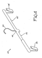
- FIG. 4 illustrates a second embodiment of the invention, typically designed for garments such as trousers or skirts.
- a clothes hanger structure 40 is provided with an upper hook 42 fixed to the centre point 44 of the structure.
- the structure also comprises two symmetrical arms 46, 46' that extend horizontally along the same axis from the centre point 44.
- each arm 46, 46' is provided with movable means of support 48, 48' of the garment which in this case consists typically of skirts or trousers.
- the means of support 48, 48' are substantially clips facing downwards, from which the garment is hung so that it is kept straight and without creases, thanks to gravity.
- the arms 46, 46' are provided with elongated cavities 50, 50' that extend from the ends of the arms to an approximately intermediate area of each arm.
- Said cavities 50, 50' constitute the seats of sliding fixing elements 52, 52' which slide like shuttles in contact with the walls of the cavities 50, 50', therefore capable of maintaining any intermediate or extreme position inside the cavities.
- longitudinal apertures 54, 54' are provided through which clips emerge integral with the sliding elements 52, 52', which constitute the actual means of support for the garment.
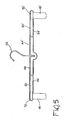
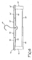
- Figure 6 illustrates a third embodiment of the invention, similar to that of Figures 4 and 5 as regards the structure of the arms and the sliding elements 52, 52'.
- a pair of connecting elements 56, 56' fixed integrally with the sliding elements 52, 52', emerges from the apertures 54, 54' of the arms and sustains the means of support which in this embodiment of the invention consist of a pair of horizontal bars 58, 58' of different diameter, inserted telescopically one inside the other.
- the bar 58 is fixed to the connecting element 56 and therefore runs integrally with the shuttle 52, while the bar 58' is connected integrally with the connection element 56' and runs integrally with the shuttle 52'. It is therefore possible to telescopically extend or retract the pair of bars 58, 58', adjusting the width of the garment means of support.
- Both the clothes hanger structure of Figures 1 and 2 and that of Figures 4 and 5 are preferably made by constructing two equal half-shells according to the longitudinal section, as illustrated in Figures 2 and 5, preferably made of plastic.
- the sliding fixing elements 22, 22' or 52, 52' are housed in the respective cavities 20, 20' or 50, 50' in this phase, with the garment means of support emerging from the elongated holes 24, 24' or 54, 54'.
- the other half- shell of the structure is then assembled to its corresponding half and fixed to it, for example by slotting pins into corresponding holes provided along the inner edges of the half-shells, or by gluing, heat sealing or other appropriate fixing system.
- the means of support 18, 18' are then applied to the upper part of the arms (16, 16') by slotting the edge 28, 28' into the corresponding seats 30, 30' of the means of support.
- Hanging means 12 and 42 are preferably of the type having a variable height, as described in copending Italian patent application no. BG2002U000014 filed on 10 December 2002.
Abstract
Description
- The present invention concerns a clothes hanger structure with adjustable width.
- Basically two types of clothes hanger exist. The first type, suitable for sleeve units, i.e. jackets, coats and similar, is provided typically with curved arms shaped roughly like the shoulders of a person, so that the sleeve unit rests on the upper part of said arms substantially in the same way as it is worn by the user. The second type, suitable for trousers, skirts and similar, is provided typically with clips that open at the bottom to accommodate the garment, which is suspended from them and hangs taut due to the effect of gravity. A variation of this second type of clothes hanger is provided with a horizontal bar, with or without clips, on which the garment is folded.
- Naturally garments have very different dimensions according to the age and size of the end user. Said variability means that it is necessary either to have clothes hangers in different sizes or use a small clothes hanger also for large-size garments. In both cases the disadvantages arising from said situation are obvious.
- Adjustable clothes hangers have been proposed and exist on the market, particularly of the type for skirts and trousers, in which the garment supporting clips can slide on the outside of a horizontal bar along its whole length, thus permitting reciprocal positioning at the required distance. This solution, apart from the fact that it is not applicable in the case of clothes hangers for sleeve units, has the disadvantage of leaving the user to find the minimum working distance between the clips, since the structure described allows them to slide along the entire bar until they are adjacent or reach a position of contact, not useful for supporting the garment.
- The present invention aims to overcome the disadvantages of the known clothes hangers, providing a clothes hanger structure with variable width capable of permitting standardisation of the product in the manufacturing phase and at the same time supporting the garment perfectly both during transport and industrial or domestic storage.
- The above aim is achieved by means of an adjustable clothes hanger structure, comprising upper hanging means, two symmetrical side arms that extend from the centre point of said structure and movable means of support for the garment, characterised in that said movable means of support are fixed integrally to elements sliding in cavities provided inside said arms, thus permitting width adjustment of said movable means of support for the garment.
- The present invention will now be described with reference to the attached drawings, provided as a non-restrictive example, in which:
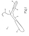
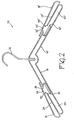
- Figure 1 is a perspective view of a clothes hanger structure according to a first embodiment of the invention;
- Figure 2 is a longitudinal section view of the clothes hanger structure according to Figure 1;
- Figure 3 is a longitudinal section view of a detail of the clothes hanger structure of Figures 1 and 2;
- Figure 4 is a perspective view of a clothes hanger structure according to a second embodiment of the invention;
- Figure 5 is a longitudinal section view of the clothes hanger structure according to Figure 4;
- Figure 6 is a longitudinal section view of a clothes hanger structure according to a third embodiment of the invention.
- As shown in Figure 1, a first embodiment of the invention consists in a
clothes hanger structure 10 provided with upper hanging means, typically consisting of ahook 12 fixed to thecentre point 14 of the structure itself. The structure also comprises twosymmetrical arms 16, 16', extending laterally from thecentre point 14 and slanting downwards. In their distal part, eacharm 16, 16' is provided withmovable support elements 18, 18' for the garment which, according to said first embodiment of the invention, is typically a sleeve unit. The supportingelements 18, 18' have a curved shape roughly similar to a person's shoulders, for appropriate positioning of the garment. - As illustrated in Figure 2,
elongated cavities 20, 20' are provided in thearms 18, 18' extending from the end of the arms to a roughly intermediate area of each arm. Saidcavities 20, 20' constitute the seats of slidingfixing elements 22, 22', which slide like shuttles in contact with the walls of thecavities 20, 20', therefore being capable of maintaining any intermediate or extreme position inside the cavities. In the upper part of thearms 16, 16'longitudinal apertures 24,24' are provided through whichprojections 26,26' of theshuttles 22, 22' emerge.Such projections 26, 26' are provided withprotruding edges 28, 28' that constitute fixing and supporting elements for the supportingmeans 18, 18' by engaging in corresponding seats 30, 30' provided in the lower part of the supportingmeans arms 16, 16', theshuttles 22, 22' will slide in their respective cavities, with the possibility of choosing a more or less extended position of thesupport elements 18, 18' of the garment, therefore adjusting the width of the clothes hanger as required. - Figure 3 illustrates a preferred embodiment of a detail of an
arm 16 of the clothes hanger structure according to the invention. In it, the sliding fixing element orshuttle 22, made preferably of pliable plastic, is provided with a lower tooth 32 that constitutes a forced contact element with the lower wall of thecavity 20.Wall notches 34 are provided in such lower wall functioning as stops for the tooth 32 with respect to sliding of theshuttle 22 in the cavity of the arm. In this way it is possible to obtain a number of predefined stop positions for theshuttle 22 and therefore of the garment means of support integral with it, each of said positions corresponding for example to a garment size. - Figure 4 illustrates a second embodiment of the invention, typically designed for garments such as trousers or skirts. According to said embodiment, a
clothes hanger structure 40 is provided with anupper hook 42 fixed to thecentre point 44 of the structure. The structure also comprises twosymmetrical arms 46, 46' that extend horizontally along the same axis from thecentre point 44. In their distal part, eacharm 46, 46' is provided with movable means ofsupport 48, 48' of the garment which in this case consists typically of skirts or trousers. The means ofsupport 48, 48' are substantially clips facing downwards, from which the garment is hung so that it is kept straight and without creases, thanks to gravity. - As illustrated in Figure 5, the
arms 46, 46' are provided withelongated cavities 50, 50' that extend from the ends of the arms to an approximately intermediate area of each arm. Saidcavities 50, 50' constitute the seats of slidingfixing elements 52, 52' which slide like shuttles in contact with the walls of thecavities 50, 50', therefore capable of maintaining any intermediate or extreme position inside the cavities. In the lower part of thearms 46, 46'longitudinal apertures 54, 54' are provided through which clips emerge integral with thesliding elements 52, 52', which constitute the actual means of support for the garment. It is obvious that by moving thesliding elements 52, 52' in a direction parallel to thearms 46, 46', they slide in theirrespective cavities 50, 50' with the possibility of choosing a more or less extended position of the means ofsupport 48, 48' of the garment, therefore adjusting the width of the clothes hanger as required. - Similarly to the illustration in Figure 3, also in the embodiment of Figures 4 and 5 it is possible to provide the
sliding elements 52, 52' with protruding teeth for a forced sliding movement in thecavities 50, 50' and preferential housing in corresponding notches provided in the upper part of the cavities. Said form of embodiment is not illustrated as it is conceptually identical to the ones illustrated in Figure 3. - Figure 6 illustrates a third embodiment of the invention, similar to that of Figures 4 and 5 as regards the structure of the arms and the
sliding elements 52, 52'. A pair of connectingelements 56, 56', fixed integrally with thesliding elements 52, 52', emerges from theapertures 54, 54' of the arms and sustains the means of support which in this embodiment of the invention consist of a pair ofhorizontal bars 58, 58' of different diameter, inserted telescopically one inside the other. In particular, thebar 58 is fixed to the connectingelement 56 and therefore runs integrally with theshuttle 52, while the bar 58' is connected integrally with the connection element 56' and runs integrally with the shuttle 52'. It is therefore possible to telescopically extend or retract the pair ofbars 58, 58', adjusting the width of the garment means of support. - Both the clothes hanger structure of Figures 1 and 2 and that of Figures 4 and 5 are preferably made by constructing two equal half-shells according to the longitudinal section, as illustrated in Figures 2 and 5, preferably made of plastic. The sliding
fixing elements respective cavities elongated holes support 18, 18' are then applied to the upper part of the arms (16, 16') by slotting theedge 28, 28' into the corresponding seats 30, 30' of the means of support. - Hanging means 12 and 42 are preferably of the type having a variable height, as described in copending Italian patent application no. BG2002U000014 filed on 10 December 2002.
- Some preferential embodiments of the invention have been described, but they can obviously be further modified and varied within the context of the inventive idea.
Claims (11)
- Adjustable clothes hanger structure (10, 40) comprising upper hanging means (12, 42), two symmetrical side arms (16,16'; 46,46') extending from the centre point (14, 44) of said structure and movable means (18,18'; 48,48'; 58,58') for supporting the garment, characterised in that said movable supporting means (18,18'; 48,48'; 58,58') are fixed integrally with sliding elements (22,22'; 52,52') in cavities (20,20'; 50,50') provided inside said arms (16,16'; 46,46') so as to permit width adjustment of said movable means of support (18,18'; 48,48'; 58,58') for the garment.
- Clothes hanger structure according to claim 1, characterised in that said movable means of support (18, 18') are superimposed on said arms (16, 16') and are connected to projections (26, 26') of said sliding elements (22, 22'), said projections protruding from longitudinal apertures (24, 24') provided in the upper part of said arms (16, 16').
- Clothes hanger structure according to claim 2, characterised in that said symmetrical side arms (16, 16') slant downwards and said movable means of support (18, 18') have a curved shape for optimal support of the garment.
- Clothes hanger structure according to claim 2, characterised in that the connection of said movable means of support (18, 18') to said projections (26, 26') of said sliding elements (22, 22') is provided by slotting a protruding edge (28, 28') of said projections into corresponding seats (30, 30') provided in the lower part of the means of support (18, 18').
- Clothes hanger structure according to claim 1, characterised in that said sliding elements (22,22'; 52,52') are provided with at least one tooth (32) in forced contact with a wall of the cavities (20,20'; 22,22') in which notches (34) are provided, designed to engage said tooth (32) to define a number of stop positions of said sliding elements (22,22'; 52,52').
- Clothes hanger structure according to claim 1, characterised in that said upper hanging means consists of a hook fixed to the centre point of the structure.
- Clothes hanger structure according to claim 1, characterised in that said symmetrical side arms (46, 46') extend horizontally along the same axis, said movable means of support (48,48'; 58,58') are positioned below said arms (46, 46') and are connected to said sliding elements (52, 52') via longitudinal apertures (54, 54') provided in the lower walls of the cavities (50,50').
- Clothes hanger structure according to claim 7, characterised in that said movable means of support (48, 48') are provided with clips for gripping the garment.
- Clothes hanger structure according to claim 7, characterised in that said sliding elements (52, 52') are provided with at least one tooth in forced contact with a wall of the cavities (50, 50') in which notches are provided, designed to engage said tooth to define a number of stop positions of said sliding elements (52, 52').
- Clothes hanger structure according to claim 7, characterised in that said movable means of support consist of a pair of bars (58, 58') inserted telescopically one inside the other, each fixed integrally to one of said sliding elements (52, 52') by means of connection elements (56, 56').
- Clothes hanger structure according to claim 1, characterised in that it is made of two symmetrical half-shells along the longitudinal axis, said half-shells being assembled after the insertion of said sliding elements (22,22'; 52,52') in the corresponding cavities (20,20'; 50,50').
Priority Applications (1)
| Application Number | Priority Date | Filing Date | Title |
|---|---|---|---|
| SI200330495T SI1428461T1 (en) | 2002-12-10 | 2003-12-04 | Coat hanger structure with variable width |
Applications Claiming Priority (2)
| Application Number | Priority Date | Filing Date | Title |
|---|---|---|---|
| ITBG20020043 | 2002-12-10 | ||
| IT000043A ITBG20020043A1 (en) | 2002-12-10 | 2002-12-10 | STRUCTURE OF HANGER WITH ADJUSTABLE WIDTH. |
Publications (2)
| Publication Number | Publication Date |
|---|---|
| EP1428461A1 true EP1428461A1 (en) | 2004-06-16 |
| EP1428461B1 EP1428461B1 (en) | 2006-08-02 |
Family
ID=32321402
Family Applications (1)
| Application Number | Title | Priority Date | Filing Date |
|---|---|---|---|
| EP03078823A Expired - Lifetime EP1428461B1 (en) | 2002-12-10 | 2003-12-04 | Coat hanger structure with variable width |
Country Status (7)
| Country | Link |
|---|---|
| US (1) | US7097081B2 (en) |
| EP (1) | EP1428461B1 (en) |
| AT (1) | ATE334617T1 (en) |
| DE (1) | DE60307210T2 (en) |
| ES (1) | ES2269910T3 (en) |
| IT (1) | ITBG20020043A1 (en) |
| SI (1) | SI1428461T1 (en) |
Cited By (2)
| Publication number | Priority date | Publication date | Assignee | Title |
|---|---|---|---|---|
| GB2464831A (en) * | 2008-11-01 | 2010-05-05 | Nick Lewis | Adjustable hanger with trouser bar |
| CN108820745A (en) * | 2018-07-27 | 2018-11-16 | 湖州三条鱼服饰有限公司 | A kind of garment production processing clothes hanger diverter |
Families Citing this family (8)
| Publication number | Priority date | Publication date | Assignee | Title |
|---|---|---|---|---|
| ITVI20030054A1 (en) * | 2003-03-19 | 2004-09-20 | Mainetti Tecnologie Spa | PERFECTED HANGER. |
| US20080179355A1 (en) * | 2006-12-05 | 2008-07-31 | The Build-Up Plastic & Metal Co., Ltd. | Non-slip garment hanger |
| US8256650B2 (en) * | 2009-09-29 | 2012-09-04 | Chad Sokol | Extendible garment hanger |
| US8186547B2 (en) | 2010-03-24 | 2012-05-29 | Richard P Morawietz | Adjustable width hanger |
| US8770452B1 (en) | 2011-09-28 | 2014-07-08 | Steven T. Gottlieb | Expandable clothes hanger |
| US9282839B2 (en) | 2014-07-24 | 2016-03-15 | Murad Rakhamimov | Hanger |
| USD786568S1 (en) | 2015-07-24 | 2017-05-16 | Murad Rahkamimov | Interlocking hanger |
| US10786102B2 (en) | 2016-03-03 | 2020-09-29 | Kyle L. Baltz | Single hand operated collapsing hanger |
Citations (5)
| Publication number | Priority date | Publication date | Assignee | Title |
|---|---|---|---|---|
| FR636467A (en) * | 1928-04-10 | |||
| GB2262224A (en) * | 1991-12-11 | 1993-06-16 | Chen Hsin Hui | Adjustable garment hanger |
| US5456391A (en) * | 1994-10-27 | 1995-10-10 | Chang; John | Suit hanger with adjustable shoulders |
| DE29710306U1 (en) * | 1997-06-12 | 1997-08-14 | Braitrim Uk Ltd | Hangers |
| DE20008718U1 (en) * | 1999-05-18 | 2000-09-21 | Braitrim Deutschland Gmbh | Tension bars for pants, skirts and the like |
Family Cites Families (9)
| Publication number | Priority date | Publication date | Assignee | Title |
|---|---|---|---|---|
| GB8724851D0 (en) * | 1987-10-23 | 1987-11-25 | Braitrim London Ltd | Expandable garment hanger |
| WO1994002056A1 (en) * | 1992-07-16 | 1994-02-03 | David Cleveland Bell | Adjustable hanger |
| US5718358A (en) * | 1994-07-20 | 1998-02-17 | Sedo Trust | Extensible clothes hanger |
| GB9721102D0 (en) * | 1997-10-06 | 1997-12-03 | Woodworth Peter M | Garment hangers |
| US5941429A (en) * | 1998-03-02 | 1999-08-24 | Charles R. Koons | Extendable hanger |
| US6068166A (en) * | 1998-07-02 | 2000-05-30 | Kilian; Jeanne | Adjustable garment hanger |
| US5975385A (en) * | 1998-09-14 | 1999-11-02 | See; Benito L. | Extensible clothes hanger |
| US6409058B1 (en) * | 2000-10-26 | 2002-06-25 | Peter Ar-Fu Lam | Adjustable garment hanger |
| US6722538B1 (en) * | 2002-10-16 | 2004-04-20 | Hayward Autry | Adjustable clothes hanger |
-
2002
- 2002-12-10 IT IT000043A patent/ITBG20020043A1/en unknown
-
2003
- 2003-12-04 SI SI200330495T patent/SI1428461T1/en unknown
- 2003-12-04 DE DE60307210T patent/DE60307210T2/en not_active Expired - Fee Related
- 2003-12-04 AT AT03078823T patent/ATE334617T1/en not_active IP Right Cessation
- 2003-12-04 ES ES03078823T patent/ES2269910T3/en not_active Expired - Lifetime
- 2003-12-04 EP EP03078823A patent/EP1428461B1/en not_active Expired - Lifetime
- 2003-12-10 US US10/730,894 patent/US7097081B2/en not_active Expired - Fee Related
Patent Citations (5)
| Publication number | Priority date | Publication date | Assignee | Title |
|---|---|---|---|---|
| FR636467A (en) * | 1928-04-10 | |||
| GB2262224A (en) * | 1991-12-11 | 1993-06-16 | Chen Hsin Hui | Adjustable garment hanger |
| US5456391A (en) * | 1994-10-27 | 1995-10-10 | Chang; John | Suit hanger with adjustable shoulders |
| DE29710306U1 (en) * | 1997-06-12 | 1997-08-14 | Braitrim Uk Ltd | Hangers |
| DE20008718U1 (en) * | 1999-05-18 | 2000-09-21 | Braitrim Deutschland Gmbh | Tension bars for pants, skirts and the like |
Cited By (2)
| Publication number | Priority date | Publication date | Assignee | Title |
|---|---|---|---|---|
| GB2464831A (en) * | 2008-11-01 | 2010-05-05 | Nick Lewis | Adjustable hanger with trouser bar |
| CN108820745A (en) * | 2018-07-27 | 2018-11-16 | 湖州三条鱼服饰有限公司 | A kind of garment production processing clothes hanger diverter |
Also Published As
| Publication number | Publication date |
|---|---|
| ITBG20020043A1 (en) | 2004-06-11 |
| DE60307210D1 (en) | 2006-09-14 |
| EP1428461B1 (en) | 2006-08-02 |
| DE60307210T2 (en) | 2007-07-05 |
| ATE334617T1 (en) | 2006-08-15 |
| US20040129743A1 (en) | 2004-07-08 |
| ES2269910T3 (en) | 2007-04-01 |
| US7097081B2 (en) | 2006-08-29 |
| SI1428461T1 (en) | 2006-12-31 |
Similar Documents
| Publication | Publication Date | Title |
|---|---|---|
| US7097081B2 (en) | Coat hanger structure with variable width | |
| WO1994002056A1 (en) | Adjustable hanger | |
| US6065652A (en) | Adjustable clothing hanger | |
| CA1318296C (en) | Adjustable garment hanger | |
| US6338426B1 (en) | Garment hanger | |
| EP1498054A2 (en) | Adjustable clothes hanger | |
| US5072837A (en) | Hinged multiple garment hanger | |
| US4953717A (en) | Hinged multiple garment hanger | |
| US7188741B1 (en) | Over the door support apparatus | |
| US4892238A (en) | Clothes press hanger | |
| US20130320051A1 (en) | Garment hanger with adjustable shoulder section and non-slip crease free horizontal pants section | |
| WO2018045235A1 (en) | Clothes hanger having extension rods | |
| KR20050003991A (en) | Hanger | |
| US2504562A (en) | Coat hanger | |
| US381888A (en) | Combined coat and pantaloons supporter | |
| US3963155A (en) | Dual garment hangers | |
| US1241346A (en) | Folding garment-hanger. | |
| EP1658793A1 (en) | Open clothes hangers system | |
| US699080A (en) | Garment-hanger. | |
| JP5783350B2 (en) | Clothes dryer | |
| US730263A (en) | Garment-hanger. | |
| US609743A (en) | Garment-hanger | |
| KR200287318Y1 (en) | A clothes hanger for pants | |
| KR200241124Y1 (en) | Trousers'rack | |
| US5996862A (en) | Device for suspending pants and similar garments foldable in two parts |
Legal Events
| Date | Code | Title | Description |
|---|---|---|---|
| PUAI | Public reference made under article 153(3) epc to a published international application that has entered the european phase |
Free format text: ORIGINAL CODE: 0009012 |
|
| AK | Designated contracting states |
Kind code of ref document: A1 Designated state(s): AT BE BG CH CY CZ DE DK EE ES FI FR GB GR HU IE IT LI LU MC NL PT RO SE SI SK TR |
|
| AX | Request for extension of the european patent |
Extension state: AL LT LV MK |
|
| 17P | Request for examination filed |
Effective date: 20041213 |
|
| 17Q | First examination report despatched |
Effective date: 20050117 |
|
| AKX | Designation fees paid |
Designated state(s): AT BE BG CH CY CZ DE DK EE ES FI FR GB GR HU IE IT LI LU MC NL PT RO SE SI SK TR |
|
| GRAP | Despatch of communication of intention to grant a patent |
Free format text: ORIGINAL CODE: EPIDOSNIGR1 |
|
| GRAS | Grant fee paid |
Free format text: ORIGINAL CODE: EPIDOSNIGR3 |
|
| GRAA | (expected) grant |
Free format text: ORIGINAL CODE: 0009210 |
|
| AK | Designated contracting states |
Kind code of ref document: B1 Designated state(s): AT BE BG CH CY CZ DE DK EE ES FI FR GB GR HU IE IT LI LU MC NL PT RO SE SI SK TR |
|
| PG25 | Lapsed in a contracting state [announced via postgrant information from national office to epo] |
Ref country code: FI Free format text: LAPSE BECAUSE OF FAILURE TO SUBMIT A TRANSLATION OF THE DESCRIPTION OR TO PAY THE FEE WITHIN THE PRESCRIBED TIME-LIMIT Effective date: 20060802 Ref country code: AT Free format text: LAPSE BECAUSE OF FAILURE TO SUBMIT A TRANSLATION OF THE DESCRIPTION OR TO PAY THE FEE WITHIN THE PRESCRIBED TIME-LIMIT Effective date: 20060802 Ref country code: LI Free format text: LAPSE BECAUSE OF FAILURE TO SUBMIT A TRANSLATION OF THE DESCRIPTION OR TO PAY THE FEE WITHIN THE PRESCRIBED TIME-LIMIT Effective date: 20060802 Ref country code: CH Free format text: LAPSE BECAUSE OF FAILURE TO SUBMIT A TRANSLATION OF THE DESCRIPTION OR TO PAY THE FEE WITHIN THE PRESCRIBED TIME-LIMIT Effective date: 20060802 Ref country code: RO Free format text: LAPSE BECAUSE OF FAILURE TO SUBMIT A TRANSLATION OF THE DESCRIPTION OR TO PAY THE FEE WITHIN THE PRESCRIBED TIME-LIMIT Effective date: 20060802 Ref country code: SK Free format text: LAPSE BECAUSE OF FAILURE TO SUBMIT A TRANSLATION OF THE DESCRIPTION OR TO PAY THE FEE WITHIN THE PRESCRIBED TIME-LIMIT Effective date: 20060802 Ref country code: BE Free format text: LAPSE BECAUSE OF FAILURE TO SUBMIT A TRANSLATION OF THE DESCRIPTION OR TO PAY THE FEE WITHIN THE PRESCRIBED TIME-LIMIT Effective date: 20060802 Ref country code: CZ Free format text: LAPSE BECAUSE OF FAILURE TO SUBMIT A TRANSLATION OF THE DESCRIPTION OR TO PAY THE FEE WITHIN THE PRESCRIBED TIME-LIMIT Effective date: 20060802 Ref country code: NL Free format text: LAPSE BECAUSE OF FAILURE TO SUBMIT A TRANSLATION OF THE DESCRIPTION OR TO PAY THE FEE WITHIN THE PRESCRIBED TIME-LIMIT Effective date: 20060802 |
|
| REG | Reference to a national code |
Ref country code: GB Ref legal event code: FG4D |
|
| REG | Reference to a national code |
Ref country code: CH Ref legal event code: EP |
|
| REG | Reference to a national code |
Ref country code: IE Ref legal event code: FG4D |
|
| REF | Corresponds to: |
Ref document number: 60307210 Country of ref document: DE Date of ref document: 20060914 Kind code of ref document: P |
|
| PG25 | Lapsed in a contracting state [announced via postgrant information from national office to epo] |
Ref country code: BG Free format text: LAPSE BECAUSE OF FAILURE TO SUBMIT A TRANSLATION OF THE DESCRIPTION OR TO PAY THE FEE WITHIN THE PRESCRIBED TIME-LIMIT Effective date: 20061102 Ref country code: SE Free format text: LAPSE BECAUSE OF FAILURE TO SUBMIT A TRANSLATION OF THE DESCRIPTION OR TO PAY THE FEE WITHIN THE PRESCRIBED TIME-LIMIT Effective date: 20061102 Ref country code: DK Free format text: LAPSE BECAUSE OF FAILURE TO SUBMIT A TRANSLATION OF THE DESCRIPTION OR TO PAY THE FEE WITHIN THE PRESCRIBED TIME-LIMIT Effective date: 20061102 |
|
| PG25 | Lapsed in a contracting state [announced via postgrant information from national office to epo] |
Ref country code: IE Free format text: LAPSE BECAUSE OF NON-PAYMENT OF DUE FEES Effective date: 20061204 |
|
| PGFP | Annual fee paid to national office [announced via postgrant information from national office to epo] |
Ref country code: FR Payment date: 20061220 Year of fee payment: 4 |
|
| PGFP | Annual fee paid to national office [announced via postgrant information from national office to epo] |
Ref country code: ES Payment date: 20061226 Year of fee payment: 4 |
|
| PG25 | Lapsed in a contracting state [announced via postgrant information from national office to epo] |
Ref country code: MC Free format text: LAPSE BECAUSE OF NON-PAYMENT OF DUE FEES Effective date: 20061231 |
|
| NLV1 | Nl: lapsed or annulled due to failure to fulfill the requirements of art. 29p and 29m of the patents act | ||
| PG25 | Lapsed in a contracting state [announced via postgrant information from national office to epo] |
Ref country code: PT Free format text: LAPSE BECAUSE OF FAILURE TO SUBMIT A TRANSLATION OF THE DESCRIPTION OR TO PAY THE FEE WITHIN THE PRESCRIBED TIME-LIMIT Effective date: 20070102 |
|
| ET | Fr: translation filed | ||
| REG | Reference to a national code |
Ref country code: CH Ref legal event code: PL |
|
| REG | Reference to a national code |
Ref country code: ES Ref legal event code: FG2A Ref document number: 2269910 Country of ref document: ES Kind code of ref document: T3 |
|
| PLBE | No opposition filed within time limit |
Free format text: ORIGINAL CODE: 0009261 |
|
| STAA | Information on the status of an ep patent application or granted ep patent |
Free format text: STATUS: NO OPPOSITION FILED WITHIN TIME LIMIT |
|
| 26N | No opposition filed |
Effective date: 20070503 |
|
| PGFP | Annual fee paid to national office [announced via postgrant information from national office to epo] |
Ref country code: IT Payment date: 20071109 Year of fee payment: 5 |
|
| PG25 | Lapsed in a contracting state [announced via postgrant information from national office to epo] |
Ref country code: GR Free format text: LAPSE BECAUSE OF FAILURE TO SUBMIT A TRANSLATION OF THE DESCRIPTION OR TO PAY THE FEE WITHIN THE PRESCRIBED TIME-LIMIT Effective date: 20061103 |
|
| PGFP | Annual fee paid to national office [announced via postgrant information from national office to epo] |
Ref country code: DE Payment date: 20080131 Year of fee payment: 5 |
|
| PG25 | Lapsed in a contracting state [announced via postgrant information from national office to epo] |
Ref country code: EE Free format text: LAPSE BECAUSE OF FAILURE TO SUBMIT A TRANSLATION OF THE DESCRIPTION OR TO PAY THE FEE WITHIN THE PRESCRIBED TIME-LIMIT Effective date: 20060802 |
|
| PG25 | Lapsed in a contracting state [announced via postgrant information from national office to epo] |
Ref country code: LU Free format text: LAPSE BECAUSE OF NON-PAYMENT OF DUE FEES Effective date: 20061204 Ref country code: TR Free format text: LAPSE BECAUSE OF FAILURE TO SUBMIT A TRANSLATION OF THE DESCRIPTION OR TO PAY THE FEE WITHIN THE PRESCRIBED TIME-LIMIT Effective date: 20060802 Ref country code: HU Free format text: LAPSE BECAUSE OF FAILURE TO SUBMIT A TRANSLATION OF THE DESCRIPTION OR TO PAY THE FEE WITHIN THE PRESCRIBED TIME-LIMIT Effective date: 20070203 |
|
| GBPC | Gb: european patent ceased through non-payment of renewal fee |
Effective date: 20071204 |
|
| REG | Reference to a national code |
Ref country code: FR Ref legal event code: ST Effective date: 20081020 |
|
| PG25 | Lapsed in a contracting state [announced via postgrant information from national office to epo] |
Ref country code: CY Free format text: LAPSE BECAUSE OF FAILURE TO SUBMIT A TRANSLATION OF THE DESCRIPTION OR TO PAY THE FEE WITHIN THE PRESCRIBED TIME-LIMIT Effective date: 20060802 |
|
| PG25 | Lapsed in a contracting state [announced via postgrant information from national office to epo] |
Ref country code: GB Free format text: LAPSE BECAUSE OF NON-PAYMENT OF DUE FEES Effective date: 20071204 |
|
| REG | Reference to a national code |
Ref country code: ES Ref legal event code: FD2A Effective date: 20071205 |
|
| PG25 | Lapsed in a contracting state [announced via postgrant information from national office to epo] |
Ref country code: FR Free format text: LAPSE BECAUSE OF NON-PAYMENT OF DUE FEES Effective date: 20071231 Ref country code: ES Free format text: LAPSE BECAUSE OF NON-PAYMENT OF DUE FEES Effective date: 20071205 |
|
| PGFP | Annual fee paid to national office [announced via postgrant information from national office to epo] |
Ref country code: SI Payment date: 20071130 Year of fee payment: 5 |
|
| PG25 | Lapsed in a contracting state [announced via postgrant information from national office to epo] |
Ref country code: DE Free format text: LAPSE BECAUSE OF NON-PAYMENT OF DUE FEES Effective date: 20090701 |
|
| REG | Reference to a national code |
Ref country code: SI Ref legal event code: KO00 Effective date: 20090717 |
|
| PG25 | Lapsed in a contracting state [announced via postgrant information from national office to epo] |
Ref country code: SI Free format text: LAPSE BECAUSE OF NON-PAYMENT OF DUE FEES Effective date: 20081205 |
|
| PG25 | Lapsed in a contracting state [announced via postgrant information from national office to epo] |
Ref country code: IT Free format text: LAPSE BECAUSE OF NON-PAYMENT OF DUE FEES Effective date: 20081204 |