EP1428042B1 - Method and device for displaying objects - Google Patents
Method and device for displaying objects Download PDFInfo
- Publication number
- EP1428042B1 EP1428042B1 EP02744048.6A EP02744048A EP1428042B1 EP 1428042 B1 EP1428042 B1 EP 1428042B1 EP 02744048 A EP02744048 A EP 02744048A EP 1428042 B1 EP1428042 B1 EP 1428042B1
- Authority
- EP
- European Patent Office
- Prior art keywords
- frame
- aircraft
- perspective
- objects
- symbols
- Prior art date
- Legal status (The legal status is an assumption and is not a legal conclusion. Google has not performed a legal analysis and makes no representation as to the accuracy of the status listed.)
- Expired - Lifetime
Links
- 238000000034 method Methods 0.000 title claims description 9
- 238000012800 visualization Methods 0.000 description 2
- 230000000007 visual effect Effects 0.000 description 1
Images

Classifications
-
- G—PHYSICS
- G01—MEASURING; TESTING
- G01S—RADIO DIRECTION-FINDING; RADIO NAVIGATION; DETERMINING DISTANCE OR VELOCITY BY USE OF RADIO WAVES; LOCATING OR PRESENCE-DETECTING BY USE OF THE REFLECTION OR RERADIATION OF RADIO WAVES; ANALOGOUS ARRANGEMENTS USING OTHER WAVES
- G01S7/00—Details of systems according to groups G01S13/00, G01S15/00, G01S17/00
- G01S7/02—Details of systems according to groups G01S13/00, G01S15/00, G01S17/00 of systems according to group G01S13/00
- G01S7/04—Display arrangements
- G01S7/06—Cathode-ray tube displays or other two dimensional or three-dimensional displays
- G01S7/20—Stereoscopic displays; Three-dimensional displays; Pseudo-three-dimensional displays
Definitions
- the invention concerns a method for displaying surrounding objects on a display surface.
- the invention also concerns a device for use in an aircraft to display objects surrounding said aircraft. Using the method and device according to the invention, a first number of objects within selected geographic surroundings is displayed in perspective on the display surface.
- Visual display systems are used to provide an operator, such as a pilot in an airplane, with information concerning what is happening in the surrounding airspace.
- a perspective display which consists of a display screen on which a perspective view of the surroundings is displayed.
- the perspective display is a two-dimensional representation of three-dimensional surroundings. By allowing, e.g. a grid of boxes or points to represent a third dimension on the two-dimensional display surface, a display is created in perspective.
- One such perspective display is known from, e.g. US 5,257,347 , which describes a method and device for generating a perspective representation of surrounding terrain on a two-dimensional display surface.
- objects in the external surroundings are displayed in a way that enables the pilot to form a conception as to his own position relative to external objects by viewing himself from a chosen perspective. Furthermore, objects in the external surroundings can be displayed on a basis of varying size in the field of view, which enables the pilot to obtain an overview of his flight status, or to focus on a limited part of the external surroundings.
- the extent of the perspective is limited horizontally, vertically and in depth. Information about objects located outside of the range of visibility must come from other types of indicators.
- the limitations of the perspective display entail that the pilot must shift his attention between indicators in order to stay updated regarding his situation vis-a-vis the external surroundings. Since a pilot in a combat aircraft has a multiplicity of instruments in his field of view, this means that it must be easy for him to interpret the instrument readings on displays, and easy to convert those readings into his visualization of his surroundings and his spatial conception. Forcing a pilot to frequently shift his attention among different display types and simultaneously convert data in such an environment can result in a poor overall awareness of his external surroundings.
- the object of the invention is to provide a display system that eliminates the aforementioned problems.
- a display surface on a perspective display is used to present a first number of objects within predetermined geographical surroundings.
- the display is presented from a chosen perspective.
- Objects that are located outside of the selected geographic surroundings, but within a predetermined distance, are represented by symbols in a frame on the periphery of said display surface. The placements of the objects in this frame provide a two-dimensional representation of the actual positions of the objects.
- the frame is surrounding the perspective display.
- the objects are displayed as symbols in the frame. These symbols can be designed so that the nearby objects are displayed most prominently.
- the symbols are disposed in a manner consistent with their directions, which means that symbols placed in the upper half of the frame are located in front of the object of the user, while symbols placed in the lower half are located behind said object.
- the invention also concerns a device for use in an aircraft to display objects surrounding said aircraft.
- the device comprises a display surface on which a perspective view of selected geographic surroundings is displayed.
- a frame on the periphery of the display surface represents a chosen environment outside of said geographic surroundings.
- said frame is semi-transparent and superimposed over the perspective view.
- the superimposition of information provides a user-friendly display using two-dimensional information in a perspective view.
- the pilot thereby avoids having to shift his attention between separate screen displays, and is thus better able to maintain his conception of the positions of other objects in relation to his own, regardless of whether or not they are visible in the perspective view. This enables the pilot to focus his attention, and thereby increases his awareness of the situation.
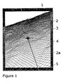
- Figure 1 shows a display surface 1 according to the invention with a perspective view 2 and a surrounding frame 3.
- the midpoint of the display surface 1 consists of a user symbol 4 that represents the aircraft of the user.
- the perspective view 2 is achieved via a grid 2a, which represents the third dimension.
- the position of the aircraft of the user is identified by a user symbol 4 at the center of the perspective view 2.
- the perspective can be changed by scaling the grid up or down. Other perspective view options relative to that of the user are of course possible.
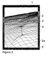
- Figure 2 shows a second perspective in which the surroundings being displayed in perspective view has been reduced by changing the viewing scale. It is also possible to utilize a larger portion of the view to provide a display in any direction relative to the aircraft.
- the perspective display provides a visualization of the position of the aircraft of the user in relation to external objects and the surroundings.
- parameters that provide additional information about the speed, altitude and direction of the aircraft of the user are also displayed.
- the frame 3 is arranged on the periphery of the perspective view 2.
- the frame 3 extends uninterrupted around the entire perspective view.
- the frame can also be interrupted so that one or more fields are created on the periphery of the perspective view. This embodiment may be relevant in connection with target tracking, when information in the direction of flight of the aircraft is of primary relevance.
- the frame is semi-transparent and partially overlaps the perspective view.
- the frame can of course also surround the perspective view without overlapping it, whereupon the frame 3 can encompass the entire view.
- the frame can be delimited from the perspective view 2 by only a contour line.
- the frame can then be made transparent.
- the frame is rectangular in the embodiments shown in figures 1 and 2 . This shape is adapted to the shape of the display so that the frame conforms to the edge of the perspective display regardless of whatever geometric shape it may have.
- the scale of the frame can be adjusted to that of the perspective view. If the selected perspective is changed, then the scale of the frame can be adjusted accordingly.
- the perspective view showed in Figure 1 mirrors more extensive geographical surroundings than is the case for the perspective view shown in Figure 2 .
- the scale of the frame in Figure 1 should then be larger than the scale used for the frame in Figure 2 .
- a number of symbols 5 are displayed in the semi-transparent frame, which symbols represent aircraft or targets located outside the field of view of the displayed perspective view.
- the positions of the symbols 5 in the frame 3 are calculated based on the rectangular shape of the frame and the angle of bearing between the object of the user and objects in the external surroundings. If a symbol 5 is located in the upper half of the frame 3, then the object is located in front of the aircraft of the user. The opposite applies if the symbol is located in the lower half of the frame 3.
- the symbols 5 are supplemented with an altitude reading that indicates the altitude in meters or thousands of meters. Information concerning range or a combination of altitude and range is also possible. However, it is important that the information be limited so that its clarity and ease of overall comprehension are not lost. In those cases where a plurality of symbols 5 are positioned near to one another, the symbols 5 for those aircraft that are most remote can be toned down so that the most proximate aircraft stand out better.
- Figure 3 shows an overlap between two symbols, 5a and 5b.
- the object at an altitude of 6000 meters is closer than the object at an altitude of 2000 meters, which means that symbol 5a is dimmed by the overlap.
- the method and device according to the invention improve the ability of the pilot to maintain his conception of the positions of other objects in relation to his own, regardless of whether or not they are visible in a perspective view, and without the need to glance at other instrumentation in order to update his knowledge concerning said objects. This enables the pilot to focus his attention, and thereby increase his awareness of the situation.
Description
- The invention concerns a method for displaying surrounding objects on a display surface. The invention also concerns a device for use in an aircraft to display objects surrounding said aircraft. Using the method and device according to the invention, a first number of objects within selected geographic surroundings is displayed in perspective on the display surface.
- Visual display systems are used to provide an operator, such as a pilot in an airplane, with information concerning what is happening in the surrounding airspace. One such display system is a perspective display, which consists of a display screen on which a perspective view of the surroundings is displayed. The perspective display is a two-dimensional representation of three-dimensional surroundings. By allowing, e.g. a grid of boxes or points to represent a third dimension on the two-dimensional display surface, a display is created in perspective. One such perspective display is known from, e.g.
US 5,257,347 , which describes a method and device for generating a perspective representation of surrounding terrain on a two-dimensional display surface. - In a known type of perspective display, objects in the external surroundings are displayed in a way that enables the pilot to form a conception as to his own position relative to external objects by viewing himself from a chosen perspective. Furthermore, objects in the external surroundings can be displayed on a basis of varying size in the field of view, which enables the pilot to obtain an overview of his flight status, or to focus on a limited part of the external surroundings.
- In a perspective display, the extent of the perspective is limited horizontally, vertically and in depth. Information about objects located outside of the range of visibility must come from other types of indicators. The limitations of the perspective display entail that the pilot must shift his attention between indicators in order to stay updated regarding his situation vis-a-vis the external surroundings. Since a pilot in a combat aircraft has a multiplicity of instruments in his field of view, this means that it must be easy for him to interpret the instrument readings on displays, and easy to convert those readings into his visualization of his surroundings and his spatial conception. Forcing a pilot to frequently shift his attention among different display types and simultaneously convert data in such an environment can result in a poor overall awareness of his external surroundings.
- The object of the invention is to provide a display system that eliminates the aforementioned problems. In the display method according to the invention, a display surface on a perspective display is used to present a first number of objects within predetermined geographical surroundings. The display is presented from a chosen perspective. Objects that are located outside of the selected geographic surroundings, but within a predetermined distance, are represented by symbols in a frame on the periphery of said display surface. The placements of the objects in this frame provide a two-dimensional representation of the actual positions of the objects.
- In a preferred embodiment of the invention, the frame is surrounding the perspective display.
- In an embodiment of the invention, the objects are displayed as symbols in the frame. These symbols can be designed so that the nearby objects are displayed most prominently.
- In a preferred embodiment of the invention, the symbols are disposed in a manner consistent with their directions, which means that symbols placed in the upper half of the frame are located in front of the object of the user, while symbols placed in the lower half are located behind said object.
- The invention also concerns a device for use in an aircraft to display objects surrounding said aircraft. The device comprises a display surface on which a perspective view of selected geographic surroundings is displayed. A frame on the periphery of the display surface represents a chosen environment outside of said geographic surroundings.
- In an embodiment of the invention, said frame is semi-transparent and superimposed over the perspective view.
- The superimposition of information provides a user-friendly display using two-dimensional information in a perspective view. The pilot thereby avoids having to shift his attention between separate screen displays, and is thus better able to maintain his conception of the positions of other objects in relation to his own, regardless of whether or not they are visible in the perspective view. This enables the pilot to focus his attention, and thereby increases his awareness of the situation.
-
- Figure 1
- Shows the display system according to the invention in a first perspective.
- Figure 2
- Shows the display system according to the invention in a second perspective.
- Figure 3
- Shows symbols for objects, and overlapping among same.
-
Figure 1 shows adisplay surface 1 according to the invention with aperspective view 2 and a surroundingframe 3. The midpoint of thedisplay surface 1 consists of auser symbol 4 that represents the aircraft of the user. - The
perspective view 2 is achieved via agrid 2a, which represents the third dimension. The position of the aircraft of the user is identified by auser symbol 4 at the center of theperspective view 2. The perspective can be changed by scaling the grid up or down. Other perspective view options relative to that of the user are of course possible.Figure 2 shows a second perspective in which the surroundings being displayed in perspective view has been reduced by changing the viewing scale. It is also possible to utilize a larger portion of the view to provide a display in any direction relative to the aircraft. - The perspective display provides a visualization of the position of the aircraft of the user in relation to external objects and the surroundings. In the embodiment shown in the figure, parameters that provide additional information about the speed, altitude and direction of the aircraft of the user are also displayed.
- The
frame 3 is arranged on the periphery of theperspective view 2. In the embodiments shown, theframe 3 extends uninterrupted around the entire perspective view. The frame can also be interrupted so that one or more fields are created on the periphery of the perspective view. This embodiment may be relevant in connection with target tracking, when information in the direction of flight of the aircraft is of primary relevance. - In the embodiments shown in
figures 1 and2 , the frame is semi-transparent and partially overlaps the perspective view. The frame can of course also surround the perspective view without overlapping it, whereupon theframe 3 can encompass the entire view. Alternatively, the frame can be delimited from theperspective view 2 by only a contour line. The frame can then be made transparent. The frame is rectangular in the embodiments shown infigures 1 and2 . This shape is adapted to the shape of the display so that the frame conforms to the edge of the perspective display regardless of whatever geometric shape it may have. - The scale of the frame can be adjusted to that of the perspective view. If the selected perspective is changed, then the scale of the frame can be adjusted accordingly. The perspective view showed in
Figure 1 mirrors more extensive geographical surroundings than is the case for the perspective view shown inFigure 2 . The scale of the frame inFigure 1 should then be larger than the scale used for the frame inFigure 2 . - A number of
symbols 5 are displayed in the semi-transparent frame, which symbols represent aircraft or targets located outside the field of view of the displayed perspective view. The positions of thesymbols 5 in theframe 3 are calculated based on the rectangular shape of the frame and the angle of bearing between the object of the user and objects in the external surroundings. If asymbol 5 is located in the upper half of theframe 3, then the object is located in front of the aircraft of the user. The opposite applies if the symbol is located in the lower half of theframe 3. - In the embodiments shown in
figures 1 and2 , thesymbols 5 are supplemented with an altitude reading that indicates the altitude in meters or thousands of meters. Information concerning range or a combination of altitude and range is also possible. However, it is important that the information be limited so that its clarity and ease of overall comprehension are not lost. In those cases where a plurality ofsymbols 5 are positioned near to one another, thesymbols 5 for those aircraft that are most remote can be toned down so that the most proximate aircraft stand out better. - When a plurality of objects or aircraft have a directional relationship within a degree of one another, the
symbol 5 for the object that is closest to the aircraft of the user is given priority. Thissymbol 5 maintains its black coloration while the other symbols are simultaneously shaded or made less prominent by some other means. This produces a better display and provides a guide as to the distance interrelationships among the aircraft.Figure 3 shows an overlap between two symbols, 5a and 5b. The object at an altitude of 6000 meters is closer than the object at an altitude of 2000 meters, which means thatsymbol 5a is dimmed by the overlap. - The method and device according to the invention improve the ability of the pilot to maintain his conception of the positions of other objects in relation to his own, regardless of whether or not they are visible in a perspective view, and without the need to glance at other instrumentation in order to update his knowledge concerning said objects. This enables the pilot to focus his attention, and thereby increase his awareness of the situation.
Claims (5)
- A method for displaying surrounding objects of an aircraft of user on a display surface (1) in said aircraft, wherein a first number of objects within selected geographic surroundings is displayed in a perspective view (2) on the display surface, characterized in that the aircraft of the user is identified by a user symbol (4) at the center of the perspective view (2), wherein a second number of objects in a selected environment outside of said geographic surroundings, but within a predetermined distance, is represented by symbols (5) in a frame (3) on the periphery of said display surface (1), the frame (3) being a representation of said selected environment, whereupon placements of the symbols (5) in the frame (3) provide a two-dimensional representation of the actual positions of the second number of objects and wherein a symbol placed in the upper half of the frame represents an object that is in front of the aircraft of the user and a symbol placed in the lower half of the frame represents an object that is located behind said aircraft.
- A method according to claim 1, characterized in that the symbols (5) are designed so that the nearest objects are displayed most prominently.
- A method according claim 1, characterized in that the symbols (5) are disposed in a manner consistent with their directions.
- A device used in an aircraft of a user to display objects surrounding said aircraft, wherein a first number of objects within selected geographic surroundings is displayed in a perspective view (2) on a display surface (1), characterized by the aircraft of the user is identified by a user symbol (4) at the center of the perspective view (2), a frame (3) on the periphery of said display surface (1), which frame (3) is a representation of a selected environment outside of said geographic surroundings, but within a predetermined distance, and symbols (5) in the frame, which symbols (5) represent a second number of objects in the selected environment, whereupon the placements of the symbols (5) in the frame (3) provide a two dimensional representation of the actual positions of the second number of objects, and wherein a symbol placed in the upper half of the frame represents an object that is in front of the aircraft of the user and a symbol placed in the lower half of the frame represents an object that is located behind said aircraft.
- A device according to claim 4, characterized in that the frame (3) being semi-transparent and superimposed over the perspective view (2).
Applications Claiming Priority (3)
| Application Number | Priority Date | Filing Date | Title |
|---|---|---|---|
| SE0102796A SE521295C2 (en) | 2001-08-22 | 2001-08-22 | Method and device for object presentation |
| SE0102796 | 2001-08-22 | ||
| PCT/SE2002/001269 WO2003019225A1 (en) | 2001-08-22 | 2002-06-26 | Method and device for displaying objects |
Publications (2)
| Publication Number | Publication Date |
|---|---|
| EP1428042A1 EP1428042A1 (en) | 2004-06-16 |
| EP1428042B1 true EP1428042B1 (en) | 2013-07-31 |
Family
ID=20285093
Family Applications (1)
| Application Number | Title | Priority Date | Filing Date |
|---|---|---|---|
| EP02744048.6A Expired - Lifetime EP1428042B1 (en) | 2001-08-22 | 2002-06-26 | Method and device for displaying objects |
Country Status (5)
| Country | Link |
|---|---|
| US (1) | US20040201589A1 (en) |
| EP (1) | EP1428042B1 (en) |
| ES (1) | ES2428525T3 (en) |
| SE (1) | SE521295C2 (en) |
| WO (1) | WO2003019225A1 (en) |
Families Citing this family (7)
| Publication number | Priority date | Publication date | Assignee | Title |
|---|---|---|---|---|
| US7471214B2 (en) * | 2005-10-13 | 2008-12-30 | Honeywell International Inc. | Intuitive wind velocity and direction presentation |
| US7908078B2 (en) | 2005-10-13 | 2011-03-15 | Honeywell International Inc. | Perspective-view visual runway awareness and advisory display |
| US7403133B2 (en) * | 2005-10-13 | 2008-07-22 | Honeywell International, Inc. | Dynamic primary flight displays for unusual attitude conditions |
| US20070085860A1 (en) * | 2005-10-13 | 2007-04-19 | Honeywell International Inc. | Technique for improving the readability of graphics on a display |
| US7432828B2 (en) | 2006-02-14 | 2008-10-07 | Honeywell International Inc. | Dynamic lateral deviation display |
| DE102007014015B4 (en) * | 2007-03-23 | 2010-07-01 | Eads Deutschland Gmbh | Human-machine interface for pilot support during takeoff and landing of a vehicle with a reduced external view |
| EP2166372B1 (en) * | 2008-09-23 | 2011-08-31 | EADS Deutschland GmbH | Human-machine interface for supporting a pilot when taking off or landing an airplane in low visibility |
Citations (2)
| Publication number | Priority date | Publication date | Assignee | Title |
|---|---|---|---|---|
| US5057835A (en) * | 1987-10-28 | 1991-10-15 | Eventide, Inc. | Map and text display system for vehicle navigation |
| US5257347A (en) * | 1986-03-07 | 1993-10-26 | Gec - Marconi Limited | Display methods and apparatus |
Family Cites Families (12)
| Publication number | Priority date | Publication date | Assignee | Title |
|---|---|---|---|---|
| US4914605A (en) * | 1984-10-22 | 1990-04-03 | Etak, Inc. | Apparatus and method for displaying a map |
| GB8620433D0 (en) * | 1986-08-22 | 1987-01-14 | Gec Avionics | Displays |
| CA2017331A1 (en) * | 1989-06-30 | 1990-12-31 | Jerry W. Huff | Three-dimensional perspective plan-view format for situation awareness displays |
| CA2018006A1 (en) * | 1989-06-30 | 1990-12-31 | William R. Hancock | Inside/out perspective format for situation awareness displays |
| US5461571A (en) * | 1992-11-17 | 1995-10-24 | Honeywell Inc. | Complementary thread display method and apparatus |
| DE4314811A1 (en) * | 1993-05-05 | 1994-12-08 | Vdo Luftfahrtgeraete Werk Gmbh | Procedure for displaying flight guidance information |
| DE69434693T2 (en) * | 1993-12-27 | 2006-08-24 | Nissan Motor Co., Ltd., Yokohama | Vehicle guidance device and method using a display unit |
| US6005581A (en) * | 1994-01-18 | 1999-12-21 | Honeywell, Inc. | Terrain elevation path manager |
| US5971580A (en) * | 1996-04-17 | 1999-10-26 | Raytheon Company | Tactical awareness monitoring and direct response system |
| US5838262A (en) * | 1996-12-19 | 1998-11-17 | Sikorsky Aircraft Corporation | Aircraft virtual image display system and method for providing a real-time perspective threat coverage display |
| US5974423A (en) * | 1998-03-09 | 1999-10-26 | Margolin; Jed | Method for converting a digital elevation database to a polygon database |
| US7487462B2 (en) * | 2002-02-21 | 2009-02-03 | Xerox Corporation | Methods and systems for indicating invisible contents of workspace |
-
2001
- 2001-08-22 SE SE0102796A patent/SE521295C2/en not_active IP Right Cessation
-
2002
- 2002-06-26 WO PCT/SE2002/001269 patent/WO2003019225A1/en not_active Application Discontinuation
- 2002-06-26 ES ES02744048T patent/ES2428525T3/en not_active Expired - Lifetime
- 2002-06-26 US US10/487,358 patent/US20040201589A1/en not_active Abandoned
- 2002-06-26 EP EP02744048.6A patent/EP1428042B1/en not_active Expired - Lifetime
Patent Citations (2)
| Publication number | Priority date | Publication date | Assignee | Title |
|---|---|---|---|---|
| US5257347A (en) * | 1986-03-07 | 1993-10-26 | Gec - Marconi Limited | Display methods and apparatus |
| US5057835A (en) * | 1987-10-28 | 1991-10-15 | Eventide, Inc. | Map and text display system for vehicle navigation |
Also Published As
| Publication number | Publication date |
|---|---|
| US20040201589A1 (en) | 2004-10-14 |
| EP1428042A1 (en) | 2004-06-16 |
| WO2003019225A1 (en) | 2003-03-06 |
| SE521295C2 (en) | 2003-10-21 |
| ES2428525T3 (en) | 2013-11-08 |
| SE0102796D0 (en) | 2001-08-22 |
| SE0102796L (en) | 2003-02-23 |
Similar Documents
| Publication | Publication Date | Title |
|---|---|---|
| KR100221712B1 (en) | Tcas view display format with horizontal trend | |
| US5227786A (en) | Inside/out perspective format for situation awareness displays | |
| US7375678B2 (en) | Displaying obstacles in perspective view | |
| US6181302B1 (en) | Marine navigation binoculars with virtual display superimposing real world image | |
| EP1074002B1 (en) | 3-dimensional intersection display for vehicle navigation system | |
| EP1495289B1 (en) | Terrain augmented 3d flight path display for flight management systems | |
| CA2629882C (en) | Methods and systems for displaying procedure information | |
| EP2107340B1 (en) | Waypoint display system | |
| US9347792B2 (en) | Systems and methods for displaying images with multi-resolution integration | |
| US5357263A (en) | Display instrument for aircraft for showing the aircraft orientation, particularly the rolling and pitching position or the flight path angle | |
| EP0330184A2 (en) | Helmet Mounted Display System | |
| EP1087210A2 (en) | Methods and apparatus for graphical display and editing of flight plans | |
| EP2610589B1 (en) | Method of displaying points of interest | |
| EP1428042B1 (en) | Method and device for displaying objects | |
| EP1881295B1 (en) | Overlaying information onto a view for electronic display | |
| US8939366B1 (en) | Targeting display system and method | |
| EP0405430B1 (en) | Air traffic display apparatus | |
| EP0411309A1 (en) | Three-dimensional perspective plan-view format for situation awareness displays | |
| EP1971826B8 (en) | Methods and systems for generating en-route visible terrain displays | |
| US20130300587A1 (en) | System and method for displaying runway approach texture objects | |
| EP1160544B1 (en) | Map display device, map display method, and computer program for use in map display device | |
| EP3910293A1 (en) | Visualization for real-time position monitoring in formation flying | |
| US9758256B1 (en) | Pilot-configurable information on a display unit | |
| ES2296650T3 (en) | PROCEDURE AND DEVICE FOR SUBMISSION OF OBJECTS IN A SURROUNDING SPACE. | |
| US20120249786A1 (en) | Display System |
Legal Events
| Date | Code | Title | Description |
|---|---|---|---|
| PUAI | Public reference made under article 153(3) epc to a published international application that has entered the european phase |
Free format text: ORIGINAL CODE: 0009012 |
|
| 17P | Request for examination filed |
Effective date: 20040322 |
|
| AK | Designated contracting states |
Kind code of ref document: A1 Designated state(s): AT BE CH CY DE DK ES FI FR GB GR IE IT LI LU MC NL PT SE TR |
|
| AX | Request for extension of the european patent |
Extension state: AL LT LV MK RO SI |
|
| 17Q | First examination report despatched |
Effective date: 20070808 |
|
| GRAP | Despatch of communication of intention to grant a patent |
Free format text: ORIGINAL CODE: EPIDOSNIGR1 |
|
| GRAS | Grant fee paid |
Free format text: ORIGINAL CODE: EPIDOSNIGR3 |
|
| GRAA | (expected) grant |
Free format text: ORIGINAL CODE: 0009210 |
|
| RIN1 | Information on inventor provided before grant (corrected) |
Inventor name: EKSTROEM, HAEKAN |
|
| AK | Designated contracting states |
Kind code of ref document: B1 Designated state(s): AT BE CH CY DE DK ES FI FR GB GR IE IT LI LU MC NL PT SE TR |
|
| REG | Reference to a national code |
Ref country code: CH Ref legal event code: EP Ref country code: GB Ref legal event code: FG4D |
|
| REG | Reference to a national code |
Ref country code: AT Ref legal event code: REF Ref document number: 624951 Country of ref document: AT Kind code of ref document: T Effective date: 20130815 |
|
| REG | Reference to a national code |
Ref country code: IE Ref legal event code: FG4D |
|
| REG | Reference to a national code |
Ref country code: DE Ref legal event code: R096 Ref document number: 60245319 Country of ref document: DE Effective date: 20130926 |
|
| REG | Reference to a national code |
Ref country code: ES Ref legal event code: FG2A Ref document number: 2428525 Country of ref document: ES Kind code of ref document: T3 Effective date: 20131108 |
|
| REG | Reference to a national code |
Ref country code: AT Ref legal event code: MK05 Ref document number: 624951 Country of ref document: AT Kind code of ref document: T Effective date: 20130731 |
|
| REG | Reference to a national code |
Ref country code: NL Ref legal event code: VDEP Effective date: 20130731 |
|
| PG25 | Lapsed in a contracting state [announced via postgrant information from national office to epo] |
Ref country code: PT Free format text: LAPSE BECAUSE OF FAILURE TO SUBMIT A TRANSLATION OF THE DESCRIPTION OR TO PAY THE FEE WITHIN THE PRESCRIBED TIME-LIMIT Effective date: 20131202 Ref country code: CY Free format text: LAPSE BECAUSE OF FAILURE TO SUBMIT A TRANSLATION OF THE DESCRIPTION OR TO PAY THE FEE WITHIN THE PRESCRIBED TIME-LIMIT Effective date: 20130703 Ref country code: AT Free format text: LAPSE BECAUSE OF FAILURE TO SUBMIT A TRANSLATION OF THE DESCRIPTION OR TO PAY THE FEE WITHIN THE PRESCRIBED TIME-LIMIT Effective date: 20130731 Ref country code: SE Free format text: LAPSE BECAUSE OF FAILURE TO SUBMIT A TRANSLATION OF THE DESCRIPTION OR TO PAY THE FEE WITHIN THE PRESCRIBED TIME-LIMIT Effective date: 20130731 Ref country code: BE Free format text: LAPSE BECAUSE OF FAILURE TO SUBMIT A TRANSLATION OF THE DESCRIPTION OR TO PAY THE FEE WITHIN THE PRESCRIBED TIME-LIMIT Effective date: 20130731 |
|
| PG25 | Lapsed in a contracting state [announced via postgrant information from national office to epo] |
Ref country code: GR Free format text: LAPSE BECAUSE OF FAILURE TO SUBMIT A TRANSLATION OF THE DESCRIPTION OR TO PAY THE FEE WITHIN THE PRESCRIBED TIME-LIMIT Effective date: 20131101 Ref country code: NL Free format text: LAPSE BECAUSE OF FAILURE TO SUBMIT A TRANSLATION OF THE DESCRIPTION OR TO PAY THE FEE WITHIN THE PRESCRIBED TIME-LIMIT Effective date: 20130731 Ref country code: FI Free format text: LAPSE BECAUSE OF FAILURE TO SUBMIT A TRANSLATION OF THE DESCRIPTION OR TO PAY THE FEE WITHIN THE PRESCRIBED TIME-LIMIT Effective date: 20130731 |
|
| PG25 | Lapsed in a contracting state [announced via postgrant information from national office to epo] |
Ref country code: CY Free format text: LAPSE BECAUSE OF FAILURE TO SUBMIT A TRANSLATION OF THE DESCRIPTION OR TO PAY THE FEE WITHIN THE PRESCRIBED TIME-LIMIT Effective date: 20130731 |
|
| PG25 | Lapsed in a contracting state [announced via postgrant information from national office to epo] |
Ref country code: DK Free format text: LAPSE BECAUSE OF FAILURE TO SUBMIT A TRANSLATION OF THE DESCRIPTION OR TO PAY THE FEE WITHIN THE PRESCRIBED TIME-LIMIT Effective date: 20130731 |
|
| PLBE | No opposition filed within time limit |
Free format text: ORIGINAL CODE: 0009261 |
|
| STAA | Information on the status of an ep patent application or granted ep patent |
Free format text: STATUS: NO OPPOSITION FILED WITHIN TIME LIMIT |
|
| 26N | No opposition filed |
Effective date: 20140502 |
|
| REG | Reference to a national code |
Ref country code: DE Ref legal event code: R097 Ref document number: 60245319 Country of ref document: DE Effective date: 20140502 |
|
| PG25 | Lapsed in a contracting state [announced via postgrant information from national office to epo] |
Ref country code: LU Free format text: LAPSE BECAUSE OF FAILURE TO SUBMIT A TRANSLATION OF THE DESCRIPTION OR TO PAY THE FEE WITHIN THE PRESCRIBED TIME-LIMIT Effective date: 20140626 Ref country code: MC Free format text: LAPSE BECAUSE OF FAILURE TO SUBMIT A TRANSLATION OF THE DESCRIPTION OR TO PAY THE FEE WITHIN THE PRESCRIBED TIME-LIMIT Effective date: 20130731 |
|
| REG | Reference to a national code |
Ref country code: CH Ref legal event code: PL |
|
| REG | Reference to a national code |
Ref country code: IE Ref legal event code: MM4A |
|
| PG25 | Lapsed in a contracting state [announced via postgrant information from national office to epo] |
Ref country code: LI Free format text: LAPSE BECAUSE OF NON-PAYMENT OF DUE FEES Effective date: 20140630 Ref country code: CH Free format text: LAPSE BECAUSE OF NON-PAYMENT OF DUE FEES Effective date: 20140630 Ref country code: IE Free format text: LAPSE BECAUSE OF NON-PAYMENT OF DUE FEES Effective date: 20140626 |
|
| REG | Reference to a national code |
Ref country code: FR Ref legal event code: PLFP Year of fee payment: 14 |
|
| PGFP | Annual fee paid to national office [announced via postgrant information from national office to epo] |
Ref country code: GB Payment date: 20150615 Year of fee payment: 14 Ref country code: ES Payment date: 20150611 Year of fee payment: 14 Ref country code: DE Payment date: 20150624 Year of fee payment: 14 |
|
| PGFP | Annual fee paid to national office [announced via postgrant information from national office to epo] |
Ref country code: IT Payment date: 20150611 Year of fee payment: 14 |
|
| PGFP | Annual fee paid to national office [announced via postgrant information from national office to epo] |
Ref country code: FR Payment date: 20150630 Year of fee payment: 14 |
|
| PG25 | Lapsed in a contracting state [announced via postgrant information from national office to epo] |
Ref country code: TR Free format text: LAPSE BECAUSE OF FAILURE TO SUBMIT A TRANSLATION OF THE DESCRIPTION OR TO PAY THE FEE WITHIN THE PRESCRIBED TIME-LIMIT Effective date: 20130731 |
|
| REG | Reference to a national code |
Ref country code: DE Ref legal event code: R119 Ref document number: 60245319 Country of ref document: DE |
|
| GBPC | Gb: european patent ceased through non-payment of renewal fee |
Effective date: 20160626 |
|
| REG | Reference to a national code |
Ref country code: FR Ref legal event code: ST Effective date: 20170228 |
|
| PG25 | Lapsed in a contracting state [announced via postgrant information from national office to epo] |
Ref country code: FR Free format text: LAPSE BECAUSE OF NON-PAYMENT OF DUE FEES Effective date: 20160630 Ref country code: DE Free format text: LAPSE BECAUSE OF NON-PAYMENT OF DUE FEES Effective date: 20170103 |
|
| PG25 | Lapsed in a contracting state [announced via postgrant information from national office to epo] |
Ref country code: GB Free format text: LAPSE BECAUSE OF NON-PAYMENT OF DUE FEES Effective date: 20160626 |
|
| PG25 | Lapsed in a contracting state [announced via postgrant information from national office to epo] |
Ref country code: IT Free format text: LAPSE BECAUSE OF NON-PAYMENT OF DUE FEES Effective date: 20160626 |
|
| PG25 | Lapsed in a contracting state [announced via postgrant information from national office to epo] |
Ref country code: ES Free format text: LAPSE BECAUSE OF NON-PAYMENT OF DUE FEES Effective date: 20160627 |
|
| REG | Reference to a national code |
Ref country code: ES Ref legal event code: FD2A Effective date: 20181130 |