EP1427919B1 - Muffler shell filling process and muffler filled with fibrous material - Google Patents
Muffler shell filling process and muffler filled with fibrous material Download PDFInfo
- Publication number
- EP1427919B1 EP1427919B1 EP02767481A EP02767481A EP1427919B1 EP 1427919 B1 EP1427919 B1 EP 1427919B1 EP 02767481 A EP02767481 A EP 02767481A EP 02767481 A EP02767481 A EP 02767481A EP 1427919 B1 EP1427919 B1 EP 1427919B1
- Authority
- EP
- European Patent Office
- Prior art keywords
- muffler
- internal structure
- bag
- open area
- fibrous material
- Prior art date
- Legal status (The legal status is an assumption and is not a legal conclusion. Google has not performed a legal analysis and makes no representation as to the accuracy of the status listed.)
- Expired - Lifetime
Links
Images




Classifications
-
- F—MECHANICAL ENGINEERING; LIGHTING; HEATING; WEAPONS; BLASTING
- F01—MACHINES OR ENGINES IN GENERAL; ENGINE PLANTS IN GENERAL; STEAM ENGINES
- F01N—GAS-FLOW SILENCERS OR EXHAUST APPARATUS FOR MACHINES OR ENGINES IN GENERAL; GAS-FLOW SILENCERS OR EXHAUST APPARATUS FOR INTERNAL-COMBUSTION ENGINES
- F01N13/00—Exhaust or silencing apparatus characterised by constructional features
- F01N13/18—Construction facilitating manufacture, assembly, or disassembly
-
- F—MECHANICAL ENGINEERING; LIGHTING; HEATING; WEAPONS; BLASTING
- F01—MACHINES OR ENGINES IN GENERAL; ENGINE PLANTS IN GENERAL; STEAM ENGINES
- F01N—GAS-FLOW SILENCERS OR EXHAUST APPARATUS FOR MACHINES OR ENGINES IN GENERAL; GAS-FLOW SILENCERS OR EXHAUST APPARATUS FOR INTERNAL-COMBUSTION ENGINES
- F01N1/00—Silencing apparatus characterised by method of silencing
- F01N1/02—Silencing apparatus characterised by method of silencing by using resonance
- F01N1/04—Silencing apparatus characterised by method of silencing by using resonance having sound-absorbing materials in resonance chambers
-
- F—MECHANICAL ENGINEERING; LIGHTING; HEATING; WEAPONS; BLASTING
- F01—MACHINES OR ENGINES IN GENERAL; ENGINE PLANTS IN GENERAL; STEAM ENGINES
- F01N—GAS-FLOW SILENCERS OR EXHAUST APPARATUS FOR MACHINES OR ENGINES IN GENERAL; GAS-FLOW SILENCERS OR EXHAUST APPARATUS FOR INTERNAL-COMBUSTION ENGINES
- F01N1/00—Silencing apparatus characterised by method of silencing
- F01N1/24—Silencing apparatus characterised by method of silencing by using sound-absorbing materials
-
- F—MECHANICAL ENGINEERING; LIGHTING; HEATING; WEAPONS; BLASTING
- F01—MACHINES OR ENGINES IN GENERAL; ENGINE PLANTS IN GENERAL; STEAM ENGINES
- F01N—GAS-FLOW SILENCERS OR EXHAUST APPARATUS FOR MACHINES OR ENGINES IN GENERAL; GAS-FLOW SILENCERS OR EXHAUST APPARATUS FOR INTERNAL-COMBUSTION ENGINES
- F01N2450/00—Methods or apparatus for fitting, inserting or repairing different elements
- F01N2450/06—Inserting sound absorbing material into a chamber
Definitions
- This invention relates to a process for filling a muffler shell with fibrous material, and a muffler shell filled with fibrous material.
- U.S. Patent No. 4,569,471 to Ingemansson et al. describes a process and apparatus for feeding lengths of a continuous glass fiber strand into a muffler outer shell.
- the apparatus includes a texturizing device with a nozzle for expanding the fiber strand into a wool-like material before the material enters the outer shell.
- filling of an outer cylinder 14 of the muffler shell occurs without an end-piece joined to the outer cylinder 14.
- the outer cylinder 14 is moved to a separate station where the end piece is welded onto the outer cylinder 14.
- a second embodiment illustrated in Fig.
- a perforated pipe/outer end piece assembly is located only part way in the muffler outer cylinder 14 during the glass material filling operation. After the filling operation has been completed, the perforated pipe/end piece assembly is moved to its final position within the outer cylinder 14.
- the '471 patent process is typically not used with clam shell mufflers comprising first and second halves which, when coupled together and enclosing a perforated pipe, may not have an open end through which fibrous material may be fed.
- preforms from glass material which are adapted to be inserted into a first muffler shell section prior to it being coupled to a corresponding second shell section; see U.S. Patent No. 5,766,541, the disclosure of which is incorporated herein by reference. While such preforms are acceptable in performance, they add additional cost to the muffler due to the manufacturing steps necessary to form the preforms.
- a process for filling a muffler shell with fibrous material comprises the steps of:
- the partial vacuum may be drawn prior to or at about the same time as the occurrence of the positioning step.
- the partial vacuum may also be drawn subsequent to the positioning step.
- the muffler shell may comprise first and second muffler shell outer parts.
- the process may further comprise the steps of: placing the internal structure in the first muffler shell outer part subsequent to the positioning step and while the partial vacuum is being drawn through the internal structure; placing the second muffler shell outer part adjacent to the first muffler shell outer part while the partial vacuum is still being drawn through the internal structure such that the first and second muffler shell parts define an internal cavity containing the internal structure, and the fibrous material-filled bag; and joining the first and second muffler shell parts to one another.
- the process may further comprise the steps of: placing the internal structure in the first muffler shell outer part prior to the positioning step; placing the second muffler shell outer part adjacent to the first muffler shell outer part subsequent to the positioning step such that the first and second muffler shell parts define an internal cavity containing the internal structure, and the fibrous material-filled bag; and joining the first and second muffler shell parts to one another.
- the fibrous material in the bag may comprise a mineral fiber wool-type product.
- the step of drawing a partial vacuum through the internal structure may comprise the step of connecting a vacuum source to the internal structure.
- the bag may be formed from paper, cardboard, fiberglass, a polymeric material or any other suitable material.
- the internal structure may comprise at least one perforated element such as a perforated pipe.
- the first side total open area may comprise between about 1 % and about 60% of the total surface area of the first side of the bag and the second side total open area may comprise between about 0% and about 4% of the total surface area of the second side of the bag. Accordingly, between about 40% and about 99% of the total surface area of the first side of the bag comprises a solid, non-open area and is defined by the material from which the bag is formed and between about 96% and about 100% of the total surface area of the second side of the bag comprises a solid, non-open area and is defined by the bag material.
- the "total surface area" of the first side of the bag includes open and non-open areas and the "total surface area" of the second side of the bag includes open and non-open areas.
- the muffler shell may alternatively comprise a generally cylindrical main shell portion and opposing end caps.
- One of the end caps may be integral with the main shell portion or the internal structure, while the other end cap is adapted to be coupled such as by welding or crimping to the cylindrical main shell portion.
- both end caps may be formed as separate parts from the main shell portion.
- the method may further comprise the step of placing the internal structure in the generally cylindrical main shell portion subsequent to the positioning step and while the partial vacuum is being drawn through the internal structure.
- a muffler comprising a muffler shell including one or more muffler shell outer parts which define an internal cavity; an internal structure adapted to extend at least part way through the shell internal cavity and having one or more openings communicating with the shell internal cavity; and a fibrous-filled bag positioned in the internal cavity, the bag having a first side with one or more first perforations defining a first side total open area and a second side with either no perforations or one or more second perforations defining a second side total open area, the first open area being greater than the second open area.
- the internal structure may comprise at least one perforated element.
- the fibrous material may comprise a mineral fiber wool-type product.
- the first side total open area may comprise between about 1 % to about 60% of the first side of the bag and all ranges subsumed therein and the second side total open area may comprise between about 0% to about 4% of the second side of the bag, all ranges subsumed therein, and preferably between about 0% to about 0.5% of the second side of the bag.
- Advantages associated with the present invention include: improved bag placement within the internal cavity due to the creation of a partial vacuum in the internal structure; reduction in time required to fill a muffler shell with fibrous material; muffler shell filling may occur without tape to maintain a fibrous material-filled bag in position within the muffler shell or a texturizing device if the bags to be placed within the muffler shell have been previously filled with fibrous material; improved muffler acoustic attenuation properties due to proper location and compaction of the fibrous material around and against the internal structure.
- a process is provided for filling mufflers with fibrous material via fibrous material-filled bags.
- Mufflers filled in accordance with the present invention are capable of being incorporated into vehicle exhaust systems and function as acoustic attenuators.
- Fig. 9 illustrates a first clam shell type muffler 10 filled with fibrous material in accordance with a process of a first embodiment of the present invention.
- the muffler 10 comprises an outer shell 12 formed from first and second muffler shell outer parts 14 and 16.
- the first and second parts 14 and 16 define an internal cavity 17, see Fig. 6, when coupled together.
- An internal structure 18 is provided in the shell internal cavity 17, see Figs. 3-6.
- the structure 18 comprises a generally U-shaped perforated pipe 20, an inlet pipe 22 integral with the perforated pipe 20 so as to communicate with the pipe 20, and first and second partitions 24 and 26.
- the partitions 24 and 26 define first, second and third compartments 30a-30c within the internal cavity 17, see Fig.
- first, second and third fibrous material-filled bags 40a-40c are positioned about the internal structure 18 so as to be provided respectfully in the first, second and third compartments 30a-30c, see Figs. 5 and 6.
- a first exhaust pipe (not shown) extending between a vehicle engine and the muffler 10 is coupled to the inlet pipe 22.
- a second exhaust pipe (not shown) is coupled to an exit portion 20a of the perforated pipe 20.
- exhaust gases pass into the muffler via the first exhaust pipe. Acoustic energy generated by those gases passes through and from the perforated pipe 20 to the fibrous material which functions to dissipate a portion of that acoustic energy.
- the first and second muffler shell outer parts 14 and 16 may be formed having any conventional and suitable shape.
- the internal structure 18 may comprise one or more perforated pipes; one or more non-perforated pipes coupled to one or more perforated pipes; or one or more perforated elements, such as a triangular, rectangular or other geometric-shaped element coupled to one or more perforated or non-perforated pipes. It is also contemplated that the internal structure 18 may include 0, 1 or 3 or more partitions.
- a vacuum hose 50 is coupled to a vacuum source 52a and the exit portion 20a of the perforated pipe 20.
- the vacuum source 52a When the vacuum source 52a is activated, it functions to pull air through perforations 20b provided in the pipe 20 via hose 50. A partial vacuum is then created within and surrounding the pipe 20.
- a plug 52 is provided in the inlet pipe 22 so as to prevent air from being drawn in through the pipe 22 and increase the quantity of air being drawn in through the pipe 20 during the fibrous material filling operation.
- the fibrous material-filled bags 40a-40c are then positioned about the pipe 20, either manually or via an apparatus (not shown).
- the bags 40a-40c are located about the pipe 20 such that when the internal structure 18 and the bags 40a-40c are positioned within the internal cavity 17, the first, second and third bags 40a-40c fill the first, second and third internal cavity compartments 30a-30c, respectively, see Figs. 4-6.
- the vacuum source 52a is activated before initiation of the positioning step.
- the vacuum source 52a may be initiated at about the same time as or subsequent to the occurrence of the positioning step.
- the bags 40a-40c are constructed from the same material and in the same manner. However, they do differ in size so as to conform to the size of the internal cavity compartments 30a-30c. Hence, a description of bag 40b, illustrated in Figs. 1 and 2, set out below is also applicable to the construction and make-up of bags 40a and 40c.
- the bag 40b is formed from paper, a polymeric material, cardboard, fiberglass or any other suitable material. It comprises first and second sides 42a and 42b.
- the first side 42a of the bag 40b is provided with a plurality of first perforations 44a.
- the open areas defined by those perforations 44a, when summed together, define a first side total open area 45a in the bag first side 42a.
- the bag second side 42b is provided with no perforations, see Fig. 1.
- the bag second side 42b may comprise one or more second perforations.
- the open areas defined by those second perforations, when summed together, define a second side total open area in the bag second side 42b.
- the first side total open area 45a is greater than the second side total open area.
- the first side total open area 45a may comprise between about 1 % and 60% of the total surface area of the bag first side 42a while the second side total open area may comprise between about 0% and about 4% of the total surface area of the bag second side 42b.
- between about 40% and about 99% of the total surface area of the first side 42a of the bag 40b comprises a solid, non-open area 45b and is defined by the material from which the bag 40b is formed and between about 96% and 100% of the total surface area of the second side 42b of the bag 40b comprises a solid, non-open area 45c and is defined by the bag material.
- Each bag 40a-40c is preferably filled with fibrous material 60.
- a conventional texturizing device (not shown) may be used to fill the bags 40a-40c by placing a nozzle of the device in an opening located in a corner or edge of each bag.
- Conventional texturizing devices are disclosed in U.S. Patent Nos. 4,569,471 and 5,976,453, the disclosures of which are incorporated herein by reference. After the filling operation, the bag openings are sealed or otherwise closed.
- the fibrous material 60 may be formed from one or more continuous glass filament strands, wherein each strand comprises a plurality of filaments.
- the filaments may be formed from E-glass or S-glass, or other glass compositions.
- the continuous strand material may comprise an E-glass roving sold by Owens Corning under the trademark ADVANTEX® or an S-glass roving sold by Owens Corning under the trademark Zen Tron® . It is also contemplated that ceramic fibrous material or other mineral fibrous material may be used instead of glass fibrous material.
- each bag 40a-40c may be filled with a sufficient quantity of fibrous material 60 such that each corresponding internal cavity compartment 30a-30c is provided with between about 90-200 grams/liter of fibrous material 60. It is noted that during the initial operation of the vehicle to which the muffler 10 is assembled, the heated gases may burn or otherwise destroy the material from which each bag 40a-40c is formed such that only the fibrous material 60 remains in the shell internal cavity 17.
- the vacuum source 52a be activated during the step of positioning the bags 40a-40c about the internal structure 18.
- the bags 40a-40c are positioned relative to the internal structure 18 such that the first side 42a of each bag 40a-40c faces the internal structure 18 while the second side 42b faces away from the internal structure 18. Because each of the bags 40a-40c is so positioned, has perforations 44a in the bag first side 42a, and either no perforations or only a limited total open area in the bag second side 42b, the partial vacuum created in the perforated pipe 20 causes the fibrous material-filled bags 40a-40c to be drawn inwardly towards and compacted against the pipe 20 during the positioning operation.
- the bags 40a-40c and the internal structure 18 are positioned within the first muffler shell outer part 14, see Fig. 6.
- This step preferably occurs with the vacuum source 52a activated. If any portion of a bag 40a-40c extends beyond an outer edge 14a of the first muffler shell outer part 14, that bag portion is repositioned so that it resides entirely within the outer edge 14a of the first part 14.
- the second muffler shell outer part 16 is placed onto the first muffler shell outer part 14, see Fig. 7, which step preferably occurs with the vacuum source 52a activated, and joined to the first part 14 via a conventional welding operation or crimping operation, see Fig. 8.
- the vacuum source 52a may be deactivated and the plug 52 removed prior to the crimping operation.
- Fig. 17 illustrates a second clam shell type muffler 100 filled with fibrous material in accordance with a process of a second embodiment of the present invention.
- the muffler 100 comprises an outer shell 120 formed from first and second muffler shell outer parts 140 and 160.
- the first and second parts 140 and 160 define an internal cavity 170, see Fig. 14, when coupled together.
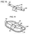
- An internal structure 180 is provided in the shell internal cavity 170, see Figs. 11-14.
- the structure 180 comprises a perforated pipe 200 and a partition 240.
- the partition 240 defines first and second compartments 300a and 300b within the internal cavity 170 and may be perforated so as to permit gases to pass between the compartments 300a-300b.
- first and second fibrous material-filled bags 400a and 400b are positioned about the internal structure 180 so as to be provided respectfully in the first and second compartments 300a and 300b, see Fig. 14.
- a first exhaust pipe (not shown) extending between a vehicle engine and the muffler 100 is coupled to an entrance portion 202 of the pipe 200.
- a second exhaust pipe (not shown) is coupled to an exit portion 204 of the perforated pipe 200.
- the first and second muffler shell outer parts 140 and 160 may be formed having any conventional and suitable shape.
- the internal structure 180 may comprise two or more perforated pipes; one or more non-perforated pipes coupled to one or more perforated pipes; or one or more perforated elements, such as a triangular, rectangular or other geometric-shaped element coupled to one or more perforated or non-perforated pipes. It is also contemplated that the internal structure 180 may include 0 or 2 or more partitions.
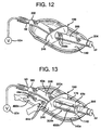
- a vacuum hose 50 is coupled to a vacuum source 52a and the entrance portion 202 of the perforated pipe 200, see Fig. 12.
- the vacuum source 52a When the vacuum source 52a is activated, it functions to pull air through perforations 200b provided in the pipe 200 via hose 50. A partial vacuum is then created within and surrounding the pipe 200.
- a plug 52 is provided in the exit portion 204 of the pipe 200 so as to prevent air from being drawn in through the pipe exit portion 204 and to increase the quantity of air being drawn in through perforations 200b in the pipe 200 during the fibrous material filling operation.
- the fibrous material-filled bags 400a and 400b are then positioned about the pipe 200, either manually or via an apparatus (not shown), see Figs 13 and 14.
- bag 400a is positioned about the pipe 200 prior to the bag 400b being positioned about the pipe 200 to take advantage of the increased level of vacuum in the section of the pipe 200 receiving bag 400a as that pipe section is nearest to the vacuum source 52a.
- the bags 400a and 400b are separated from one another by the partition 240 so as to be positioned in and fill the compartments 300a and 300b.
- the vacuum source 52a is activated before initiation of the positioning step. However, the vacuum source 52a may be initiated at about the same time as or subsequent to the occurrence of the positioning step.
- the bags 400a and 400b are constructed from the same material and have the same features as bags 40a-40c described above. Further, the bags 400a and 400b are filled with the same fibrous material 60 as the bags 40a-40c. Hence, the description of bags 40a-40c and fibrous material 60 is also applicable to the construction and make-up of bags 400a and 400b and the fibrous material provided therein.
- the bags 400a and 400b are positioned such that the first side 42a, i.e., the side having perforations 44a, of each bag 400a and 400b faces the internal structure 180 while the second side 42b faces away from the internal structure 180. Because each of the bags 400a and 400b is so positioned, has perforations 44a in the bag first side 42a, and either no perforations or a limited number of perforations in the bag second side 42b, the partial vacuum created in the perforated pipe 200 causes the fibrous material-filled bags 400a and 400b to be drawn inwardly towards and compacted against the pipe 200 during the positioning operation.
- any portion of a bag 400a and 400b extends beyond an outer edge 140a of the first muffler shell outer part 140, that bag portion is repositioned so that it resides entirely within the outer edge 140a of the first part 140.
- the second muffler shell outer part 160 is placed onto the first muffler shell outer part 140, see Fig. 15, and joined to the first part 140 via a conventional welding operation or crimping operation, see Fig. 16.
- the vacuum source 52a may be deactivated and the plug 52 removed prior to the crimping operation.
- Fig. 21 illustrates a non-clam shell type muffler 500 filled with fibrous material in accordance with a process of a third embodiment of the present invention.
- the muffler 500 comprises a generally cylindrical main shell portion 502 which defines an internal cavity 570, see Fig. 18.
- An internal structure 580 is provided in the shell internal cavity 570.
- the structure 580 comprises a perforated pipe 582 and a partition 584.
- the partition 584 defines first and second compartments 590a and 590b within the internal cavity 570 and may be perforated so as to permit gases to pass between the compartments 590a and 590b.
- first and second fibrous material-filled bags 600a and 600b are positioned about the internal structure 580 so as to be provided respectfully in the first and second compartments 590a and 590b, see Fig. 19.
- a first exhaust pipe (not shown) extending between a vehicle engine and the muffler 500 is coupled to an entrance portion 582a of the pipe 582.
- a second exhaust pipe (not shown) is coupled to an exit portion 582b of the perforated pipe 582.
- exhaust gases pass into the muffler 500 via the first exhaust pipe. Acoustic energy generated by those gases passes through and from the perforated pipe 582 to the fibrous material which functions to dissipate a portion of that acoustic energy.
- the main shell portion 502 may be formed having any conventional and suitable shape.
- the internal structure 580 may comprise two or more perforated pipes; one or more non-perforated pipes coupled to one or more perforated pipes; or one or more perforated elements, such as a triangular, rectangular or other geometric-shaped element coupled to one or more perforated or non-perforated pipes. It is also contemplated that the internal structure 580 may include 0 or 2 or more partitions.
- a vacuum hose 50 is coupled to a vacuum source 52a and the entrance portion 582a of the perforated pipe 582, see Fig. 19.
- the vacuum source 52a When the vacuum source 52a is activated, it functions to pull air through perforations 582c provided in the pipe 582 via hose 50. A partial vacuum is then created within and surrounding the pipe 582.
- a plug (not shown) may be provided in the exit portion 582b of the pipe 582 so as to prevent air from being drawn in through the exit portion 582b and to increase the quantity of air being drawn in through perforations 582c in the pipe 582 during the fibrous material filling operation.
- the fibrous material-filled bags 600a and 600b are then positioned about the pipe 582, either manually or via an apparatus (not shown), see Fig 19.
- the bags 600a and 600b are separated from one another by the partition 584 so as to fill the compartments 590a and 590b.
- the vacuum source 52a is activated before initiation of the positioning step.
- the vacuum source 52a may be initiated at about the same time as or subsequent to the occurrence of the positioning step.
- the bags 600a and 600b are constructed from the same material and in the same manner as bags 40a-40c described above. Further, the bags 600a and 600b are filled with the same fibrous material 60 as the bags 40a-40c. Hence, the description of bags 40a-40c and fibrous material 60 is also applicable to the construction and make-up of bags 600a and 600b.
- the bags 600a and 600b are positioned such that their first sides, i.e., the sides having perforations, face the internal structure 580 while the second sides face away from the internal structure 580. Because each of the bags 600a and 600b is so positioned, has perforations in the bag first side, and either no perforations or only a limited total open area in the bag second side, the partial vacuum created in the perforated pipe 582 causes the fibrous material-filled bags 600a and 600b to be drawn inwardly towards and compacted against the pipe 582.
- the bags 600a and 600b After the bags 600a and 600b have been positioned about the perforated pipe 582 and drawn inwardly toward the pipe 582 via the partial vacuum created in the pipe 582, the bags 600a and 600b and the internal structure 580 are positioned within the main shell portion 502. Thereafter, a first end cap 586 and a second end cap 588 are positioned over the entrance and exit portions 582a and 582b of the pipe 582, abutted against first and second outer edges 502a and 502b of the main portion 502 and coupled to the main portion 502 via a conventional welding operation or crimping operation, see Fig. 21.
- the vacuum source 52a may be deactivated and the plug removed prior to the crimping operation.
- fibrous material-filled bags may be positioned about internal structure 18 in the Fig. 6 embodiment and only one fibrous material-filled bag may be positioned about internal structure 180 in the Fig. 13 embodiment or internal structure 580 in the Fig. 19 embodiment.
Landscapes
- Engineering & Computer Science (AREA)
- Chemical & Material Sciences (AREA)
- Combustion & Propulsion (AREA)
- Mechanical Engineering (AREA)
- General Engineering & Computer Science (AREA)
- Exhaust Silencers (AREA)
Abstract
Description
- This invention relates to a process for filling a muffler shell with fibrous material, and a muffler shell filled with fibrous material.
- U.S. Patent No. 4,569,471 to Ingemansson et al. describes a process and apparatus for feeding lengths of a continuous glass fiber strand into a muffler outer shell. The apparatus includes a texturizing device with a nozzle for expanding the fiber strand into a wool-like material before the material enters the outer shell. In a first embodiment, filling of an
outer cylinder 14 of the muffler shell occurs without an end-piece joined to theouter cylinder 14. After the filling operation is completed, theouter cylinder 14 is moved to a separate station where the end piece is welded onto theouter cylinder 14. In a second embodiment, illustrated in Fig. 3, a perforated pipe/outer end piece assembly is located only part way in the mufflerouter cylinder 14 during the glass material filling operation. After the filling operation has been completed, the perforated pipe/end piece assembly is moved to its final position within theouter cylinder 14. - The '471 patent process is typically not used with clam shell mufflers comprising first and second halves which, when coupled together and enclosing a perforated pipe, may not have an open end through which fibrous material may be fed.
- It is also known in the prior art to form preforms from glass material which are adapted to be inserted into a first muffler shell section prior to it being coupled to a corresponding second shell section; see U.S. Patent No. 5,766,541, the disclosure of which is incorporated herein by reference. While such preforms are acceptable in performance, they add additional cost to the muffler due to the manufacturing steps necessary to form the preforms.
- It is also known to fill bags or a mesh with fibrous material. The filled bag or mesh is then inserted into a first muffler shell section prior to the first shell section being coupled to a second shell section, see U.S. Patent No. 6,068,082, the disclosure of which is incorporated herein by reference. However, assembly of such mufflers is oftentimes difficult and time consuming due to the expanded nature of the filled bag and limited volume within the muffler shell outer parts. It is noted that any fibrous material extending out beyond the outer edges of the first and second muffler shell outer parts may have a detrimental impact on a weld at that point, i.e., may cause a void in the weld, and exposed fibers are aesthetically undesirable.
- Hence, there is a need for an improved, low-cost muffler outer shell filling process which can be used to fill muffler shells.
- In accordance with a first aspect of the present invention, a process is provided for filling a muffler shell with fibrous material. The process comprises the steps of:
- providing a muffler shell comprising one or more muffler shell outer parts which define an internal cavity and an internal structure adapted to extend at least part way through the shell internal cavity and having one or more openings adapted to communicate with the shell internal cavity; providing a bag filled with fibrous material, the bag having a first side with one or more first perforations defining a first side total open area and a second side with either no perforations or one or more second perforations defining a second side total open area, the first open area being greater than the second open area; positioning the fibrous material-filled bag adjacent the internal structure such that the first side is nearest to the internal structure; and drawing a partial vacuum through the internal structure, the partial vacuum drawing the fibrous-filled bag inwardly towards the internal structure.
-
- The partial vacuum may be drawn prior to or at about the same time as the occurrence of the positioning step. The partial vacuum may also be drawn subsequent to the positioning step.
- The muffler shell may comprise first and second muffler shell outer parts. The process may further comprise the steps of: placing the internal structure in the first muffler shell outer part subsequent to the positioning step and while the partial vacuum is being drawn through the internal structure; placing the second muffler shell outer part adjacent to the first muffler shell outer part while the partial vacuum is still being drawn through the internal structure such that the first and second muffler shell parts define an internal cavity containing the internal structure, and the fibrous material-filled bag; and joining the first and second muffler shell parts to one another. Alternatively, the process may further comprise the steps of: placing the internal structure in the first muffler shell outer part prior to the positioning step; placing the second muffler shell outer part adjacent to the first muffler shell outer part subsequent to the positioning step such that the first and second muffler shell parts define an internal cavity containing the internal structure, and the fibrous material-filled bag; and joining the first and second muffler shell parts to one another.
- The fibrous material in the bag may comprise a mineral fiber wool-type product.
- The step of drawing a partial vacuum through the internal structure may comprise the step of connecting a vacuum source to the internal structure.
- The bag may be formed from paper, cardboard, fiberglass, a polymeric material or any other suitable material.
- The internal structure may comprise at least one perforated element such as a perforated pipe.
- The first side total open area may comprise between about 1 % and about 60% of the total surface area of the first side of the bag and the second side total open area may comprise between about 0% and about 4% of the total surface area of the second side of the bag. Accordingly, between about 40% and about 99% of the total surface area of the first side of the bag comprises a solid, non-open area and is defined by the material from which the bag is formed and between about 96% and about 100% of the total surface area of the second side of the bag comprises a solid, non-open area and is defined by the bag material. Hence, the "total surface area" of the first side of the bag includes open and non-open areas and the "total surface area" of the second side of the bag includes open and non-open areas.
- The muffler shell may alternatively comprise a generally cylindrical main shell portion and opposing end caps. One of the end caps may be integral with the main shell portion or the internal structure, while the other end cap is adapted to be coupled such as by welding or crimping to the cylindrical main shell portion. Alternatively, both end caps may be formed as separate parts from the main shell portion. The method may further comprise the step of placing the internal structure in the generally cylindrical main shell portion subsequent to the positioning step and while the partial vacuum is being drawn through the internal structure.
- In accordance with a second aspect of the present invention, a muffler is provided comprising a muffler shell including one or more muffler shell outer parts which define an internal cavity; an internal structure adapted to extend at least part way through the shell internal cavity and having one or more openings communicating with the shell internal cavity; and a fibrous-filled bag positioned in the internal cavity, the bag having a first side with one or more first perforations defining a first side total open area and a second side with either no perforations or one or more second perforations defining a second side total open area, the first open area being greater than the second open area.
- The internal structure may comprise at least one perforated element.
- The fibrous material may comprise a mineral fiber wool-type product.
- The first side total open area may comprise between about 1 % to about 60% of the first side of the bag and all ranges subsumed therein and the second side total open area may comprise between about 0% to about 4% of the second side of the bag, all ranges subsumed therein, and preferably between about 0% to about 0.5% of the second side of the bag.
- Advantages associated with the present invention include: improved bag placement within the internal cavity due to the creation of a partial vacuum in the internal structure; reduction in time required to fill a muffler shell with fibrous material; muffler shell filling may occur without tape to maintain a fibrous material-filled bag in position within the muffler shell or a texturizing device if the bags to be placed within the muffler shell have been previously filled with fibrous material; improved muffler acoustic attenuation properties due to proper location and compaction of the fibrous material around and against the internal structure.
-
- Fig. 1 is a perspective view of a non-perforated second side of a fibrous-filled bag used in a muffler filling process of the present invention;
- Fig. 2 is a perspective view a perforated first side of a fibrous-filled bag used in a muffler filling process of the present invention;
- Fig. 3 is a perspective view of an internal structure forming part of a first muffler filled in accordance with a filling process of the present invention;
- Fig. 4 is a perspective view illustrating a fibrous material-filled bag positioning step;
- Fig. 5 is a perspective view illustrating three separate bags positioned about the internal structure of the first muffler;
- Fig. 6 is a perspective view illustrating the step of placing the internal structure/fibrous material-filled bag assembly of Fig. 5 into a first muffler shell outer part;
- Fig. 7 is a perspective view illustrating a second muffler shell outer part positioned over the first muffler shell outer part containing the internal structure/fibrous material-filled bag assembly;
- Fig. 8 is a perspective view illustrating a crimping operation to couple the first and second muffler shell outer parts to one another;
- Fig. 9 is a view of the completed first muffler containing an internal structure/fibrous material-filled bag assembly;
- Fig. 10 is a perspective view of an internal structure forming part of a second muffler filled in accordance with a filling process of the present invention;
- Fig. 11 is a perspective view illustrating the internal structure of Fig. 10 positioned in a first muffler shell outer part of the second muffler;
- Fig. 12 is a perspective view similar to Fig. 11 illustrating a vacuum source coupled to the internal structure for drawing a partial vacuum through the internal structure;
- Figs. 13 and 14 are perspective views illustrating the step of positioning first and second fibrous material-filled bags about the internal structure of the second muffler;
- Fig. 15 is a perspective view illustrating a second muffler shell outer part positioned over the first muffler shell outer part containing the internal structure/fibrous material-filled bag assembly;
- Fig. 16 is a perspective view illustrating a crimping operation to couple the first and second muffler shell outer parts to one another;
- Fig. 17 is a view of the completed second muffler containing an internal structure/fibrous material-filled bag assembly;
- Fig. 18 is a perspective, exploded view of a third muffler;
- Fig. 19 is a view illustrating first and second fibrous material-filled bags positioned about an internal structure of the muffler illustrated in Fig. 18;
- Fig. 20 is a view showing the internal structure/fibrous material-filled bag assembly positioned within a generally cylindrical main shell portion of a muffler housing; and
- Fig. 21 is a view illustrating a crimping operation to couple an end cap to the main shell portion.
-
- A process is provided for filling mufflers with fibrous material via fibrous material-filled bags. Mufflers filled in accordance with the present invention are capable of being incorporated into vehicle exhaust systems and function as acoustic attenuators.
- Fig. 9 illustrates a first clam
shell type muffler 10 filled with fibrous material in accordance with a process of a first embodiment of the present invention. Themuffler 10 comprises anouter shell 12 formed from first and second muffler shellouter parts second parts internal cavity 17, see Fig. 6, when coupled together. Aninternal structure 18 is provided in the shellinternal cavity 17, see Figs. 3-6. In the illustrated embodiment, thestructure 18 comprises a generally U-shapedperforated pipe 20, aninlet pipe 22 integral with theperforated pipe 20 so as to communicate with thepipe 20, and first andsecond partitions partitions third compartments 30a-30c within theinternal cavity 17, see Fig. 6, and may be perforated so as to permit gases to pass between thecompartments 30a-30c. As will be discussed further below, first, second and third fibrous material-filledbags 40a-40c are positioned about theinternal structure 18 so as to be provided respectfully in the first, second andthird compartments 30a-30c, see Figs. 5 and 6. - A first exhaust pipe (not shown) extending between a vehicle engine and the
muffler 10 is coupled to theinlet pipe 22. A second exhaust pipe (not shown) is coupled to anexit portion 20a of theperforated pipe 20. During operation of a vehicle to which themuffler 10 is attached, exhaust gases pass into the muffler via the first exhaust pipe. Acoustic energy generated by those gases passes through and from theperforated pipe 20 to the fibrous material which functions to dissipate a portion of that acoustic energy. - The first and second muffler shell
outer parts internal structure 18 may comprise one or more perforated pipes; one or more non-perforated pipes coupled to one or more perforated pipes; or one or more perforated elements, such as a triangular, rectangular or other geometric-shaped element coupled to one or more perforated or non-perforated pipes. It is also contemplated that theinternal structure 18 may include 0, 1 or 3 or more partitions. - A process for incorporating the
internal structure 18 and the fibrous material-filledbags 40a-40c into themuffler shell 12 will now be described. - Initially, a
vacuum hose 50 is coupled to avacuum source 52a and theexit portion 20a of theperforated pipe 20. When thevacuum source 52a is activated, it functions to pull air throughperforations 20b provided in thepipe 20 viahose 50. A partial vacuum is then created within and surrounding thepipe 20. Aplug 52 is provided in theinlet pipe 22 so as to prevent air from being drawn in through thepipe 22 and increase the quantity of air being drawn in through thepipe 20 during the fibrous material filling operation. - The fibrous material-filled
bags 40a-40c are then positioned about thepipe 20, either manually or via an apparatus (not shown). Thebags 40a-40c are located about thepipe 20 such that when theinternal structure 18 and thebags 40a-40c are positioned within theinternal cavity 17, the first, second andthird bags 40a-40c fill the first, second and thirdinternal cavity compartments 30a-30c, respectively, see Figs. 4-6. Preferably, thevacuum source 52a is activated before initiation of the positioning step. However, thevacuum source 52a may be initiated at about the same time as or subsequent to the occurrence of the positioning step. - In the illustrated embodiment, the
bags 40a-40c are constructed from the same material and in the same manner. However, they do differ in size so as to conform to the size of theinternal cavity compartments 30a-30c. Hence, a description ofbag 40b, illustrated in Figs. 1 and 2, set out below is also applicable to the construction and make-up ofbags - The
bag 40b is formed from paper, a polymeric material, cardboard, fiberglass or any other suitable material. It comprises first andsecond sides first side 42a of thebag 40b is provided with a plurality offirst perforations 44a. The open areas defined by thoseperforations 44a, when summed together, define a first side totalopen area 45a in the bagfirst side 42a. In the illustrated embodiment, the bagsecond side 42b is provided with no perforations, see Fig. 1. However, it is contemplated that the bagsecond side 42b may comprise one or more second perforations. The open areas defined by those second perforations, when summed together, define a second side total open area in the bagsecond side 42b. The first side totalopen area 45a is greater than the second side total open area. For example, the first side totalopen area 45a may comprise between about 1 % and 60% of the total surface area of the bagfirst side 42a while the second side total open area may comprise between about 0% and about 4% of the total surface area of the bagsecond side 42b. Accordingly, between about 40% and about 99% of the total surface area of thefirst side 42a of thebag 40b comprises a solid,non-open area 45b and is defined by the material from which thebag 40b is formed and between about 96% and 100% of the total surface area of thesecond side 42b of thebag 40b comprises a solid,non-open area 45c and is defined by the bag material. - Each
bag 40a-40c is preferably filled withfibrous material 60. A conventional texturizing device (not shown) may be used to fill thebags 40a-40c by placing a nozzle of the device in an opening located in a corner or edge of each bag. Conventional texturizing devices are disclosed in U.S. Patent Nos. 4,569,471 and 5,976,453, the disclosures of which are incorporated herein by reference. After the filling operation, the bag openings are sealed or otherwise closed. - The
fibrous material 60 may be formed from one or more continuous glass filament strands, wherein each strand comprises a plurality of filaments. The filaments may be formed from E-glass or S-glass, or other glass compositions. For example, the continuous strand material may comprise an E-glass roving sold by Owens Corning under the trademark ADVANTEX® or an S-glass roving sold by Owens Corning under the trademark Zen Tron® . It is also contemplated that ceramic fibrous material or other mineral fibrous material may be used instead of glass fibrous material. Pressurized air injected into the texturizing device separates and entangles the filaments of the strand material so that the strand material emerges from the nozzle as a continuous length of "fluffed-up" orfibrous material 60. A sufficient quantity offibrous material 60 is provided in eachbag 40a-40c so as to allow theresultant muffler 10 to adequately perform its acoustic energy attenuation function. For example, eachbag 40a-40c may be filled with a sufficient quantity offibrous material 60 such that each correspondinginternal cavity compartment 30a-30c is provided with between about 90-200 grams/liter offibrous material 60. It is noted that during the initial operation of the vehicle to which themuffler 10 is assembled, the heated gases may burn or otherwise destroy the material from which eachbag 40a-40c is formed such that only thefibrous material 60 remains in the shellinternal cavity 17. - As noted above, it preferred that the
vacuum source 52a be activated during the step of positioning thebags 40a-40c about theinternal structure 18. Thebags 40a-40c are positioned relative to theinternal structure 18 such that thefirst side 42a of eachbag 40a-40c faces theinternal structure 18 while thesecond side 42b faces away from theinternal structure 18. Because each of thebags 40a-40c is so positioned, hasperforations 44a in the bagfirst side 42a, and either no perforations or only a limited total open area in the bagsecond side 42b, the partial vacuum created in theperforated pipe 20 causes the fibrous material-filledbags 40a-40c to be drawn inwardly towards and compacted against thepipe 20 during the positioning operation. - After the
bags 40a-40c have been positioned about theperforated pipe 20 and drawn inwardly toward thepipe 20 via the partial vacuum created in thepipe 20, thebags 40a-40c and theinternal structure 18 are positioned within the first muffler shellouter part 14, see Fig. 6. This step preferably occurs with thevacuum source 52a activated. If any portion of abag 40a-40c extends beyond anouter edge 14a of the first muffler shellouter part 14, that bag portion is repositioned so that it resides entirely within theouter edge 14a of thefirst part 14. Thereafter, the second muffler shellouter part 16 is placed onto the first muffler shellouter part 14, see Fig. 7, which step preferably occurs with thevacuum source 52a activated, and joined to thefirst part 14 via a conventional welding operation or crimping operation, see Fig. 8. - The
vacuum source 52a may be deactivated and theplug 52 removed prior to the crimping operation. - Fig. 17 illustrates a second clam
shell type muffler 100 filled with fibrous material in accordance with a process of a second embodiment of the present invention. In Figs. 10-17, like elements, previously referred to above, are referenced by like reference numerals. Themuffler 100 comprises anouter shell 120 formed from first and second muffler shellouter parts second parts internal cavity 170, see Fig. 14, when coupled together. Aninternal structure 180 is provided in the shellinternal cavity 170, see Figs. 11-14. In the illustrated embodiment, thestructure 180 comprises aperforated pipe 200 and apartition 240. Thepartition 240 defines first andsecond compartments internal cavity 170 and may be perforated so as to permit gases to pass between thecompartments 300a-300b. As will be discussed further below, first and second fibrous material-filledbags internal structure 180 so as to be provided respectfully in the first andsecond compartments - A first exhaust pipe (not shown) extending between a vehicle engine and the
muffler 100 is coupled to anentrance portion 202 of thepipe 200. A second exhaust pipe (not shown) is coupled to anexit portion 204 of theperforated pipe 200. During operation of a vehicle to which themuffler 100 is attached, exhaust gases pass into themuffler 100 via the first exhaust pipe. Acoustic energy generated by those gases passes through and from theperforated pipe 200 to the fibrous material which functions to dissipate a portion of that acoustic energy. - The first and second muffler shell
outer parts internal structure 180 may comprise two or more perforated pipes; one or more non-perforated pipes coupled to one or more perforated pipes; or one or more perforated elements, such as a triangular, rectangular or other geometric-shaped element coupled to one or more perforated or non-perforated pipes. It is also contemplated that theinternal structure 180 may include 0 or 2 or more partitions. - A process for incorporating the
internal structure 180 and the fibrous material-filledbags muffler shell 120 will now be described. - Initially, the
internal structure 180 is positioned within the first muffler shellouter part 140, see Fig. 11. Thereafter, avacuum hose 50 is coupled to avacuum source 52a and theentrance portion 202 of theperforated pipe 200, see Fig. 12. When thevacuum source 52a is activated, it functions to pull air throughperforations 200b provided in thepipe 200 viahose 50. A partial vacuum is then created within and surrounding thepipe 200. Aplug 52 is provided in theexit portion 204 of thepipe 200 so as to prevent air from being drawn in through thepipe exit portion 204 and to increase the quantity of air being drawn in throughperforations 200b in thepipe 200 during the fibrous material filling operation. - The fibrous material-filled
bags pipe 200, either manually or via an apparatus (not shown), see Figs 13 and 14. Preferably,bag 400a is positioned about thepipe 200 prior to thebag 400b being positioned about thepipe 200 to take advantage of the increased level of vacuum in the section of thepipe 200 receivingbag 400a as that pipe section is nearest to thevacuum source 52a. Thebags partition 240 so as to be positioned in and fill thecompartments vacuum source 52a is activated before initiation of the positioning step. However, thevacuum source 52a may be initiated at about the same time as or subsequent to the occurrence of the positioning step. - The
bags bags 40a-40c described above. Further, thebags fibrous material 60 as thebags 40a-40c. Hence, the description ofbags 40a-40c andfibrous material 60 is also applicable to the construction and make-up ofbags - The
bags first side 42a, i.e., theside having perforations 44a, of eachbag internal structure 180 while thesecond side 42b faces away from theinternal structure 180. Because each of thebags perforations 44a in the bagfirst side 42a, and either no perforations or a limited number of perforations in the bagsecond side 42b, the partial vacuum created in theperforated pipe 200 causes the fibrous material-filledbags pipe 200 during the positioning operation. - . If any portion of a
bag outer edge 140a of the first muffler shellouter part 140, that bag portion is repositioned so that it resides entirely within theouter edge 140a of thefirst part 140. - After the
bags outer part 140, the second muffler shellouter part 160 is placed onto the first muffler shellouter part 140, see Fig. 15, and joined to thefirst part 140 via a conventional welding operation or crimping operation, see Fig. 16. - The
vacuum source 52a may be deactivated and theplug 52 removed prior to the crimping operation. - Fig. 21 illustrates a non-clam
shell type muffler 500 filled with fibrous material in accordance with a process of a third embodiment of the present invention. In Figs. 18-21, like elements, previously referred to above, are referenced by like reference numerals. Themuffler 500 comprises a generally cylindricalmain shell portion 502 which defines aninternal cavity 570, see Fig. 18. Aninternal structure 580 is provided in the shellinternal cavity 570. In the illustrated embodiment, thestructure 580 comprises aperforated pipe 582 and apartition 584. Thepartition 584 defines first andsecond compartments internal cavity 570 and may be perforated so as to permit gases to pass between thecompartments bags internal structure 580 so as to be provided respectfully in the first andsecond compartments - A first exhaust pipe (not shown) extending between a vehicle engine and the
muffler 500 is coupled to anentrance portion 582a of thepipe 582. A second exhaust pipe (not shown) is coupled to anexit portion 582b of theperforated pipe 582. During operation of a vehicle to which themuffler 500 is attached, exhaust gases pass into themuffler 500 via the first exhaust pipe. Acoustic energy generated by those gases passes through and from theperforated pipe 582 to the fibrous material which functions to dissipate a portion of that acoustic energy. - The
main shell portion 502 may be formed having any conventional and suitable shape. Further, theinternal structure 580 may comprise two or more perforated pipes; one or more non-perforated pipes coupled to one or more perforated pipes; or one or more perforated elements, such as a triangular, rectangular or other geometric-shaped element coupled to one or more perforated or non-perforated pipes. It is also contemplated that theinternal structure 580 may include 0 or 2 or more partitions. - A process for incorporating the
internal structure 580 and the fibrous material-filledbags muffler shell 502 will now be described. - Initially, a
vacuum hose 50 is coupled to avacuum source 52a and theentrance portion 582a of theperforated pipe 582, see Fig. 19. When thevacuum source 52a is activated, it functions to pull air throughperforations 582c provided in thepipe 582 viahose 50. A partial vacuum is then created within and surrounding thepipe 582. A plug (not shown) may be provided in theexit portion 582b of thepipe 582 so as to prevent air from being drawn in through theexit portion 582b and to increase the quantity of air being drawn in throughperforations 582c in thepipe 582 during the fibrous material filling operation. - The fibrous material-filled
bags pipe 582, either manually or via an apparatus (not shown), see Fig 19. Thebags partition 584 so as to fill thecompartments vacuum source 52a is activated before initiation of the positioning step. However, thevacuum source 52a may be initiated at about the same time as or subsequent to the occurrence of the positioning step. - The
bags bags 40a-40c described above. Further, thebags fibrous material 60 as thebags 40a-40c. Hence, the description ofbags 40a-40c andfibrous material 60 is also applicable to the construction and make-up ofbags - The
bags internal structure 580 while the second sides face away from theinternal structure 580. Because each of thebags perforated pipe 582 causes the fibrous material-filledbags pipe 582. - After the
bags perforated pipe 582 and drawn inwardly toward thepipe 582 via the partial vacuum created in thepipe 582, thebags internal structure 580 are positioned within themain shell portion 502. Thereafter, afirst end cap 586 and asecond end cap 588 are positioned over the entrance andexit portions pipe 582, abutted against first and secondouter edges main portion 502 and coupled to themain portion 502 via a conventional welding operation or crimping operation, see Fig. 21. - The
vacuum source 52a may be deactivated and the plug removed prior to the crimping operation. - It is also contemplated that only one or two fibrous material-filled bags may be positioned about
internal structure 18 in the Fig. 6 embodiment and only one fibrous material-filled bag may be positioned aboutinternal structure 180 in the Fig. 13 embodiment orinternal structure 580 in the Fig. 19 embodiment. - While certain representative embodiments and details have been shown for purposes of illustrating the invention, it will be apparent to those skilled in the art that various changes in the methods and apparatus disclosed herein may be made without departing from the scope of the invention, which is defined in the appended claims.
Claims (17)
- A process for filling a muffler shell with fibrous material comprising the steps of:providing a muffler shell (12) comprising one or more muffler shell outer parts (14, 16) which define an internal cavity (17) and an internal structure (18) adapted to extend at least part way through the shell internal cavity and having one or more openings adapted to communicate with the shell internal cavity;providing a bag (40a-40c) filled with fibrous material (60), said bag having a first side (42a) with one or more first perforations (44a) defining a first side total open area (45a) and a second side (42b) with either no perforations or one or more second perforations defining a second side total open area, said first open area being greater than said second open area;positioning said fibrous material-filled bag adjacent said internal structure such that said first side is nearest to said internal structure; anddrawing a partial vacuum through said internal structure, said partial vacuum drawing said fibrous-filled bag inwardly towards said internal structure.
- A process as set forth in claim 1, where said partial vacuum is drawn prior to or at about the same time as the occurrence of said positioning step.
- A process as set forth in claim 1, wherein said partial vacuum is drawn subsequent to said positioning step.
- A process as set forth in claim 1, wherein said muffler shell comprises first and second muffler shell outer parts and further comprising the steps of:placing said internal structure in said first muffler shell outer part subsequent to said positioning step and while said partial vacuum is being drawn through said internal structure;placing said second muffler shell outer part adjacent to said first muffler shell outer part such that said first and second muffler shell parts define an internal cavity containing said internal structure, and said fibrous material-filled bag; andjoining said first and second muffler shell parts to one another.
- A process as set forth in claim 1, wherein said muffler shell comprises first and second muffler shell outer parts and further comprising the steps of:placing said internal structure in said first muffler shell outer part prior to said positioning step;placing said second muffler shell outer part adjacent to said first muffler shell outer part subsequent to said positioning step such that said first and second muffler shell parts define an internal cavity containing said internal structure, and said fibrous material-filled bag; andjoining said first and second muffler shell parts to one another.
- A process as set forth in claim 1, wherein said fibrous material in said bag comprises a mineral fiber wool-type product.
- A process as set forth in claim 1, wherein said step of drawing a partial vacuum through said internal structure comprises the step of connecting a vacuum source (52a) to said internal structure.
- A process as set forth in claim 1, wherein said bag is formed from a polymeric material.
- A process as set forth in claim 1, wherein said internal structure comprises at least one perforated element (20b).
- A process as set forth in claim 1, wherein said first side total open area comprises between about 1% and 60% of said first side of said bag and said second side total open area comprises between about 0% to about 4% of said second side of said bag.
- A process as set forth in claim 1, wherein said muffler shell comprises a generally cylindrical main shell portion (502) and further comprising the step of placing said internal structure in said generally cylindrical main shell portion subsequent to said positioning step and while said partial vacuum is being drawn through said internal structure.
- A muffler comprising:a muffler shell (12) comprising one or more muffler shell outer parts (14, 16) which define an internal cavity (17);an internal structure (18) adapted to extend at least part way through the shell internal cavity and having one or more openings communicating with the shell internal cavity; anda fibrous-filled bag (40a-40c) positioned in said internal cavity, said bag having a first side (42a) with one or more first perforations (44a) defining a first side total open area (45a) and a second side (42b) with either no perforations or one or more second perforations defining a second side total open area, said first open area being greater than said second open area.
- A muffler as set forth in claim 12, wherein said internal structure comprises at least one perforated element (20b).
- A muffler as set forth in claim 12, wherein said fibrous material (60) comprises a mineral fiber wool-type product.
- A muffler as set forth in claim 12, wherein said first side total open area comprises between about 1% and 60% of said first side of said bag and said second side total open area comprises between about 0% to about 4% of said second side of said bag.
- A muffler as set forth in claim 12, wherein said first side of said bag is nearest said internal structure.
- A muffler as set forth in claim 12, wherein said first side total open area comprises between about 1% and 60% of a total surface area of said first side of said bag and said second side total open area comprises between about 0% to about 4% of a total surface area of said second side of said bag.
Applications Claiming Priority (3)
| Application Number | Priority Date | Filing Date | Title |
|---|---|---|---|
| US952004 | 1992-09-28 | ||
| US09/952,004 US6607052B2 (en) | 2001-09-12 | 2001-09-12 | Muffler shell filling process and muffler filled with fibrous material |
| PCT/EP2002/010185 WO2003023201A1 (en) | 2001-09-12 | 2002-09-11 | Muffler shell filling process and muffler filled with fibrous material |
Publications (2)
| Publication Number | Publication Date |
|---|---|
| EP1427919A1 EP1427919A1 (en) | 2004-06-16 |
| EP1427919B1 true EP1427919B1 (en) | 2005-03-16 |
Family
ID=25492476
Family Applications (1)
| Application Number | Title | Priority Date | Filing Date |
|---|---|---|---|
| EP02767481A Expired - Lifetime EP1427919B1 (en) | 2001-09-12 | 2002-09-11 | Muffler shell filling process and muffler filled with fibrous material |
Country Status (9)
| Country | Link |
|---|---|
| US (1) | US6607052B2 (en) |
| EP (1) | EP1427919B1 (en) |
| JP (1) | JP2005502809A (en) |
| CN (1) | CN1316149C (en) |
| AT (1) | ATE291153T1 (en) |
| CA (1) | CA2458768A1 (en) |
| DE (1) | DE60203306T2 (en) |
| ES (1) | ES2238597T3 (en) |
| WO (1) | WO2003023201A1 (en) |
Families Citing this family (21)
| Publication number | Priority date | Publication date | Assignee | Title |
|---|---|---|---|---|
| KR20060008972A (en) * | 2003-05-02 | 2006-01-27 | 오웬스 코닝 | Muffler with improved acoustic performance at low and proper frequency |
| US7077922B2 (en) * | 2003-07-02 | 2006-07-18 | Owens Corning Composites S.P.R.L. | Technique to fill silencers |
| US6883558B2 (en) | 2003-09-30 | 2005-04-26 | Owens Corning Composites, S.P.R.L. | Method of filling a muffler cavity with fibrous material |
| US20050214519A1 (en) * | 2004-03-26 | 2005-09-29 | Clements Christopher J | Sugar as a binder for muffler preforms |
| US7165648B2 (en) * | 2004-06-22 | 2007-01-23 | Owens Corning Fiberglas Technology, Inc. | Method for containing an acoustical material within an assembly |
| JP4545660B2 (en) * | 2005-09-02 | 2010-09-15 | カルソニックカンセイ株式会社 | Silencer structure |
| US20070193028A1 (en) * | 2006-02-17 | 2007-08-23 | Luc Brandt | Method for winding a strand of material around a substrate and products formed thereby |
| US20080290547A1 (en) * | 2007-05-25 | 2008-11-27 | Kashikar Sanjay P | Methods of forming muffler preforms |
| US7975382B2 (en) * | 2007-10-30 | 2011-07-12 | Ocv Intellectual Capital, Llc | Method for filling a muffler cavity |
| US8590155B2 (en) * | 2009-06-03 | 2013-11-26 | Ocv Intellectual Capital, Llc | Apparatus for and process of filling a muffler with fibrous material utilizing a directional jet |
| US20110031660A1 (en) * | 2009-08-05 | 2011-02-10 | Huff Norman T | Method of forming a muffler preform |
| US8623263B2 (en) | 2009-08-05 | 2014-01-07 | Ocv Intellectual Capital, Llc | Process for curing a porous muffler preform |
| US8336673B2 (en) | 2010-07-07 | 2012-12-25 | Bay Industries Inc. | Muffler, muffler insert, and methods and apparatus for making |
| US9305536B2 (en) * | 2012-09-18 | 2016-04-05 | Cuylits Holding GmbH | Bag for insertion into a cavity of a silencer, which cavity is intended for sound damping |
| WO2016145244A1 (en) | 2015-03-11 | 2016-09-15 | Ocv Intellectual Capital, Llc | Methods and systems for filling mufflers with fibrous material |
| CN104963745B (en) * | 2015-06-01 | 2018-02-06 | 上海佛吉亚红湖排气系统有限公司 | A kind of automotive muffler noise elimination cotton fills opening process |
| US9938872B2 (en) | 2015-06-09 | 2018-04-10 | Bay Fabrication, Inc. | Muffler insert, and systems, methods and apparatus for making |
| WO2018067321A1 (en) * | 2016-10-07 | 2018-04-12 | Ocv Intellectual Capital, Llc | Methods of and systems for constraining fibrous material during filling operation |
| EP3336326A1 (en) | 2016-12-19 | 2018-06-20 | OCV Intellectual Capital, LLC | Systems for and methods of filling mufflers with fibrous material |
| JP7195183B2 (en) * | 2019-03-06 | 2022-12-23 | 三恵技研工業株式会社 | Silencer and its manufacturing method |
| CN110530028B (en) * | 2019-09-23 | 2023-09-26 | 珠海格力电器股份有限公司 | Shell, water heater and noise reduction control method |
Family Cites Families (25)
| Publication number | Priority date | Publication date | Assignee | Title |
|---|---|---|---|---|
| GB986377A (en) | 1962-01-15 | 1965-03-17 | Versil Ltd | A new or improved package for use in an exhaust silencer |
| JPS5728837B2 (en) | 1973-10-09 | 1982-06-18 | ||
| SE445942B (en) | 1982-04-06 | 1986-07-28 | Volvo Ab | Muffler AND METHOD AND DEVICE FOR MANUFACTURING THIS |
| GB2127093B (en) | 1982-09-10 | 1986-01-29 | Unipart Group Ltd | Packing automobile exhaust silencer casing |
| EP0146249B1 (en) | 1983-11-18 | 1989-01-18 | TBA Industrial Products Limited | Glass fibre products |
| CN2047724U (en) * | 1987-10-14 | 1989-11-15 | 武汉市硚口区五金电池配件厂 | Feeding-type gas muffler |
| DE3826707A1 (en) | 1988-08-05 | 1990-02-08 | Gruenzweig & Hartmann | METHOD FOR PRODUCING AN EXHAUST MUFFLER |
| US5398407A (en) | 1991-07-08 | 1995-03-21 | Scambia Industrial Developments Aktiengesellschaft | Method for producing a device for muffling sound or catalytic treatment of exhaust |
| GB2267731A (en) | 1992-06-10 | 1993-12-15 | Lancaster Glass Fibre | Sound absorber insert for an exhaust silencer. |
| JP3207608B2 (en) | 1993-04-19 | 2001-09-10 | 三恵技研工業株式会社 | Method and apparatus for manufacturing silencer |
| CN2195622Y (en) * | 1994-06-13 | 1995-04-26 | 林隆村 | exhaust pipe |
| US5705777A (en) | 1995-10-20 | 1998-01-06 | Carrier Corporation | Refrigeration compressor muffler |
| CN2238320Y (en) * | 1995-12-15 | 1996-10-23 | 聚惠工业股份有限公司 | High temperature resistant noise reduction exhaust pipe |
| US5907904A (en) | 1996-03-22 | 1999-06-01 | Ap Parts Manufacturing Company | Method of manufacturing an exhaust muffler with stamp formed internal components |
| JP2001505960A (en) | 1996-12-02 | 2001-05-08 | オウェンス コーニング | Molded insulation products and their production using continuous wool fibers |
| US5766541A (en) | 1996-12-03 | 1998-06-16 | O-C Fiberglas Sweden Ab | Method and apparatus for making preforms from glass fiber strand material |
| US5859394A (en) | 1997-06-12 | 1999-01-12 | Ap Parts Manufacturing Company | Muffler with stamped internal plates defining tubes and separating chambers |
| US6068082A (en) | 1997-11-21 | 2000-05-30 | D'amico, Jr.; John | Muffler packing method and apparatus |
| DE59813552D1 (en) | 1997-12-24 | 2006-06-29 | Eberspaecher J Gmbh & Co | Method for producing an absorption silencer |
| US6053276A (en) | 1998-06-09 | 2000-04-25 | D'amico, Jr.; John | Muffler packing method with injection of cartrided continuous filament fiberglass |
| US5976453A (en) | 1998-06-29 | 1999-11-02 | Owens-Corning Sweden Ab | Device and process for expanding strand material |
| US6148519A (en) | 1998-09-18 | 2000-11-21 | Donaldson Company, Inc. | Apparatus for installing a packing material in a muffler assembly; and methods thereof |
| US6094817A (en) | 1998-10-15 | 2000-08-01 | Acoust-A-Fiber Research And Development, Inc. | Method for filling a silencer with sound insulating material |
| US6412596B1 (en) * | 2001-02-01 | 2002-07-02 | Owens Corning Composites Sprl | Process for filling a muffler and muffler filled with fibrous material |
| US6446750B1 (en) * | 2001-03-16 | 2002-09-10 | Owens Corning Fiberglas Technology, Inc. | Process for filling a muffler shell with fibrous material |
-
2001
- 2001-09-12 US US09/952,004 patent/US6607052B2/en not_active Expired - Fee Related
-
2002
- 2002-09-11 WO PCT/EP2002/010185 patent/WO2003023201A1/en not_active Ceased
- 2002-09-11 AT AT02767481T patent/ATE291153T1/en not_active IP Right Cessation
- 2002-09-11 EP EP02767481A patent/EP1427919B1/en not_active Expired - Lifetime
- 2002-09-11 CA CA002458768A patent/CA2458768A1/en not_active Abandoned
- 2002-09-11 DE DE60203306T patent/DE60203306T2/en not_active Expired - Lifetime
- 2002-09-11 CN CNB028178599A patent/CN1316149C/en not_active Expired - Fee Related
- 2002-09-11 JP JP2003527246A patent/JP2005502809A/en active Pending
- 2002-09-11 ES ES02767481T patent/ES2238597T3/en not_active Expired - Lifetime
Also Published As
| Publication number | Publication date |
|---|---|
| CN1316149C (en) | 2007-05-16 |
| CA2458768A1 (en) | 2003-03-20 |
| ES2238597T3 (en) | 2005-09-01 |
| DE60203306D1 (en) | 2005-04-21 |
| WO2003023201A1 (en) | 2003-03-20 |
| EP1427919A1 (en) | 2004-06-16 |
| DE60203306T2 (en) | 2006-04-13 |
| ATE291153T1 (en) | 2005-04-15 |
| JP2005502809A (en) | 2005-01-27 |
| US20030047381A1 (en) | 2003-03-13 |
| CN1553987A (en) | 2004-12-08 |
| US6607052B2 (en) | 2003-08-19 |
Similar Documents
| Publication | Publication Date | Title |
|---|---|---|
| US6607052B2 (en) | Muffler shell filling process and muffler filled with fibrous material | |
| US6581723B2 (en) | Muffler shell filling process, muffler filled with fibrous material and vacuum filling device | |
| US6412596B1 (en) | Process for filling a muffler and muffler filled with fibrous material | |
| US6446750B1 (en) | Process for filling a muffler shell with fibrous material | |
| US7281605B2 (en) | Mufflers with enhanced acoustic performance at low and moderate frequencies | |
| US8813362B2 (en) | Method for filling a muffler cavity | |
| US6068082A (en) | Muffler packing method and apparatus | |
| US7077922B2 (en) | Technique to fill silencers | |
| KR101689911B1 (en) | Apparatus for and process of filling a muffler with fibrous material utilizing a directional jet | |
| US7165648B2 (en) | Method for containing an acoustical material within an assembly | |
| WO2002022928A2 (en) | A method and apparatus for the bulk collection of texturized strand | |
| JP2020067043A (en) | Manufacturing method of silencer of engine | |
| US20210207518A1 (en) | Systems for and methods of filling mufflers with fibrous material | |
| JP2000356119A (en) | Silencing material, muffler using it, and method of forming silencing layer thereof |
Legal Events
| Date | Code | Title | Description |
|---|---|---|---|
| PUAI | Public reference made under article 153(3) epc to a published international application that has entered the european phase |
Free format text: ORIGINAL CODE: 0009012 |
|
| 17P | Request for examination filed |
Effective date: 20040226 |
|
| AK | Designated contracting states |
Kind code of ref document: A1 Designated state(s): AT BE BG CH CY CZ DE DK EE ES FI FR GB GR IE IT LI LU MC NL PT SE SK TR |
|
| AX | Request for extension of the european patent |
Extension state: AL LT LV MK RO SI |
|
| GRAP | Despatch of communication of intention to grant a patent |
Free format text: ORIGINAL CODE: EPIDOSNIGR1 |
|
| GRAS | Grant fee paid |
Free format text: ORIGINAL CODE: EPIDOSNIGR3 |
|
| GRAA | (expected) grant |
Free format text: ORIGINAL CODE: 0009210 |
|
| AK | Designated contracting states |
Kind code of ref document: B1 Designated state(s): AT BE BG CH CY CZ DE DK EE ES FI FR GB GR IE IT LI LU MC NL PT SE SK TR |
|
| PG25 | Lapsed in a contracting state [announced via postgrant information from national office to epo] |
Ref country code: IT Free format text: LAPSE BECAUSE OF FAILURE TO SUBMIT A TRANSLATION OF THE DESCRIPTION OR TO PAY THE FEE WITHIN THE PRESCRIBED TIME-LIMIT;WARNING: LAPSES OF ITALIAN PATENTS WITH EFFECTIVE DATE BEFORE 2007 MAY HAVE OCCURRED AT ANY TIME BEFORE 2007. THE CORRECT EFFECTIVE DATE MAY BE DIFFERENT FROM THE ONE RECORDED. Effective date: 20050316 Ref country code: SK Free format text: LAPSE BECAUSE OF FAILURE TO SUBMIT A TRANSLATION OF THE DESCRIPTION OR TO PAY THE FEE WITHIN THE PRESCRIBED TIME-LIMIT Effective date: 20050316 Ref country code: FI Free format text: LAPSE BECAUSE OF FAILURE TO SUBMIT A TRANSLATION OF THE DESCRIPTION OR TO PAY THE FEE WITHIN THE PRESCRIBED TIME-LIMIT Effective date: 20050316 Ref country code: BE Free format text: LAPSE BECAUSE OF FAILURE TO SUBMIT A TRANSLATION OF THE DESCRIPTION OR TO PAY THE FEE WITHIN THE PRESCRIBED TIME-LIMIT Effective date: 20050316 Ref country code: TR Free format text: LAPSE BECAUSE OF FAILURE TO SUBMIT A TRANSLATION OF THE DESCRIPTION OR TO PAY THE FEE WITHIN THE PRESCRIBED TIME-LIMIT Effective date: 20050316 Ref country code: EE Free format text: LAPSE BECAUSE OF FAILURE TO SUBMIT A TRANSLATION OF THE DESCRIPTION OR TO PAY THE FEE WITHIN THE PRESCRIBED TIME-LIMIT Effective date: 20050316 Ref country code: AT Free format text: LAPSE BECAUSE OF FAILURE TO SUBMIT A TRANSLATION OF THE DESCRIPTION OR TO PAY THE FEE WITHIN THE PRESCRIBED TIME-LIMIT Effective date: 20050316 Ref country code: NL Free format text: LAPSE BECAUSE OF FAILURE TO SUBMIT A TRANSLATION OF THE DESCRIPTION OR TO PAY THE FEE WITHIN THE PRESCRIBED TIME-LIMIT Effective date: 20050316 |
|
| REG | Reference to a national code |
Ref country code: GB Ref legal event code: FG4D |
|
| REG | Reference to a national code |
Ref country code: CH Ref legal event code: EP |
|
| REG | Reference to a national code |
Ref country code: IE Ref legal event code: FG4D |
|
| REF | Corresponds to: |
Ref document number: 60203306 Country of ref document: DE Date of ref document: 20050421 Kind code of ref document: P |
|
| PG25 | Lapsed in a contracting state [announced via postgrant information from national office to epo] |
Ref country code: DK Free format text: LAPSE BECAUSE OF FAILURE TO SUBMIT A TRANSLATION OF THE DESCRIPTION OR TO PAY THE FEE WITHIN THE PRESCRIBED TIME-LIMIT Effective date: 20050616 Ref country code: GR Free format text: LAPSE BECAUSE OF FAILURE TO SUBMIT A TRANSLATION OF THE DESCRIPTION OR TO PAY THE FEE WITHIN THE PRESCRIBED TIME-LIMIT Effective date: 20050616 Ref country code: BG Free format text: LAPSE BECAUSE OF FAILURE TO SUBMIT A TRANSLATION OF THE DESCRIPTION OR TO PAY THE FEE WITHIN THE PRESCRIBED TIME-LIMIT Effective date: 20050616 |
|
| REG | Reference to a national code |
Ref country code: CH Ref legal event code: NV Representative=s name: KIRKER & CIE SA |
|
| REG | Reference to a national code |
Ref country code: SE Ref legal event code: TRGR |
|
| NLV1 | Nl: lapsed or annulled due to failure to fulfill the requirements of art. 29p and 29m of the patents act | ||
| REG | Reference to a national code |
Ref country code: ES Ref legal event code: FG2A Ref document number: 2238597 Country of ref document: ES Kind code of ref document: T3 |
|
| PG25 | Lapsed in a contracting state [announced via postgrant information from national office to epo] |
Ref country code: PT Free format text: LAPSE BECAUSE OF FAILURE TO SUBMIT A TRANSLATION OF THE DESCRIPTION OR TO PAY THE FEE WITHIN THE PRESCRIBED TIME-LIMIT Effective date: 20050907 |
|
| PG25 | Lapsed in a contracting state [announced via postgrant information from national office to epo] |
Ref country code: CY Free format text: LAPSE BECAUSE OF FAILURE TO SUBMIT A TRANSLATION OF THE DESCRIPTION OR TO PAY THE FEE WITHIN THE PRESCRIBED TIME-LIMIT Effective date: 20050911 |
|
| PG25 | Lapsed in a contracting state [announced via postgrant information from national office to epo] |
Ref country code: IE Free format text: LAPSE BECAUSE OF NON-PAYMENT OF DUE FEES Effective date: 20050912 |
|
| PG25 | Lapsed in a contracting state [announced via postgrant information from national office to epo] |
Ref country code: MC Free format text: LAPSE BECAUSE OF NON-PAYMENT OF DUE FEES Effective date: 20050930 Ref country code: LU Free format text: LAPSE BECAUSE OF NON-PAYMENT OF DUE FEES Effective date: 20050930 |
|
| PLBE | No opposition filed within time limit |
Free format text: ORIGINAL CODE: 0009261 |
|
| STAA | Information on the status of an ep patent application or granted ep patent |
Free format text: STATUS: NO OPPOSITION FILED WITHIN TIME LIMIT |
|
| 26N | No opposition filed |
Effective date: 20051219 |
|
| ET | Fr: translation filed | ||
| REG | Reference to a national code |
Ref country code: IE Ref legal event code: MM4A |
|
| PGFP | Annual fee paid to national office [announced via postgrant information from national office to epo] |
Ref country code: DE Payment date: 20100929 Year of fee payment: 9 |
|
| PGFP | Annual fee paid to national office [announced via postgrant information from national office to epo] |
Ref country code: CH Payment date: 20110926 Year of fee payment: 10 |
|
| PGFP | Annual fee paid to national office [announced via postgrant information from national office to epo] |
Ref country code: CZ Payment date: 20110902 Year of fee payment: 10 Ref country code: FR Payment date: 20111005 Year of fee payment: 10 Ref country code: SE Payment date: 20110928 Year of fee payment: 10 Ref country code: GB Payment date: 20110926 Year of fee payment: 10 Ref country code: ES Payment date: 20110926 Year of fee payment: 10 |
|
| PG25 | Lapsed in a contracting state [announced via postgrant information from national office to epo] |
Ref country code: SE Free format text: LAPSE BECAUSE OF NON-PAYMENT OF DUE FEES Effective date: 20120912 Ref country code: CZ Free format text: LAPSE BECAUSE OF NON-PAYMENT OF DUE FEES Effective date: 20120911 |
|
| REG | Reference to a national code |
Ref country code: SE Ref legal event code: EUG Ref country code: CH Ref legal event code: PL |
|
| GBPC | Gb: european patent ceased through non-payment of renewal fee |
Effective date: 20120911 |
|
| REG | Reference to a national code |
Ref country code: FR Ref legal event code: ST Effective date: 20130531 |
|
| PG25 | Lapsed in a contracting state [announced via postgrant information from national office to epo] |
Ref country code: GB Free format text: LAPSE BECAUSE OF NON-PAYMENT OF DUE FEES Effective date: 20120911 Ref country code: LI Free format text: LAPSE BECAUSE OF NON-PAYMENT OF DUE FEES Effective date: 20120930 Ref country code: DE Free format text: LAPSE BECAUSE OF NON-PAYMENT OF DUE FEES Effective date: 20130403 Ref country code: CH Free format text: LAPSE BECAUSE OF NON-PAYMENT OF DUE FEES Effective date: 20120930 |
|
| PG25 | Lapsed in a contracting state [announced via postgrant information from national office to epo] |
Ref country code: FR Free format text: LAPSE BECAUSE OF NON-PAYMENT OF DUE FEES Effective date: 20121001 |
|
| REG | Reference to a national code |
Ref country code: DE Ref legal event code: R119 Ref document number: 60203306 Country of ref document: DE Effective date: 20130403 |
|
| REG | Reference to a national code |
Ref country code: ES Ref legal event code: FD2A Effective date: 20131030 |
|
| PG25 | Lapsed in a contracting state [announced via postgrant information from national office to epo] |
Ref country code: ES Free format text: LAPSE BECAUSE OF NON-PAYMENT OF DUE FEES Effective date: 20120912 |