EP1427200A2 - Projector having optics and electronics for the alignment of light beams - Google Patents
Projector having optics and electronics for the alignment of light beams Download PDFInfo
- Publication number
- EP1427200A2 EP1427200A2 EP03257619A EP03257619A EP1427200A2 EP 1427200 A2 EP1427200 A2 EP 1427200A2 EP 03257619 A EP03257619 A EP 03257619A EP 03257619 A EP03257619 A EP 03257619A EP 1427200 A2 EP1427200 A2 EP 1427200A2
- Authority
- EP
- European Patent Office
- Prior art keywords
- light
- projector
- emitting sources
- individual
- pixel
- Prior art date
- Legal status (The legal status is an assumption and is not a legal conclusion. Google has not performed a legal analysis and makes no representation as to the accuracy of the status listed.)
- Withdrawn
Links
Images



Classifications
-
- G—PHYSICS
- G03—PHOTOGRAPHY; CINEMATOGRAPHY; ANALOGOUS TECHNIQUES USING WAVES OTHER THAN OPTICAL WAVES; ELECTROGRAPHY; HOLOGRAPHY
- G03B—APPARATUS OR ARRANGEMENTS FOR TAKING PHOTOGRAPHS OR FOR PROJECTING OR VIEWING THEM; APPARATUS OR ARRANGEMENTS EMPLOYING ANALOGOUS TECHNIQUES USING WAVES OTHER THAN OPTICAL WAVES; ACCESSORIES THEREFOR
- G03B21/00—Projectors or projection-type viewers; Accessories therefor
- G03B21/14—Details
-
- H—ELECTRICITY
- H04—ELECTRIC COMMUNICATION TECHNIQUE
- H04N—PICTORIAL COMMUNICATION, e.g. TELEVISION
- H04N9/00—Details of colour television systems
- H04N9/12—Picture reproducers
- H04N9/31—Projection devices for colour picture display, e.g. using electronic spatial light modulators [ESLM]
- H04N9/3129—Projection devices for colour picture display, e.g. using electronic spatial light modulators [ESLM] scanning a light beam on the display screen
-
- G—PHYSICS
- G09—EDUCATION; CRYPTOGRAPHY; DISPLAY; ADVERTISING; SEALS
- G09G—ARRANGEMENTS OR CIRCUITS FOR CONTROL OF INDICATING DEVICES USING STATIC MEANS TO PRESENT VARIABLE INFORMATION
- G09G3/00—Control arrangements or circuits, of interest only in connection with visual indicators other than cathode-ray tubes
- G09G3/001—Control arrangements or circuits, of interest only in connection with visual indicators other than cathode-ray tubes using specific devices not provided for in groups G09G3/02 - G09G3/36, e.g. using an intermediate record carrier such as a film slide; Projection systems; Display of non-alphanumerical information, solely or in combination with alphanumerical information, e.g. digital display on projected diapositive as background
-
- G—PHYSICS
- G09—EDUCATION; CRYPTOGRAPHY; DISPLAY; ADVERTISING; SEALS
- G09G—ARRANGEMENTS OR CIRCUITS FOR CONTROL OF INDICATING DEVICES USING STATIC MEANS TO PRESENT VARIABLE INFORMATION
- G09G3/00—Control arrangements or circuits, of interest only in connection with visual indicators other than cathode-ray tubes
- G09G3/02—Control arrangements or circuits, of interest only in connection with visual indicators other than cathode-ray tubes by tracing or scanning a light beam on a screen
- G09G3/025—Control arrangements or circuits, of interest only in connection with visual indicators other than cathode-ray tubes by tracing or scanning a light beam on a screen with scanning or deflecting the beams in two directions or dimensions
-
- H—ELECTRICITY
- H04—ELECTRIC COMMUNICATION TECHNIQUE
- H04N—PICTORIAL COMMUNICATION, e.g. TELEVISION
- H04N5/00—Details of television systems
- H04N5/74—Projection arrangements for image reproduction, e.g. using eidophor
-
- H—ELECTRICITY
- H04—ELECTRIC COMMUNICATION TECHNIQUE
- H04N—PICTORIAL COMMUNICATION, e.g. TELEVISION
- H04N5/00—Details of television systems
- H04N5/74—Projection arrangements for image reproduction, e.g. using eidophor
- H04N5/7416—Projection arrangements for image reproduction, e.g. using eidophor involving the use of a spatial light modulator, e.g. a light valve, controlled by a video signal
-
- H—ELECTRICITY
- H04—ELECTRIC COMMUNICATION TECHNIQUE
- H04N—PICTORIAL COMMUNICATION, e.g. TELEVISION
- H04N9/00—Details of colour television systems
- H04N9/12—Picture reproducers
- H04N9/31—Projection devices for colour picture display, e.g. using electronic spatial light modulators [ESLM]
- H04N9/3102—Projection devices for colour picture display, e.g. using electronic spatial light modulators [ESLM] using two-dimensional electronic spatial light modulators
- H04N9/312—Driving therefor
- H04N9/3126—Driving therefor for spatial light modulators in series
-
- H—ELECTRICITY
- H04—ELECTRIC COMMUNICATION TECHNIQUE
- H04N—PICTORIAL COMMUNICATION, e.g. TELEVISION
- H04N9/00—Details of colour television systems
- H04N9/12—Picture reproducers
- H04N9/31—Projection devices for colour picture display, e.g. using electronic spatial light modulators [ESLM]
- H04N9/3141—Constructional details thereof
- H04N9/315—Modulator illumination systems
-
- H—ELECTRICITY
- H04—ELECTRIC COMMUNICATION TECHNIQUE
- H04N—PICTORIAL COMMUNICATION, e.g. TELEVISION
- H04N9/00—Details of colour television systems
- H04N9/12—Picture reproducers
- H04N9/31—Projection devices for colour picture display, e.g. using electronic spatial light modulators [ESLM]
- H04N9/3141—Constructional details thereof
- H04N9/315—Modulator illumination systems
- H04N9/3155—Modulator illumination systems for controlling the light source
-
- H—ELECTRICITY
- H04—ELECTRIC COMMUNICATION TECHNIQUE
- H04N—PICTORIAL COMMUNICATION, e.g. TELEVISION
- H04N9/00—Details of colour television systems
- H04N9/12—Picture reproducers
- H04N9/31—Projection devices for colour picture display, e.g. using electronic spatial light modulators [ESLM]
- H04N9/3141—Constructional details thereof
- H04N9/317—Convergence or focusing systems
Definitions
- transmissive spatial light modulators Projectors utilizing either transmissive or reflective spatial light modulators are well known in the prior art. However, projectors that utilize transmissive spatial light modulators generally produce dim images due to projected light having to travel through the spatial light modulator, while projectors that utilize reflective spatial light modulators are expensive and thus, they do not enjoy widespread community usage.
- a new and improved projector that eliminates the need of a spatial light modulator and thus, is able to generate bright images at a relatively low cost.
- the new and improved projector employs scanning optics where a number of light-emitting sources have their intensities varied in accordance with an image.
- the scanning optics scan the light output by the light-emitting sources to cover a two-dimensional plane in accordance with an image. While such a projector is a significant improvement over the prior art spatial light modulator projectors, resulting images can be seriously degraded through burned out, misdirected, or marginally operating light-emitting sources. For these and other reasons therefore, there is a need for the present invention.
- a projector casts an image onto a viewing surface area defined by a matrix array of M by N individually addressable pixel locations.
- the projector includes a light engine that generates a super pixel defined by a m by n matrix array of individual ones of a plurality of light beams and a scanning arrangement that causes the light beams to form a super pixel dot of light that overwrites every individual one of the addressable pixel locations on the viewing surface area. In this manner, the effect of burnt out ones of the individual light emitting sources that provide the plurality of light beams is obscured or hide in a reduced intensity super pixel dot of light.
- the projector includes sensor and computational electronics that receive signals from the light-emitting sources and generate and store alignment information to provide relative alignment between individual ones of the plurality of beams on each addressable spot on the viewing surface.
- a light engine generates a super pixel having a triangular shape defined by an array of individual ones of a plurality of light beams.
- a projector casts an image onto a viewing surface area of any predetermined shape having a plurality of individually addressable pixel locations.
- the projector includes a light engine that generates a super pixel having an irregular shape defined by an array of individual ones of a plurality of light beams and a scanning arrangement that causes the light beams to form a super pixel dot of light that overwrites every individual one of the addressable pixel locations on the viewing surface area.
- the sensor and computational electronics are part of a factory alignment system that helps to characterize the projector and then store the characteristic information in projector control electronics.
- FIGS. 1-2 there is illustrated a projector 10, which is constructed in accordance with one embodiment of the present invention.
- the projector 10 as will be explained hereinafter in greater detail, generates a super pixel, indicated generally at 12, to produce a spot on a viewing surface area or screen S.
- the viewing surface area S is defined by an M by N matrix array of individually addressable pixel locations.
- the projector 10 causes the super pixel 12 to be repetitively sweep across every addressable location on the viewing surface area S in interleaved and staggered scan patterns that effectively hide the effect of burned out, misdirected, or marginally operating light-emitting sources that would otherwise result in a degraded projected image.
- the projector 10 generally includes projection optics 34 that throws, casts or projects the super pixel 12 onto the viewing screen S in response to scanning optics 28 that facilitate both horizontal scanning and vertical scanning as will be described hereinafter in greater detail. Both the projection optics 34 and the scanning optics 28 are controlled by projector control electronics in the form of an image or projection controller 36.
- the projector further includes a light engine or light signal generator 20 and beam optics 25 that are also controlled by the projector controller 36.
- the light signal generator 20 having a plurality of light emitting sources 22, such as an m by n array of light emitting diodes, produces a plurality of collimated light beams 24.
- the light-emitting source 22 in response to image control signals from the projection controller 36 produces the plurality of collimated light beams 24 that form either a still image or a moving image on the viewing area screen S.
- the light emitting diode array 22 generally includes a plurality of light emitting diodes arranged in a matrix array of m by n light emitting diodes, such as a 6 by 6 matrix array, that produce the plurality of collimated light beams indicated generally at 24.
- Such an array can be constructed from full color light emitting diodes manufactured and sold by Teledyne Electronic Technologies of Los Angeles, California identified as UB101M-1R, 1G, 1B with different degrees of luminance ranging between about 520,000 fL to about 110,000 fL.
- Other diodes are available from companies such as LUMILED of San Jose, California.
- the super pixel 12 is illustratively depicted as being an n by m or a 6 by 6 array of spots, other patterns are possible.
- the superpixel might be circular, with a hexagonal close packed arrangement of spots.
- the superpixel may have overlapping, overlaying, or irregularly spaced or arranged spots without departing from the scope or advantages realized by the invention.
- the light source array or light emitting diode array 22 need not have the same geometric configuration that the superpixel array has since optics between the light source array and the superpixel array can be used to re-route light signals from the light sources.
- optics can include components such as waveguides, optical fibers, dichroic mirrors, prisms, condensing lenses, etc.
- the light-emitting source is described as a light emitting diode array 22, it should be understood by those skilled in the art that other light-emitting sources such as laser diodes, or high luminance emitting devices can also be employed.
- the matrix array is described as a 6 by 6 matrix array, it is contemplated that the matrix array could correspond to the pixel resolution of the viewing screen or any smaller array including a 1 by 3 matrix array. In this regard, there is no intention of limiting the present invention to the described 6 by 6 matrix array but instead the array is more properly described in the general as an m by n matrix array.
- the projector controller 36 in response to an image source (not shown) such as a high definition television signal, a computer signal, a video device signal, and the like, turns the individual light emitting diodes in the diode array 22 on and off to produce a desired full colored image.
- an image source such as a high definition television signal, a computer signal, a video device signal, and the like
- the diode array 22 is made up of red-light emitting diodes, green-light emitting diodes, and blue light emitting diodes.
- an intensity gradient of several different intensity levels can be established.
- the projected image that is displayed on the screen S can be a still image or a moving image, either in full color or in black and white.
- the collimated light beams 24 produced by the light emitting diode array 22, are intercepted by the beam forming optics 25 to produce a single point super pixel 12.
- the single point super pixel 12 is focused on scanning optics 28 by the beam forming optics 25 that includes the combination of a converging lens 26 and a collimating lens 27.
- the beam forming optics 25 helps in the projection process to generate a desired image that is controlled by the projection controller 36 and thrown on the viewing screen S by projection optics 34.
- the projected super pixel 12 under the influence of the scanning optics 28 and the projection optics 34, is repetitively sweep across every addressable location on a viewing screen S in interleaved and staggered scan patterns to repetitively overwrite the two-dimensional viewing screen plane.
- the projector 10 By overwriting each and every addressable location on the viewing screen S, the projector 10 uniquely hides the effect of burned out, misdirected, or marginally operating light-emitting sources that would otherwise result in a degraded projected image.
- the scanning optics 28, under control of the projector controller 36, is structured to cause the super pixel spot to overwrite the entire two-dimensional plane of the viewing surface S and includes a horizontal scanner 30 and a vertical scanner 32.
- the horizontal scanner 30 in the first preferred embodiment of the present invention is an x-axis polygon or multifaceted mirror that is mounted for controlled rotational movement under the control of the projector controller 36 as will be described hereinafter in greater detail.
- the vertical scanner 32 is a y-axis polygon or multifaceted mirror 32 that is also mounted for controlled rotational movement under the control of the projector controller 36.
- scanning optics 28 Other designs are possible for the scanning optics 28. As one example, a combination of a polygon mirror and a galvanometer mirror can result in vertical and horizontal scanning for the super pixel 12. As another example, two galvanometer mirrors could be utilized for horizontal and vertical scanning.
- the x-axis polygon mirror 30 is mounted orthogonal to the y-axis polygon mirror 32.
- a mirror 31 is interposed between the x-axis polygon mirror 30 and the y-axis polygon mirror 32 in order to transfer the single super pixel spot from the x-axis polygon mirror 30 to the y-axis polygon mirror 32.
- the super pixel 12 light beam can sweep out a portion of a rectangle as best seen in FIGS. 2A and 2B.
- a single beam in the super pixel 12 is activated and all the remaining beams in the super pixel 12 are deactivated a single line trace indicated in the form of a dash line 13 traces out a slanted line across the rectangle as it scans.
- a single line trace indicated in the form of a dash line 13 traces out a slanted line across the rectangle as it scans.
- each of the scanner 30 and 32 include encoder devices that generate rotational speed signals that are coupled to the projector controller 36 via two way control lines which include a horizontal scan control line 38 and a vertical scan control line 40.
- the projector controller 36 reads the encoder signals generated by the individual ones of the polygon mirrors 30 and 32 to determine their rotational speed and then provides a feedback signals that cause the rotational speed to be maintained, increased or decreased to achieve a desired scanning pattern.
- the projector controller 36 by controlling the spin speed of the individual mirrors 30 and 32 causes the above-mentioned interleaving patterns for hiding the effect of burned out, misdirected, or marginally operating light-emitting sources that would otherwise result in a degraded projected image.
- the spin speeds of the individual mirrors 30 and 32 are not integer multiples of each other and the difference from an integer multiple impacts interleaving.
- interleaving is also determined by the relative number of facets on the mirrors. Use of a different number of facets will affect the optimal relative speed requirements of the two mirrors.
- the super pixel 12 can be controlled to move across the screen S on a first axis and then on a second axis such that the super pixel 12 is repetitively sweep across every addressable location on a viewing screen S in a randomized manner as best seen in FIGS 2A and 2B.
- FIGS 2A and 2B illustrate how the super pixel 12 moves in such a manner to cause a single super pixel dot of light produced by an individual one of said plurality of light emitting sources 22 to overwrite the entire two-dimensional plane of the viewing screen S to produce an image that hides errors due to burned out individual ones of said plurality of light emitting sources.
- the sweeping action also results in interleaved and staggered scan patterns that further hide the effect of burned out, misdirected, or marginally operating light-emitting sources that would otherwise result in a degraded projected image.
- the designations such as 1,2, 3, 4,etc indicate where the super pixel 12 to appear, disappear, appear and disappear on the viewing screen S. From this sweeping action it can be seen that the horizontal scanner 30 is displacing the super pixel 12 on the horizontal axis at an x-axis displacement rate that is substantially greater than the vertical scanner 32 is displacing the super pixel 12 on the vertical axis. That is the x-axis displacement rate is substantially greater than the y-axis displacement rate.
- the horizontal scanner 30 and the vertical scanner 32 are described as spinning polygon mirrors, one skilled in the art will recognize that a variety of other mechanically resonant devices may scan a light beam through a raster pattern. Therefore the detailed description of the preferred embodiment of the present invention is not to be taken in a limiting sense, and the scope of the present invention is defined only by the appended claims.
- the projector controller 36 In order to properly address individual pixel locations on the viewing screen S, the projector controller 36 must control the time on and time off values for each of the light emitting diodes in the diode array 22 relative to the rotational speed of the horizontal scanner 30 and the vertical scanner 32.
- Various errors affect the relative locations of the pixels and in particular the relative alignment of the light spots generated by the individual diode elements. To take care of these errors, alignment is performed by adjusting the timing of a given spot using a factory alignment procedure that will be described hereinafter in greater detail.
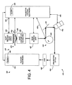
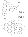
- FIG. 6 a triangular super pixel, indicated generally at 412 (FIG. 6), to produce a super pixel spot on a viewing surface or screen S.
- the super pixel 412 repetitively sweep across every addressable location on a viewing screen S in interleaved and staggered scan patterns thereby hiding the effect of burned out, misdirected, or marginally operating light-emitting sources that would otherwise result in a degraded projected image.
- the projector 410 generally includes projection optics 434 that throw super pixel 412 onto the viewing screen S in response to scanning optics 428 that facilitates both horizontal scanning and vertical scanning as will be described hereinafter in greater detail. Both the projection optics 434 and the scanning optics 428 are controlled by control electronics in the form of an image or projection controller 436.
- the projector 410 further includes a light engine or light signal generator 420 and beam optics 423.
- the beam optics 423 includes a converging lens 425 and a beam forming collimating lens 427 that are coupled together by a light coupler or waveguide 426.
- the light signal generator 420 and the beam optics 423 are controlled by the projector controller 436.
- the light signal generator 420 is substantially similar to the light signal generator 20 except that it includes a plurality of light sources 422 that are preferably arranged in a triangular array for facilitating the generation of the super pixel 412. As the light signal generator 420 is substantially similar to the light signal generator 20 it will not be described hereinafter in greater detail.
- the collimated light beams 424 produced by the plurality of light sources 422 are intercepted by the beam forming optics 423 to produce a single point super pixel 412.
- the single point super pixel 412 is focused on scanning optics 428 by the combination of a converging lens 425, the light coupler 426 and the collimating lens 427.
- the beam forming optics 423 under control of the projector controller 436, cause the plurality of beams 424 generated by the plurality of light emitting sources 422 to be focused in a collimated super pixel spot on the scanning optics 428.
- the scanning optics 428 under control of the projector controller 436, is structured to cause the super pixel spot to overwrite the entire two-dimensional plane of the viewing surface S and includes a horizontal scanner 430 and a vertical scanner 432.
- the horizontal scanner 430 in the first preferred embodiment of the present invention is an x-axis polygon or multifaceted mirror that is mounted for controlled rotational movement under the control of the projector controller 436 as will be described hereinafter in greater detail.
- the vertical scanner 432 is a y-axis polygon or multifaceted mirror 432 that is also mounted for controlled rotational movement under the control of the projector controller 436.
- the x-axis polygon mirror 430 is mounted orthogonal to the y-axis polygon mirror 432.
- the scanning optics 428 also includes a mirror 431.
- the super pixel 412 light beam sweeps out a portion of a rectangle as best seen in FIGS. 2A and 2B.
- a single beam in the super pixel 412 is activated and all the remaining beams in the super pixel 412 are deactivated a single line trace indicated in the form of a dash line 13 traces out a slanted line across the rectangle as it scans.
- each light beam within the super pixel 412 must overwrite the entire viewing screen S.
- a single light emitting diode within the plurality of light sources 422 burns out, this will only cause an overall reduction in the intensity of that color as viewed on the screen.
- the relative angular speeds of the polygon mirrors 430 and 432 must be adjusted to be a non-integer value.
- each of the scanner 430 and 432 include encoder devices that generate rotational speed signals that are coupled to the projector controller 436 via two way control lines which include a horizontal scan control line 438 and a vertical scan control line 448.
- the projector controller 34 reads the encoder signals generated by the individual ones of the polygon mirrors 430 and 432 to determine their rotational speed and then provides a feedback signals that cause the rotational speed to be maintained, increased or decreased to achieve a desired scanning pattern.
- the projector controller 434 by controlling the spin speed of the individual mirrors 430 and 432 causes the above-mentioned interleaving patterns for hiding the effect of burned out, misdirected, or marginally operating light-emitting sources that would otherwise result in a degraded projected image.
- the spin speeds of the individual mirrors 430 and 432 are not integer multiples of each other and the difference from an integer multiple impacts interleaving.
- the super pixel 412 can be controlled to move across the screen S on a first axis and then on a second axis such that the super pixel 412 is repetitively sweep across every addressable location on a viewing screen S in a randomized manner as best seen in FIGS 2A and 2B.
- FIGS 2A and 2B illustrate how the super pixel 412 moves in such a manner to cause a single dot of light produced by an individual one of said plurality of light emitting sources 422 to overwrite the entire two-dimensional plane of the viewing screen S to produce an image that hides errors due to burned out individual ones of said plurality of light emitting sources.
- the sweeping action also results in interleaved and staggered scan patterns that further hide the effect of burned out, misdirected, or marginally operating light-emitting sources that would otherwise result in a degraded projected image.
- the projector controller 436 In order to properly address individual pixel locations on the viewing screen S, the projector controller 436 must control the time on and time off values for each of the light emitting diodes in the diode array 422 relative to the rotational speed of the horizontal scanner 430 and the vertical scanner 432.
- Various errors affect the relative locations of the pixels and in particular the relative alignment of the light spots generated by the individual diode elements. To take care of these errors, alignment is performed by adjusting the timing of a given spot using a alignment system indicated generally at 440.
- the alignment system 440 includes a charge-coupled device 442 that is coupled to factory alignment electronics 444.
- the alignment system 440 includes a clock 446 that is coupled to the projector electronics 436 and its associated clock 456.
- the two clocks 446 and 456 are synchronized using a standard synchronization procedure that will not be described hereinafter in greater detail. It will suffice to indicate that the projector clock 456 is the master clock and the alignment system clock 446 is a slave clock.
- the projector control electronics 436 includes firmware that provides an indication of when a light beam generated by any individual one of the plurality of light sources 422 should arrive at any one of the addressable pixel locations on the viewing screen S.
- the charge-coupled device 442 is positioned to detect the light beam when it illuminates the screen S. In this regard, when the charge-coupled device 442 detects a spot of light provided by the projection optics 434, the charge-coupled device 442 generates a beam detection signal.
- the beam detection signal is coupled to the alignment electronics 444, which in turn, stores the detection signal in the form of a detection code that includes a header code indicative of a pixel address location that would have otherwise been displayed on the projection screen S and a time code indicative of the time the detection signal was sensed and stored by the alignment electronics 440.
- the pixel address location is in the form of x and y coordinate values that define each and every pixel location on the screen S.
- the projector controller 436 retrieves the detection code and compares it with a pre-stored alignment code that is indicative of when the beam of light generated by the projector 410 should have illuminated the addressable pixel location on the screen S.
- the projector controller firmware first checks the x-coordinate values and then the y-coordinate values for alignment. In the first instance if there is a comparison between the x-coordinate values and time values between the two codes, the projector controller firmware proceeds to check the y-coordinate values for alignment.
- the projector controller 436 determines the differences between the two codes and makes an adjustment to the x-scanner 430 by altering the timing of turning on individual light sources or LEDS.
- the projector controller 436 then retrieves a new detection code (for the same predetermined screen location) and repeats the x-coordinate alignment procedure as previously discussed. This is an iterative process until the two codes compare relative to the x-coordinate values and the time values.
- the firmware in the projector controller 436 proceeds to make a comparison between the y-coordinate values and time values between the two codes. If the projector firmware determines that there is a comparison, the projector controller generates another light beam for another predetermined addressable pixel location on the viewing screen S and then repeats the above described alignment procedure. However if there is not a proper comparison between the y-coordinate values and time values, the projector controller 436 determines the differences between the two codes and makes an adjustment to the y-scanner 432 by altering the timing of turning on individually addressable light sources or LEDS.
- the projector controller 436 generates another light beam for the same predetermined addressable pixel location on the viewing screen S.
- the projector controller 436 retrieves a new detection code (for the same predetermined screen location) and repeats the y-coordinate alignment procedure as previously discussed. This is an iterative process until the two codes compare relative to the y-coordinate values and the time values.
- the projector controller 436 generates another light beam from an additional individually addressable light source or LED. The above-described procedure is then repeated until relative alignment has been achieved between all of the individually addressable spots that make up the superpixel 412.
- each addressable pixel location it is possible to project a light beam for each of the colors red, blue, and green. It is also possible to project a light beam indicative of white light that is formed when all three-color beams are projected simultaneously onto the screen S.
- the preferred alignment method is to project a light beam indicative of white light when correcting for misalignment and to project a light beam of individual red, green and blue colors when correcting for burnt out light sources. It should also be understood by those skilled in the art that this factory alignment procedure may also be utilized with the projector10.
- FIG. 6 there is illustrated a projector 510, which is constructed in accordance with a third embodiment of the present invention.
- the projector 510 as will be explained hereinafter in greater detail, generates an irregularly shaped super pixel, indicated generally at 512 (FIG.6), to produce a spot on a viewing surface or screen S.
- the super pixel 512 repetitively swept across every addressable location on a viewing screen S in interleaved and staggered scan patterns thereby hiding the effect of burned out, misdirected, or marginally operating light-emitting sources that would otherwise result in a degraded projected image.
- the projector 510 generally includes projection optics 534 that throw or projects the super pixel 512 onto the viewing screen S in response to scanning optics 528 that facilitates both horizontal scanning and vertical scanning as will be described hereinafter in greater detail. Both the projection optics 534 and the scanning optics 528 are controlled by control electronics in the form of an image or projection controller 536.
- the projector 510 further includes a light engine or light signal generator 520 and beam optics 523.
- the beam optics 523 includes a converging lens 525 that is controlled by the projector controller 536 in order to facilitate focusing a converged beam of light indicative of the super pixel on the scanning optics 528.
- the light signal generator 520 is substantially similar to the light signal generator 20 except that it includes a plurality of light sources 522 that are arranged in an irregular shaped array for facilitating the generation of the super pixel 512. As the light signal generator 520 is substantially similar to the light signal generator 20, the light signal generator 520 will not be described hereinafter in greater detail.
- the collimated light beams 524 produced by the plurality of light sources 522 are intercepted by the beam forming optics 523 to produce a single point super pixel 512.
- the single point super pixel 512 is focused on scanning optics 528 by a single converging lens 525, which operates under the control of the projector controller 536.
- the beam forming optics 523 under control of the projector controller 536, cause the plurality of beams 524 generated by the plurality of light emitting sources 522 to be focused in a super pixel spot on the scanning optics 528.
- the scanning optics 528 under control of the projector controller 536, is structured to cause the super pixel spot to overwrite the entire two-dimensional plane of the viewing surface S and includes a horizontal scanner 530 and a vertical scanner 532.
- the horizontal scanner 530 is an x-axis polygon or multifaceted mirror that is mounted for controlled rotational movement under the control of the projector controller.
- the vertical scanner 532 is a y-axis polygon or multifaceted mirror 532 that is also mounted for controlled rotational movement under the control of the projector controller 536.
- the x-axis polygon mirror 530 is mounted orthogonal to the y-axis polygon mirror 532.
- the scanning optics 528 also includes a mirror 531.
- the super pixel 512 light beam sweeps out a portion of a rectangle as best seen in FIGS. 2A and 2B.
- a single beam in the super pixel 512 is activated and all the remaining beams in the super pixel 512 are deactivated a single line trace indicated in the form of a dash line 13 traces out a slanted line across the rectangle as it scans.
- each light beam within the super pixel 512 must overwrite the entire viewing screen S.
- a single light emitting diode within the plurality of light sources 522 burns out, this will only cause an overall reduction in the intensity of that color as viewed on the screen.
- the relative angular speeds of the polygon mirrors 530 and 532 must be adjusted to be a non-integer value.
- each of the scanner 530 and 532 include encoder devices that generate rotational speed signals that are coupled to the projector controller 536 via two way control lines which include a horizontal scan control line 538 and a vertical scan control line 540.
- the projector controller 536 reads the encoder signals generated by the individual ones of the polygon mirrors 530 and 532 to determine their rotational speed and then provides a feedback signals that cause the rotational speed to be maintained, increased or decreased to achieve a desired scanning pattern.
- the projector controller 536 by controlling the spin speed of the individual mirrors 530 and 532 causes the above-mentioned interleaving patterns for hiding the effect of burned out, misdirected, or marginally operating light-emitting sources that would otherwise result in a degraded projected image.
- the spin speeds of the individual mirrors 530 and 532 are not integer multiples of each other and the difference from an integer multiple impacts interleaving.
- the super pixel 512 can be controlled to move across the screen S on a first axis and then on a second axis such that the super pixel 512 is repetitively swept across every addressable location on a viewing screen S in a randomized manner as best seen in FIGS 2A and 2B.
- FIGS 2A and 2B illustrate how the super pixel 512 moves in such a manner to cause a single dot of light produced by an individual one of said plurality of light emitting sources 522 to overwrite the entire two-dimensional plane of the viewing screen S to produce an image that hides errors due to burned out individual ones of said plurality of light emitting sources.
- the sweeping action also results in interleaved and staggered scan patterns that further hide the effect of burned out, misdirected, or marginally operating light-emitting sources that would otherwise result in a degraded projected image.
- the projector controller 536 In order to properly address individual pixel locations on the viewing screen S, the projector controller 536 must control the time on and time off values for each of the light emitting diodes in the diode array 522 relative to the rotational speed of the horizontal scanner 530 and the vertical scanner 532. Various errors affect the relative locations of the pixels and in particular the relative alignment of the light spots generated by the individual diode elements. To take care of these errors, alignment is performed by adjusting the timing of a given spot using a charged coupled device 542 and alignment electronics 544 forming part of the projector controller 536.
- the alignment electronics 544 provides an indication of when a light beam generated by any individual one of the plurality of light sources 522 should arrive at any one of the addressable pixel locations on the viewing screen S.
- the charge-coupled device 542 is positioned to detect the light beam when it illuminates the screen S. In this regard, when the charge-coupled device 542 detects a spot of light on the screen S at a predetermined one of the addressable pixel locations on the screen S, the charge-coupled device 542 generates a beam detection signal.
- the beam detection signal is coupled to the alignment electronics 544, which in turn, stores the detection signal in the form of a detection code that includes a header code indicative of a pixel address location on the screen S that was illuminated by the light beam and a time code indicative of the time the detection signal was sensed and stored by the alignment electronics.
- the pixel address location is in the form of x and y coordinate values that define each and every pixel location on the screen S.
- the projector controller 536 retrieves the detection code and compares it with a pre-stored alignment code that is indicative of when the beam of light generated by the projector 510 should have illuminated the addressable pixel location on the screen S.
- the projector controller firmware first checks the x-coordinate values and then the y-coordinate values for alignment. In the first instance if there is a comparison between the x-coordinate values and time values between the two codes, the projector controller firmware proceeds to check the y-coordinate values for alignment.
- the projector controller 536 determines the differences between the two codes and makes an adjustment to the x-scanner 530 by either increasing or decreasing its rotational speed or by altering the timing of when the individual light sources or LEDS are turned on and off.
- the projector controller 536 then retrieves a new detection code (for the same predetermined screen location) and repeats the x-coordinate alignment procedure as previously discussed. This is an iterative process until the two codes compare relative to the x-coordinate values and the time values.
- the firmware in the projector controller 536 proceeds to make a comparison between the y-coordinate values and time values between the two codes. If the projector firmware determines that there is a comparison, the projector controller generates another light beam for another predetermined addressable pixel location on the viewing screen S and then repeats the above described alignment procedure. However if there is not a proper comparison between the y-coordinate values and time values, the projector controller 536 determines the differences between the two codes and makes an adjustment to the y-scanner 532 by altering when individual light sources are turned on and off.
- the projector controller 536 generates another light beam for the same predetermined addressable pixel location on the viewing screen S.
- the projector controller 456 then retrieves a new detection code (for the same predetermined screen location) and repeats the y-coordinate alignment procedure as previously discussed. This is an iterative process until the two codes compare relative to the y-coordinate values and the time values.
- the projector controller 536 generates another light beam for a new addressable light source. The above-described procedure is then repeated until each and every addressable light source and been aligned with respect to the remaining individually addressable light sources.
- the beam positioning electronics 536 are capable of selectively causing individual ones of the plurality of light beams generated by the light sources 520 to be activated and directed to each and every addressable pixel location or to sub-pixel (locations between pixels) on the viewing screen S.
- Computational electronics within the control electronics 536 is responsive to the beam positioning electronics and to the charge couple device 542 in order to generate alignment information.
- the alignment information in turn, is stored in storage electronics 552.
- the alignment information may then be retrieved for selected individual ones of the light emitting sources 522 which have been directed at specific one of the addressable pixel locations on the screen S to facilitate relative alignment adjustment between the selected individual one of the plurality of light beams directed to a specific one of the addressable pixel locations and other selected individual ones of the plurality of light beams directed to the same specific one of the addressable pixel locations for alignment purposes. Therefore, the foregoing embodiments are illustrative, and no single feature, procedure or element is essential to all possible combinations that may be claimed in this or a later application.
Landscapes
- Engineering & Computer Science (AREA)
- Multimedia (AREA)
- Signal Processing (AREA)
- Physics & Mathematics (AREA)
- General Physics & Mathematics (AREA)
- Computer Hardware Design (AREA)
- Theoretical Computer Science (AREA)
- Optics & Photonics (AREA)
- Control Of Indicators Other Than Cathode Ray Tubes (AREA)
- Mechanical Optical Scanning Systems (AREA)
- Control Of El Displays (AREA)
- Transforming Electric Information Into Light Information (AREA)
Abstract
Description
Claims (33)
Applications Claiming Priority (4)
| Application Number | Priority Date | Filing Date | Title |
|---|---|---|---|
| US349047 | 1994-12-02 | ||
| US10/309,425 US7193662B2 (en) | 2002-05-03 | 2002-12-03 | Projector having alignment optics and electronics |
| US309425 | 2002-12-03 | ||
| US10/349,047 US7148933B2 (en) | 2002-05-03 | 2003-01-21 | Projector having alignment optics and electronics |
Publications (2)
| Publication Number | Publication Date |
|---|---|
| EP1427200A2 true EP1427200A2 (en) | 2004-06-09 |
| EP1427200A3 EP1427200A3 (en) | 2006-11-02 |
Family
ID=32314402
Family Applications (1)
| Application Number | Title | Priority Date | Filing Date |
|---|---|---|---|
| EP03257619A Withdrawn EP1427200A3 (en) | 2002-12-03 | 2003-12-03 | Projector having optics and electronics for the alignment of light beams |
Country Status (5)
| Country | Link |
|---|---|
| US (1) | US7148933B2 (en) |
| EP (1) | EP1427200A3 (en) |
| JP (1) | JP2004206086A (en) |
| KR (1) | KR101015699B1 (en) |
| CN (1) | CN100451817C (en) |
Cited By (1)
| Publication number | Priority date | Publication date | Assignee | Title |
|---|---|---|---|---|
| US7506985B2 (en) | 2005-10-26 | 2009-03-24 | Hewlett-Packard Development Company, L.P. | Projection light source having multiple light emitting diodes |
Families Citing this family (12)
| Publication number | Priority date | Publication date | Assignee | Title |
|---|---|---|---|---|
| US7184104B2 (en) * | 2002-05-03 | 2007-02-27 | Hewlett-Packard Development Company, L.P. | Projector having scanning optics |
| US7421111B2 (en) * | 2003-11-07 | 2008-09-02 | Mitsubishi Electric Research Laboratories, Inc. | Light pen system for pixel-based displays |
| US7182463B2 (en) * | 2003-12-23 | 2007-02-27 | 3M Innovative Properties Company | Pixel-shifting projection lens assembly to provide optical interlacing for increased addressability |
| US7262816B2 (en) * | 2004-10-22 | 2007-08-28 | Fakespace Labs, Inc. | Rear projection imaging system with image warping distortion correction system and associated method |
| KR100827983B1 (en) * | 2006-12-18 | 2008-05-08 | 삼성전기주식회사 | Scanning display device with adjusting light source output time and method |
| EP2193311B1 (en) * | 2007-09-21 | 2013-05-22 | Koninklijke Philips Electronics N.V. | Method of illuminating a 3d object with a modified 2d image of the 3d object by means of a projector, and projector suitable for performing such a method |
| DE102010044875A1 (en) * | 2010-09-09 | 2012-03-15 | Limo Patentverwaltung Gmbh & Co. Kg | Illumination device for producing a linear intensity distribution in a working plane |
| JP6157065B2 (en) * | 2012-06-08 | 2017-07-05 | キヤノン株式会社 | Projection apparatus and control method thereof |
| KR102210710B1 (en) * | 2013-11-01 | 2021-02-02 | 엘지전자 주식회사 | Layer display device and operation method thereof |
| KR20240038823A (en) | 2016-12-01 | 2024-03-25 | 매직 립, 인코포레이티드 | Projector with scanning array light engine |
| CN106604007A (en) * | 2017-01-24 | 2017-04-26 | 深圳晗竣雅科技有限公司 | Diode array monochromatic projection imaging device |
| CN118646854B (en) * | 2024-08-08 | 2024-10-22 | 电子科技大学 | Gray edge control method of projector picture and curtain capable of adjusting gray edge |
Family Cites Families (14)
| Publication number | Priority date | Publication date | Assignee | Title |
|---|---|---|---|---|
| GB2108703A (en) * | 1981-10-10 | 1983-05-18 | Timothy David Joseph Stamper | Optical-mechanical scanning image display apparatus |
| US4684996A (en) * | 1986-08-25 | 1987-08-04 | Eastman Kodak Company | Video projector with optical feedback |
| US4751659A (en) * | 1987-08-26 | 1988-06-14 | Xerox Corporation | Defect compensation for discrete image bars |
| FR2660090B1 (en) * | 1990-03-23 | 1994-07-29 | Thomson Csf | DEVICE FOR VIEWING BY PROJECTION WITH A FEEDBACK LOOP FOR CORRECTING ALL OF THE DEFECTS IN THE PROJECTED IMAGE. |
| JP3409330B2 (en) * | 1991-02-08 | 2003-05-26 | ソニー株式会社 | Adjustment device and adjustment method for projection display device |
| JPH0537750A (en) * | 1991-08-02 | 1993-02-12 | Ricoh Co Ltd | Laser recorder |
| DE69427860T2 (en) * | 1993-02-03 | 2002-04-11 | Nitor, San Jose | METHOD AND DEVICE FOR PROJECTING IMAGES |
| US5534950A (en) * | 1993-10-04 | 1996-07-09 | Laser Power Corporation | High resolution image projection system and method employing lasers |
| DE4428202A1 (en) | 1994-08-09 | 1996-02-15 | Deutsche Forsch Luft Raumfahrt | Device for generating an image |
| WO1998024240A1 (en) * | 1996-11-27 | 1998-06-04 | Laser Power Corporation | Multi-beam laser scanning display system |
| JP2000263842A (en) | 1999-03-15 | 2000-09-26 | Fuji Xerox Co Ltd | Image-forming apparatus |
| JP4754682B2 (en) | 1999-11-19 | 2011-08-24 | 株式会社半導体エネルギー研究所 | Display device |
| US7102700B1 (en) * | 2000-09-02 | 2006-09-05 | Magic Lantern Llc | Laser projection system |
| CN1346115A (en) * | 2000-09-30 | 2002-04-24 | 力捷电脑股份有限公司 | A device for scanning objects |
-
2003
- 2003-01-21 US US10/349,047 patent/US7148933B2/en not_active Expired - Fee Related
- 2003-12-03 CN CNB2003101147486A patent/CN100451817C/en not_active Expired - Fee Related
- 2003-12-03 KR KR1020030087129A patent/KR101015699B1/en not_active Expired - Fee Related
- 2003-12-03 EP EP03257619A patent/EP1427200A3/en not_active Withdrawn
- 2003-12-03 JP JP2003404388A patent/JP2004206086A/en active Pending
Cited By (1)
| Publication number | Priority date | Publication date | Assignee | Title |
|---|---|---|---|---|
| US7506985B2 (en) | 2005-10-26 | 2009-03-24 | Hewlett-Packard Development Company, L.P. | Projection light source having multiple light emitting diodes |
Also Published As
| Publication number | Publication date |
|---|---|
| CN100451817C (en) | 2009-01-14 |
| CN1549045A (en) | 2004-11-24 |
| EP1427200A3 (en) | 2006-11-02 |
| JP2004206086A (en) | 2004-07-22 |
| KR20040048852A (en) | 2004-06-10 |
| US20030206249A1 (en) | 2003-11-06 |
| KR101015699B1 (en) | 2011-02-22 |
| US7148933B2 (en) | 2006-12-12 |
Similar Documents
| Publication | Publication Date | Title |
|---|---|---|
| US7193662B2 (en) | Projector having alignment optics and electronics | |
| US7148933B2 (en) | Projector having alignment optics and electronics | |
| JP3214211B2 (en) | Projection display device | |
| US8556431B2 (en) | Apparatus and method for reducing speckle in display of images | |
| US20050231651A1 (en) | Scanning display system | |
| JPH02149887A (en) | Color display device | |
| US20040130682A1 (en) | Image display apparatus and image display method | |
| CN104102003B (en) | Self-aligning imager array | |
| JP2003510624A (en) | Light beam display | |
| JP2004518168A (en) | Interlaced light beam scanning light beam display | |
| WO2014207457A1 (en) | A projection display system | |
| CN100394247C (en) | Optical scanning device, its control method, and image display device | |
| CN105900166A (en) | Image projection device, method for adjusting image projection device, and method for controlling image projection device | |
| US12556666B2 (en) | Method and system for generating a pixel stream | |
| US6860606B2 (en) | Projector having concentrated beam | |
| CN111630585B (en) | Variable emission period for scanned beam displays | |
| KR20030010682A (en) | Scrolling color projector and a method for alignment of the optical and the electrical scan thereof | |
| GB2142203A (en) | Television projection apparatus | |
| US20100141855A1 (en) | Image display apparatus | |
| HK1062099A (en) | Projector having optics and electronics for the alignment of light beams | |
| US20040160536A1 (en) | Light emitting device projection methods and systems | |
| CN111552141A (en) | Projection on multiple planes using a single projection unit | |
| JP2001004950A (en) | Video display device | |
| EP4482137A1 (en) | Method and system for generating a pixel stream | |
| JPH04181289A (en) | image display device |
Legal Events
| Date | Code | Title | Description |
|---|---|---|---|
| PUAI | Public reference made under article 153(3) epc to a published international application that has entered the european phase |
Free format text: ORIGINAL CODE: 0009012 |
|
| AK | Designated contracting states |
Kind code of ref document: A2 Designated state(s): AT BE BG CH CY CZ DE DK EE ES FI FR GB GR HU IE IT LI LU MC NL PT RO SE SI SK TR |
|
| AX | Request for extension of the european patent |
Extension state: AL LT LV MK |
|
| REG | Reference to a national code |
Ref country code: HK Ref legal event code: DE Ref document number: 1062099 Country of ref document: HK |
|
| PUAL | Search report despatched |
Free format text: ORIGINAL CODE: 0009013 |
|
| AK | Designated contracting states |
Kind code of ref document: A3 Designated state(s): AT BE BG CH CY CZ DE DK EE ES FI FR GB GR HU IE IT LI LU MC NL PT RO SE SI SK TR |
|
| AX | Request for extension of the european patent |
Extension state: AL LT LV MK |
|
| RIC1 | Information provided on ipc code assigned before grant |
Ipc: H04N 5/74 20060101ALI20060922BHEP Ipc: H04N 9/31 20060101AFI20060922BHEP |
|
| 17P | Request for examination filed |
Effective date: 20070404 |
|
| 17Q | First examination report despatched |
Effective date: 20070522 |
|
| AKX | Designation fees paid |
Designated state(s): DE FR GB |
|
| REG | Reference to a national code |
Ref country code: HK Ref legal event code: WD Ref document number: 1062099 Country of ref document: HK |
|
| STAA | Information on the status of an ep patent application or granted ep patent |
Free format text: STATUS: THE APPLICATION IS DEEMED TO BE WITHDRAWN |
|
| 18D | Application deemed to be withdrawn |
Effective date: 20150701 |