EP1427199A2 - Image processing system, projector, portable device, and image processing method - Google Patents
Image processing system, projector, portable device, and image processing method Download PDFInfo
- Publication number
- EP1427199A2 EP1427199A2 EP03256939A EP03256939A EP1427199A2 EP 1427199 A2 EP1427199 A2 EP 1427199A2 EP 03256939 A EP03256939 A EP 03256939A EP 03256939 A EP03256939 A EP 03256939A EP 1427199 A2 EP1427199 A2 EP 1427199A2
- Authority
- EP
- European Patent Office
- Prior art keywords
- projection
- image
- keystone distortion
- coordinates
- sensing
- Prior art date
- Legal status (The legal status is an assumption and is not a legal conclusion. Google has not performed a legal analysis and makes no representation as to the accuracy of the status listed.)
- Withdrawn
Links
- 238000012545 processing Methods 0.000 title claims abstract description 64
- 238000003672 processing method Methods 0.000 title claims abstract description 12
- 238000012937 correction Methods 0.000 claims abstract description 70
- 238000000605 extraction Methods 0.000 claims description 16
- 238000013507 mapping Methods 0.000 claims description 15
- 238000000034 method Methods 0.000 claims description 15
- 239000000284 extract Substances 0.000 claims description 9
- 238000001514 detection method Methods 0.000 claims description 5
- 238000003384 imaging method Methods 0.000 abstract description 4
- 238000010586 diagram Methods 0.000 description 10
- 238000006243 chemical reaction Methods 0.000 description 9
- 239000004973 liquid crystal related substance Substances 0.000 description 9
- 230000007274 generation of a signal involved in cell-cell signaling Effects 0.000 description 7
- 238000006073 displacement reaction Methods 0.000 description 4
- PCTMTFRHKVHKIS-BMFZQQSSSA-N (1s,3r,4e,6e,8e,10e,12e,14e,16e,18s,19r,20r,21s,25r,27r,30r,31r,33s,35r,37s,38r)-3-[(2r,3s,4s,5s,6r)-4-amino-3,5-dihydroxy-6-methyloxan-2-yl]oxy-19,25,27,30,31,33,35,37-octahydroxy-18,20,21-trimethyl-23-oxo-22,39-dioxabicyclo[33.3.1]nonatriaconta-4,6,8,10 Chemical compound C1C=C2C[C@@H](OS(O)(=O)=O)CC[C@]2(C)[C@@H]2[C@@H]1[C@@H]1CC[C@H]([C@H](C)CCCC(C)C)[C@@]1(C)CC2.O[C@H]1[C@@H](N)[C@H](O)[C@@H](C)O[C@H]1O[C@H]1/C=C/C=C/C=C/C=C/C=C/C=C/C=C/[C@H](C)[C@@H](O)[C@@H](C)[C@H](C)OC(=O)C[C@H](O)C[C@H](O)CC[C@@H](O)[C@H](O)C[C@H](O)C[C@](O)(C[C@H](O)[C@H]2C(O)=O)O[C@H]2C1 PCTMTFRHKVHKIS-BMFZQQSSSA-N 0.000 description 3
- 241000826860 Trapezium Species 0.000 description 2
- 238000012546 transfer Methods 0.000 description 2
- 238000009434 installation Methods 0.000 description 1
- 238000005259 measurement Methods 0.000 description 1
- 238000012986 modification Methods 0.000 description 1
- 230000004048 modification Effects 0.000 description 1
- 230000003287 optical effect Effects 0.000 description 1
- 229920001690 polydopamine Polymers 0.000 description 1
- 238000003825 pressing Methods 0.000 description 1
Images






Classifications
-
- H—ELECTRICITY
- H04—ELECTRIC COMMUNICATION TECHNIQUE
- H04N—PICTORIAL COMMUNICATION, e.g. TELEVISION
- H04N5/00—Details of television systems
- H04N5/74—Projection arrangements for image reproduction, e.g. using eidophor
-
- H—ELECTRICITY
- H04—ELECTRIC COMMUNICATION TECHNIQUE
- H04N—PICTORIAL COMMUNICATION, e.g. TELEVISION
- H04N9/00—Details of colour television systems
- H04N9/12—Picture reproducers
- H04N9/31—Projection devices for colour picture display, e.g. using electronic spatial light modulators [ESLM]
- H04N9/3191—Testing thereof
- H04N9/3194—Testing thereof including sensor feedback
-
- H—ELECTRICITY
- H04—ELECTRIC COMMUNICATION TECHNIQUE
- H04N—PICTORIAL COMMUNICATION, e.g. TELEVISION
- H04N9/00—Details of colour television systems
- H04N9/12—Picture reproducers
- H04N9/31—Projection devices for colour picture display, e.g. using electronic spatial light modulators [ESLM]
- H04N9/3179—Video signal processing therefor
- H04N9/3185—Geometric adjustment, e.g. keystone or convergence
Definitions
- the present invention relates to an image processing system, a projector, a portable device, and an image processing method that are capable of correcting keystone distortion.
- One method detects the inclination of the projector and automatically corrects keystone distortion in the vertical direction, by way of example.
- one method of correcting keystone distortion in the horizontal direction involves the user correcting the keystone distortion manually by pressing a correction switch on a remote controller while viewing the image.
- this method only discloses a method of correcting keystone distortion by detecting the distance up to the installation plane of the projector and the inclinations in the horizontal and vertical directions with respect to the horizontal plane of the projector.
- the present invention was devised in the light of the above-described technical problems, and may provide an image processing system, a projector, a portable device, and an image processing method that make it possible to correct keystone distortion, particularly keystone distortion in the horizontal direction, both automatically and appropriately.
- an image processing system comprising:
- a projector comprising:
- a portable device comprising:
- an image processing method comprising:
- the image processing system and others according to the present invention makes it possible to determine keystone distortion by sensing. They can convert the magnitude of the distortion into numerical values by converting the sensing information into histograms. They can also determine the relative displacement between the sensing direction and the projection direction by determining the angle.
- the image processing system and others can correct not only keystone distortion in the vertical direction but also keystone distortion in the horizontal direction, both automatically and appropriately, by correcting the keystone distortion, based on histogram information that expresses the distortion and direction information that expresses relative displacement between the sensing direction and the projection direction.
- the image processing system may comprise:
- the keystone distortion correction means may include:
- the image processing method may comprise:
- the keystone distortion in the horizontal direction is affected by the relative positional relationship between the image display device and the projection area.
- the keystone distortion in the vertical direction is mainly affected by the inclination of the image display device.
- the image processing system and others can therefore correct the keystone distortion as appropriate, by correcting the keystone distortion in the vertical direction, based on the inclination of the image display device, and by correcting the keystone distortion in the horizontal direction, based on histogram information and direction information that reflect the position of the projection area.
- an image processing system comprising:
- the image processing system may comprise:
- a projector comprising:
- an image processing method comprising:
- the image processing system and others according to the present invention makes it possible to determine coordinates of light of a distortion-free and predetermined shape that is projected into a projection area by sensing.
- the coordinates of the light of the predetermined shape can be taken as coordinates of a distortion-free image, and thus a distortion-free image can be projected during image projection by mapping the coordinates of an input image into those coordinates.
- the predetermined shape may be rectangular or square; the area extraction means may extract coordinates of four comers of the light of the predetermined shape; and the keystone distortion correction means may convert the coordinates of the four comers of the light of the predetermined shape in the sensed area into coordinates for projection in a spatial light modulator of the projection section, and correct keystone distortion by mapping the coordinates of an input image into an area formed by the projection coordinates of the four comers.
- the predetermined shape may be rectangular or square; and the method may include:
- a spatial light modulator such as a liquid crystal light valve
- the present invention is described below, taking as an example the application thereof to an image processing system that correct keystone distortion of a projected image by using a projector that is an image display device and a remote controller that is a portable device, with reference to the accompanying figures. Note that the embodiments described below do not in any way limit the scope of the present invention as laid out in the claims herein. In addition, the entirety of the configuration described with reference to these embodiments is not limited to being essential structural components of the present invention.
- a remote controller having a sensing means is used to sense a projection area and determine a direction, and a projector corrects keystone distortion. It also concerns a second embodiment in which a remote controller having a light projection means projects a rectangular laser beam into a projection area, and a projector corrects keystone distortion by sensing the projection area from the projection position.
- FIG. 1 An overall conceptual view of an image processing system in accordance with the first embodiment is shown in Fig. 1.
- Fig. 2 A schematic view of a projected image 70 and histograms in accordance with the first embodiment are shown in Fig. 2.
- a projector 10 that is a type of image display device projects an image from a position which is not directly in front of a projection area 30, but directed forward and to the left from a state directly facing the projection area 30, and which is also at a distance further to the right than a viewer 40 who is a user.
- the projected image 70 that the viewer 40 sees has a trapezoidal shape such that the leftmost edge is the longest and the rightmost edge is the shortest, as shown in Fig. 2.
- an imaging function is provided in a remote controller 20 that is a type of portable device manipulated by the viewer 40, enabling the remote controller 20 to sense (form an image of) the projection area 30.
- the remote controller 20 is also provided with a histogram processing function, enabling the remote controller 20 to generate a histogram 80 of the numbers of pixels in the horizontal direction and a histogram 82 of the numbers of pixels in the vertical direction, for the projected image 70 in a captured image 60.
- the remote controller 20 is further provided with a direction determination function, enabling the remote controller 20 to generate direction information based on an angle ⁇ between a normal direction ⁇ n for the orthogonal direction from a virtual viewpoint position 50 to the projection area 30 and a projected image direction ⁇ i from the virtual viewpoint position 50 to a central portion of the projected image.
- the virtual viewpoint position 50 is a position that sets the viewpoint of the viewer 40 in a virtual manner, by way of example.
- the sensing position of the remote controller 20 becomes the virtual viewpoint position 50.
- the projector 10 also has a keystone distortion correction function that corrects any keystone distortion of the projected image 70, based on the histogram information (the histogram 80 of the numbers of pixels in the horizontal direction and the histogram 82 of the numbers of pixels in the vertical direction) and the direction information.
- the image processing system of this embodiment uses these functions to correct any keystone distortion of the projected image 70 from consideration of the virtual viewpoint position 50, both automatically and appropriately.
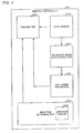
- FIG. 3 A functional block diagram of the projector 10 in accordance with this embodiment is shown in Fig. 3.
- the projector 10 comprises an input signal processing section 110, a color conversion section 120, an output signal processing section 130, an image projection section 190, a keystone distortion correction section 140, and a receiver section 160.
- the input signal processing section 110 converts an R1 signal, a G1 signal, and a B1 signal (which form RGB signals in analog form that is a type of input image information that is input from a personal computer (PC) or the like) into an R2 signal, a G2 signal, and a B2 signal in digital form.
- R1 signal a G1 signal
- B1 signal which form RGB signals in analog form that is a type of input image information that is input from a personal computer (PC) or the like
- the input signal processing section 110 comprises an A/D converter section 112 that performs this analog-to-digital conversion and a resizing section 114 that functions as part of a keystone distortion correction means to adjust the position and dimensions of the projected image 70 by adjusting the input image signal.
- a calibration signal generation section 150 generates an R2 signal, a G2 signal, and a B2 signal in digital format that are used for displaying a calibration image.
- the color conversion section 120 outputs an R3 signal, a G3 signal, and a B3 signal having a color temperature that has been corrected on the basis of a standard setting for the liquid-crystal projector, based on the R2 signal, G2 signal, and B2 signal from the input signal processing section 110 or the calibration signal generation section 150.
- the output signal processing section 130 comprises a D/A converter section 132.
- the D/A converter section 132 converts the R3 signal, G3 signal, and B3 signal from the color conversion section 120 into an R4 signal, a G4 signal, and a B4 signal in analog format.
- A/D converter section 112 and the D/A converter section 132 are not necessary if the projector 10 uses only RGB signals in digital format.
- the image projection section 190 that functions as projection means comprises a spatial light modulator 192, a drive section 194 for driving the spatial light modulator 192, a light source 196, and a lens 198.
- the drive section 194 drives the spatial light modulator 192, based on the R4 signal, G4 signal, and B4 signal from the output signal processing section 130.
- the image projection section 190 projects light from the light source 196 through the spatial light modulator 192 and the lens 198.
- the receiver section 160 receives histogram information and direction information that is transmitted from the remote controller 20.
- the keystone distortion correction section 140 comprises a vertical keystone distortion correction section 141, which has an inclination sensor 142 and which corrects keystone distortion in the vertical direction, and a horizontal keystone distortion correction section 143, which has a 3D-LUT 144 and which corrects keystone distortion in the horizontal direction.
- the inclination sensor 142 detects any inclination in the vertical direction of the projector 10, and the vertical keystone distortion correction section 141 transmits a vertical keystone distortion correction value that corresponds to that inclination (such as an integer value from -n to n, similar to that for manual adjustment) to the resizing section 114.
- the horizontal keystone distortion correction section 143 takes the histogram information and direction information that has been received by the receiver section 160, selects a horizontal direction keystone distortion correction stored in the 3D-LUT 144 corresponding thereto (such as an integer value from -n to n, similar to that for manual adjustment), and transmits the thus-selected horizontal direction keystone distortion correction value to the resizing section 114.
- FIG. 4 A functional block diagram of the remote controller 20 in accordance with this embodiment is shown in Fig. 4.
- the remote controller 20 comprises an area sensor section 210 that functions as sensing means to obtain the captured image 60 by using a sensor such as a CCD sensor to image the projection area 30, a projected image area extraction section 220 that extracts the projected image 70 from the captured image 60, and a histogram processing section 230 that functions as histogram generation means for generating the histogram 80 of the numbers of pixels in the horizontal direction and the histogram 82 of the numbers of pixels in the vertical direction of the projected image 70.
- a sensor such as a CCD sensor to image the projection area 30
- a projected image area extraction section 220 that extracts the projected image 70 from the captured image 60
- a histogram processing section 230 that functions as histogram generation means for generating the histogram 80 of the numbers of pixels in the horizontal direction and the histogram 82 of the numbers of pixels in the vertical direction of the projected image 70.
- the projected image area extraction section 220 extracts a brightness detection area of pixels of a maximum brightness, such as those of greater than 65% or 80% brightness, from the captured image 60 as the projected image 70.
- the histogram processing section 230 generates the totals of the numbers of pixels for each scan line, when the projected image 70 is scanned in the horizontal direction, as the histogram 80 of the numbers of pixels in the horizontal direction and the totals of the numbers of pixels for each scan line, when the projected image 70 is scanned in the vertical direction as the histogram 82 of the numbers of pixels in the vertical direction, as shown in Fig. 2.
- the histogram processing section 230 also calculates the ratio of an upper-base length a to a lower-base length b from the histogram 80 of the numbers of pixels in the horizontal direction and the sign of a value obtained by subtracting a lower-base length d from an upper-base length c of the histogram 82 of the numbers of pixels in the vertical direction, and transmits them as histogram information to a transmitter section 250.
- the ratio of the upper-base length a to the lower-base length b of the histogram 80 of the numbers of pixels in the horizontal direction represents the magnitude of the distortion.
- the magnitude of the distortion increases as this ratio increases, by way of example.
- the sign of the value obtained by subtracting the lower-base length d from the upper-base length c of the histogram 82 of the numbers of pixels in the vertical direction represents the direction of the distortion in either the right or left direction.
- the histogram information can therefore be termed information that represents keystone distortion as numerical values.
- the remote controller 20 comprises a direction determination section 240 having a direction sensor 242, and the transmitter section 250 that transmits histogram information comprising the histogram 80 of the numbers of pixels in the horizontal direction and the histogram 82 of the numbers of pixels in the vertical direction from the histogram processing section 230 and direction information from the direction determination section 240, to the projector 10.
- the direction determination section 240 uses the direction sensor 242 to measure the normal direction ⁇ n of the optical axis in the direction perpendicular to the projection area 30 from the virtual viewpoint position 50 and the projected image direction ⁇ i of a central portion of the projected image 70 from the virtual viewpoint position 50, as shown in Fig. 1, and generates direction information that represents an angle ⁇ obtained by subtracting the projected image direction ⁇ i from the normal direction ⁇ n to obtain an angle ⁇ .
- the direction information represents the positional relationship between the virtual viewpoint position 50 and the projector 10. If the angle ⁇ is zero, by way of example, the projector 10 is directly in front of the viewer 40, a positive value of angle ⁇ indicates that the projector 10 is to the right of the viewer 40, and a negative value of angle ⁇ indicates that the projector 10 is to the left of the viewer 40.
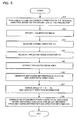
- FIG. 5 A flowchart of the flow of keystone distortion correction in accordance with this embodiment is shown in Fig. 5.
- the vertical keystone distortion correction section 141 transmits a vertical keystone distortion correction value corresponding to the inclination of the projector 10 in the vertical direction, as detected by the inclination sensor 142, to the resizing section 114.
- the resizing section 114 resizes the input image signal to perform a keystone distortion correction in the vertical direction (step S1).
- the calibration signal generation section 150 generates a calibration signal that causes the display of a completely white maximum grayscale image, and the image projection section 190 projects that (step S2).
- the viewer 40 points the remote controller 20 in the direction perpendicular to the projection area 30 and presses a normal direction measurement button on the remote controller 20.
- the direction determination section 240 measures the normal direction ⁇ n (step S3).
- the viewer 40 then points the remote controller 20 toward the vicinity of the center of the projected image 70, which maintaining the horizontal orientation thereof, and presses a keystone distortion correction button.
- the direction determination section 240 measures the projected image direction ⁇ i (step S4).
- the area sensor section 210 senses the projection area 30 and extracts the area of the projected image 70 from the captured image 60 (step S5).
- the histogram processing section 230 generates the histogram 80 of the numbers of pixels in the horizontal direction and the histogram 82 of the numbers of pixels in the vertical direction, based on the projected image 70, derives the above-described a, b, c, and d values, and generates the histogram information (step S6).
- the transmitter section 250 of the remote controller 20 transmits the histogram information and direction information to the projector 10.
- the receiver section 160 of the projector 10 receives the histogram information and direction information from the remote controller 20.
- the horizontal keystone distortion correction section 143 sends a horizontal direction keystone distortion correction value, that is based on a correction value from the 3D-LUT 144 corresponding to the histogram information and direction information, to the resizing section 114.
- the resizing section 114 corrects the keystone distortion in the horizontal direction by correcting the input image signal in such a manner that the keystone distortion in the horizontal direction is corrected thereby, based on that correction value (step S8).
- FIG. 6 A block diagram of the hardware of the projector 10 in accordance with this embodiment is shown in Fig. 6.
- the configuration could be implemented by an A/D converter 930 or the like as the A/D converter section 112; an image processing circuit 970, RAM 950, and a CPU 910 or the like as the color conversion section 120 and the keystone distortion correction section 140; a D/A converter 940 or the like as the D/A converter section 132; and a liquid-crystal panel 920 and a ROM 960 in which is stored liquid-crystal light valve drivers for driving the liquid-crystal panel 920 as the spatial light modulator 192.
- the transfer paths between the projector 10 and the remote controller 20 could be either cables or wireless. Infrared ports or the like could be used for wireless information exchange or input-output ports or the like could be used for wired information exchange, between the receiver section 160 of the projector 10 and the transmitter section 250 of the remote controller 20.
- the rest of the hardware of the remote controller 20 could be implemented by using a CCD sensor or the like as the area sensor section 210 and image processing circuitry as the projected image area extraction section 220 and the histogram processing section 230.
- these components could be implemented in a hardware manner by circuitry or in a software manner by drivers.
- the keystone distortion correction section 140 could also be implemented by reading from an information storage medium 900 a program that causes a computer to function as the keystone distortion correction section 140, to cause the computer to function as the keystone distortion correction section 140.
- the information storage medium 900 could be a CD-ROM, DVD-ROM, ROM, RAM, or HDD, by way of example, and the method of reading the program therefrom could be a direct method or an indirect method.
- this embodiment makes it possible for the image processing system to determine the keystone distortion by sensing from the virtual viewpoint position 50 which is the sensing position.
- the image processing system can convert the magnitude of the distortion into numerical values by converting the sensing information into the histogram 80 of the numbers of pixels in the horizontal direction and the histogram 82 of the numbers of pixels in the vertical direction.
- the image processing system can determine any relative displacement between the sensing direction and the projection direction by determining the angle ⁇ .
- the image processing system can also correct not only keystone distortion in the vertical direction, but also keystone distortion in the horizontal direction, both automatically and appropriately, by correcting the keystone distortion based on histogram information that represents the distortion circumstances and direction information that represents the relative displacement between the sensing direction and the projection direction.
- the keystone distortion in the horizontal direction varies with the relative positional relationship between the projector 10 and the projection area 30, whereas the keystone distortion in the vertical direction is mainly affected by the inclination of the projector 10.
- the image processing system can therefore use the inclination sensor 142 provided in the projector 10 to correct keystone distortion in the vertical direction and also use the histogram information that represents the relative positional relationship between the projector 10 and the projection area 30 to correct keystone distortion in the horizontal direction, it can correct keystone distortion in both the vertical direction and the horizontal direction as appropriate.
- the virtual viewpoint position 50 in this second embodiment is the position from which the laser beam is projected.
- FIG. 7 A schematic view of the projected image 70 and a laser beam projected image 90 in accordance with the second embodiment is shown in Fig. 7.
- a laser beam is projected from the remote controller operated by the viewer 40 within the projected image 70, in a rectangular form as seen by the viewer 40.
- the captured image 60 comprises the projected image 70 that is a trapezium ABCD and the laser beam projected image 90 that is a rectangle EFGH within the trapezium ABCD.
- the laser beam projected image 90 is preferably formed within the projected image 70.
- the projected image 70 is reshaped into a rectangle to correct keystone distortion, by associating the coordinates of the four comers of the rectangle EFGH with four conversion coordinates within the spatial light modulator 192 then mapping the coordinates of the input image into those four conversion coordinates.
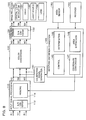
- FIG. 8 A functional block diagram of the projector 10 in accordance with this embodiment is shown in Fig. 8.
- FIG. 9 A functional block diagram of a remote controller 21 in accordance with this embodiment is shown in Fig. 9.
- the remote controller 21 of this embodiment comprises a laser beam projection section 280 that functions as a light projection means, an operating section 270, and a transmitter section 260 that transmits signals such as an operation-start signal to the projector 10.
- the projector 10 of this embodiment has a similar configuration to that of the projector 10 of Fig. 3, described as the first embodiment, except that it differs from the projector 10 of Fig. 3 in the functions of the keystone distortion correction section 140 and in the provision of an area sensor section 180 that functions as sensing means.
- the keystone distortion correction section 140 of this embodiment comprises a control section 145, a determination section 146, a coordinate conversion section 147, and an area extraction section 148 that extracts the coordinates of the four comers of the projected image 70 in the captured image 60 and the coordinates of the four comers of the laser beam projected image 90 in the captured image 60, based on sensing information.
- the area sensor section 180 is provided with the projector 10 of Fig. 1, for sensing the projection area 30 from the projection position 52.
- the brightness and color of the projected image 70 differ from the brightness and color of the laser beam projected image 90. It is therefore possible for the area extraction section 148 to distinguish between the laser beam projected image 90 and the projected image 70 within the captured image 60, by demarcating in accordance with brightness or color.
- FIG. 10 A flowchart of the flow of processing by the remote controller 20 in accordance with this embodiment is shown in Fig. 10.
- the description relates to the flow of processing by the remote controller 21.
- the viewer faces the projection area 30 and presses a distortion correction button of the remote controller 21.
- the viewer 40 presses a projection button of the remote controller 21 when a patch (calibration image) is projected by the projector 10 (step S12). This makes the operating section 270 output a control signal to the laser beam projection section 280 to make it output a laser beam.
- the laser beam projection section 280 projects a rectangular laser beam based on the control signal (step S13).
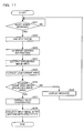
- FIG. 11 A flowchart of the flow of processing by the projector 10 in accordance with this embodiment is shown in Fig. 11.
- the determination section 146 determines whether or not the receiver section 160 has received a keystone distortion correction start signal from the remote controller 21 (step S21).
- the image projection section 190 projects a completely-white patch, based on a calibration signal by the calibration signal generation section 150 (step S22).
- the viewer 40 adjusts the position and direction of the remote controller 21 in such a manner that the laser beam is displayed as a rectangle within the projected image 70 of the patch.
- the area sensor section 180 senses the projection area 30 in which the laser beam projected image 90 and the projected image 70 are displayed, and generates sensing information (step S23).
- the area extraction section 148 extracts the projected image area (the coordinates of the sensed area defined by the four comers ABCD of the projected image 70) that has brightnesses within the range of the projected light, based on the sensing information (step S24).
- the area extraction section 148 extracts the laser frame area (the coordinates of the sensed area defined by the four comers EFGH of the laser beam projected image 90) that has brightnesses within the range of the laser beam, based on the sensing information (step S25).
- the determination section 146 determines whether or not the laser frame area is within the projected image area, based on the coordinates extracted by the area extraction section 148 (step S26).
- the coordinate conversion section 147 converts the coordinates EFGH of the laser frame area into coordinates E'F'G'H' in the processing system of the spatial light modulator 192 of the image projection section 190 (step S27).
- the resizing section 114 maps the input image signal into an area formed by the coordinates E'F'G'H'.
- the image projection section 190 projects an image based on the thus-mapped image information (step S29).
- control section 145 outputs a control signal to the calibration signal generation section 150, so as to cause the projection of a message image prompting the viewer 40 to project the laser frame area into the projected image area.
- the calibration signal generation section 150 generates the signal for that message image and the image projection section 190 displays the message based on the signal for that message image (step S28).
- this embodiment makes it possible to determine the coordinates of a rectangle of light created by light of a rectangular shape projected into the projection area 30 in a state in which there is no distortion when seen from the virtual viewpoint position 50, by sensing from the projection position 52.
- the coordinates of the rectangle of light enable the capture of the coordinates of a distortion-free image, and a distortion-free image can be projected during the projection of images by mapping the coordinates of the input image onto those coordinates.
- an input image signal is mapped into a laser frame area in the second embodiment, but it is equally possible to use laser beam information only in the obtaining of distortion information.
- the viewer 40 is assumed to be placed facing the projection area 30 in the second embodiment, but the configuration could be such that the direction determination section 240 of the remote controller 20 of the first embodiment is provided in the remote controller 21 of the second embodiment, and the histogram processing section of the remote controller 20 of the first embodiment and the 3D-LUT of the projector 10 of the first embodiment are provided in the projector 10 of the second embodiment.
- the necessity of positioning the viewer 40 facing the projection area 30 can be removed by having the projector 10 determine the direction and laser beam distortion information, to perform keystone distortion correction.
- the laser beam was described as seeming to be rectangular, by way of example, but it could equally well be another shape such as square or circular.
- any light that can be distinguished from the projected image 70 can be used therefore, such as infrared light.
- the inclination sensor 142 is used in the correction of the keystone distortion in the vertical direction, but keystone distortion in both the vertical and horizontal directions could be corrected on the basis of the histogram information and direction information alone, without using the inclination sensor 142.
- the projector 10 could correct keystone distortion by obtaining zoom-related information (such as numerical values that express the state at the furthest distance as 0 and the state at the widest angle as 1).
- the remote controller is used to measure the projected image direction ⁇ i in the vicinity of the center of the projected image 70 and sense the projection area 30, in the processing of steps S4 and S5, but the following processing could be used to ensure that the remote controller is directed reliably toward the center of the projected image 70.
- the configuration could be such that the projector 10 displays a predetermined mark (such as an "X") at the center of the projected image 70, the user uses a laser pointing function of the remote controller 20 to press the keystone distortion correction button while superimposing a laser beam on that predetermined mark, and the remote controller 20 measures the projected image direction ⁇ i and senses the projection area 30.
- a predetermined mark such as an "X”
- the remote controller 20 measures the projected image direction ⁇ i and senses the projection area 30.
- the calibration patch was described as being a completely-white image, but it is not limited to being completely white and thus various other calibration images could be used therefore.
- the configuration of the image processing system and the distribution of functions between the projector 10 and the remote controllers 20 and 21 are also not limited to those of the above-described embodiments.
- the functions of the projected image area extraction section 220 and the histogram processing section 230 of the first embodiment could be provided in the projector 10 of the first embodiment, by way of example.
- the function of the horizontal keystone distortion correction section 143 of the projector 10 of the first embodiment could be provided in the remote controller 20.
- the function of the keystone distortion correction section 140 of the second embodiment could be provided in the remote controller 21.
- the virtual viewpoint position 50 and the projection position 52 are not limited to those shown in Fig. 1.
- the remote controllers 20 and 21 were used as portable devices, but other portable devices such as handy terminals, PDAs, or mobile phones could equally well be used therefore.
- DMD digital micromirror device
- the functions of the above-described projector 10 could be implemented by the projector alone, by way of example, or they could be implemented by distributing them between a plurality of processing devices (such as between the projector and a PC).
Landscapes
- Engineering & Computer Science (AREA)
- Multimedia (AREA)
- Signal Processing (AREA)
- Physics & Mathematics (AREA)
- Geometry (AREA)
- Transforming Electric Information Into Light Information (AREA)
- Projection Apparatus (AREA)
- Controls And Circuits For Display Device (AREA)
Abstract
Description
- vertical keystone distortion correction means having inclination detection means for detecting the inclination of the image display device, for correcting keystone distortion in the vertical direction; and
- horizontal keystone distortion correction means for correcting keystone distortion in the horizontal direction, based on the histogram information and the direction information.
the area extraction means may extract coordinates of four comers of the light of the predetermined shape; and
the keystone distortion correction means may convert the coordinates of the four comers of the light of the predetermined shape in the sensed area into coordinates for projection in a spatial light modulator of the projection section, and correct keystone distortion by mapping the coordinates of an input image into an area formed by the projection coordinates of the four comers.
ally and appropriately.
Claims (14)
- An image processing system comprising:sensing means for sensing a projection area on which an image is projected and outputting sensing information;histogram generation means for generating histogram information that expresses histograms of the numbers of pixels of the sensed image in each of the vertical and horizontal directions, based on the sensing information;direction determination means for generating direction information, based on an angle between a normal direction orthogonal to the projection area from a sensing position and a projected image direction toward a central portion of the projected image from the sensing position; andkeystone distortion correction means for correcting keystone distortion of the projected image, based on the histogram information and the direction information.
- The image processing system as defined in claim 1, comprising:wherein the keystone distortion correction means includes:a portable device having the sensing means, the histogram generation means, and the direction determination means; andan image display device having the keystone distortion correction means and projection means for projecting an image,vertical keystone distortion correction means having inclination detection means for detecting the inclination of the image display device, for correcting keystone distortion in the vertical direction; andhorizontal keystone distortion correction means for correcting keystone distortion in the horizontal direction, based on the histogram information and the direction information.
- An image processing system comprising:light projection means for projecting light of a distortion-free and predetermined shape into a projection area;sensing means for outputting sensing information obtained by sensing the projection area into which the light of the predetermined shape is projected, from a projection position of a projection section for projecting an image;area extraction means for extracting coordinates of the light of the predetermined shape in a sensed area, based on the sensing information; andkeystone distortion correction means for converting the coordinates of the light of the predetermined shape in the sensed area into coordinates for projection in a spatial light modulator of the projection section, and correcting keystone distortion by mapping coordinates of an input image into the projection coordinates.
- The image processing system as defined in claim 3, wherein:the predetermined shape is rectangular or square;the area extraction means extracts coordinates of four comers of the light of the predetermined shape; andthe keystone distortion correction means converts the coordinates of the four comers of the light of the predetermined shape in the sensed area into coordinates for projection in a spatial light modulator of the projection section, and corrects keystone distortion by mapping the coordinates of an input image into an area formed by the projection coordinates of the four comers.
- The image processing system as defined in claim 3 or 4, comprising:a portable device having the light projection means; andan image display device having the sensing means, the keystone distortion correction means, and the projection section.
- A projector comprising:projection means for projecting an image;receiving means for receiving histogram information that expresses histograms of the numbers of pixels of the sensed image in each of the vertical and horizontal directions, based on sensing information obtained by sensing a projection area on which the projected image is projected, and direction information based on an angle between a normal direction orthogonal to a projection area from a sensing position and a projected image direction toward a central portion of the projected image from the sensing position; andkeystone distortion correction means for correcting keystone distortion of the projected image, based on the histogram information and the direction information.
- The projector as defined in claim 6,
wherein the keystone distortion correction means includes:vertical keystone distortion correction means having inclination detection means for detecting the inclination of the projection means, for correcting keystone distortion in the vertical direction; andhorizontal keystone distortion correction means for correcting keystone distortion in the horizontal direction, based on the histogram information and the direction information. - A projector comprising:sensing means for outputting sensing information obtained by sensing a projection area into which light of a distortion-free and predetermined shape is projected, from a projection position of a projection section for projecting an image;area extraction means for extracting coordinates of the light of the predetermined shape in a sensed area, based on the sensing information;keystone distortion correction means for converting the coordinates of the light of the predetermined shape in the sensed area into coordinates for projection in a spatial light modulator of the projection section, and correcting keystone distortion by mapping coordinates of an input image into the projection coordinates; andthe projection section.
- The projector as defined in claim 8, wherein:the predetermined shape is rectangular or square;the area extraction means extracts coordinates of four comers of the light of the predetermined shape; andthe keystone distortion correction means converts the coordinates of the four comers of the light of the predetermined shape in the sensed area into coordinates for projection in a spatial light modulator of the projection section, and corrects keystone distortion by mapping the coordinates of an input image into an area formed by the projection coordinates of the four comers.
- A portable device comprising:sensing means for sensing a projection area on which an image is projected;histogram generation means for generating histogram information that expresses histograms of the numbers of pixels of the sensed image in each of the vertical and horizontal directions, based on sensing information obtained by the sensing means;direction determination means for determining direction information based on an angle between a normal direction orthogonal to the projection area from a sensing position and a projected image direction toward a central portion of the projected image from the sensing position; andtransmitter means for correcting keystone distortion of the projected image, based on the histogram information and the direction information, and transmitting the histogram information and the direction information to an image display device that projects the projected image.
- An image processing method comprising:sensing a projection area on which an image is projected and outputting sensing information;generating histogram information that expresses histograms of the numbers of pixels of the sensed image in each of the vertical and horizontal directions, based on the sensing information;detecting a normal direction orthogonal to the projection area from a sensing position;detecting a projected image direction toward a central portion of the projected image from the sensing position;generating direction information, based on an angle between the normal direction and the projected image direction; andcorrecting keystone distortion of the projected image, based on the histogram information and the direction information.
- The image processing method as defined in claim 11, comprising:detecting inclination of an image display device;correcting keystone distortion in the vertical direction, based on the detected inclination; andcorrecting keystone distortion in the horizontal direction, based on the histogram information and the direction information.
- An image processing method comprising:projecting light of a distortion-free and predetermined shape into a projection area;outputting sensing information obtained by sensing the projection area into which the light of the predetermined shape is projected, from a projection position of a projection section for projecting an image;extracting coordinates of the light of the predetermined shape in a sensed area, based on the sensing information; andconverting the coordinates of the light of the predetermined shape in the sensed area into coordinates for projection in a spatial light modulator of the projection section, and correcting keystone distortion by mapping coordinates of an input image into the in the sensed area projection coordinates.
- The image processing method as defined in claim 13,
wherein the predetermined shape is rectangular or square; and the method including:extracting coordinates of four comers of the light of the predetermined shape when coordinates of the light of the predetermined shape in the sensed area are extracted; andconverting the coordinates of the four comers of the light of the predetermined shape in the sensed area into coordinates for projection in the spatial light modulator of the projection section, and correcting keystone distortion by mapping coordinates of an input image into an area formed by the projection coordinates of the four comers, when the keystone distortion is corrected.
Applications Claiming Priority (2)
| Application Number | Priority Date | Filing Date | Title |
|---|---|---|---|
| JP2002352247 | 2002-12-04 | ||
| JP2002352247A JP3731663B2 (en) | 2002-12-04 | 2002-12-04 | Image processing system, projector, and image processing method |
Publications (2)
| Publication Number | Publication Date |
|---|---|
| EP1427199A2 true EP1427199A2 (en) | 2004-06-09 |
| EP1427199A3 EP1427199A3 (en) | 2005-07-06 |
Family
ID=32310717
Family Applications (1)
| Application Number | Title | Priority Date | Filing Date |
|---|---|---|---|
| EP03256939A Withdrawn EP1427199A3 (en) | 2002-12-04 | 2003-11-03 | Image processing system, projector, portable device, and image processing method |
Country Status (6)
| Country | Link |
|---|---|
| US (1) | US7036940B2 (en) |
| EP (1) | EP1427199A3 (en) |
| JP (1) | JP3731663B2 (en) |
| KR (2) | KR100622164B1 (en) |
| CN (1) | CN100505851C (en) |
| TW (1) | TWI275824B (en) |
Cited By (5)
| Publication number | Priority date | Publication date | Assignee | Title |
|---|---|---|---|---|
| EP1608160A1 (en) * | 2004-06-16 | 2005-12-21 | Seiko Epson Corporation | Projector and image correction method |
| EP1710620A1 (en) * | 2005-04-06 | 2006-10-11 | Seiko Epson Corporation | Projector trapezoidal correction |
| EP1677530A3 (en) * | 2004-12-30 | 2007-05-30 | Mondo Systems, Inc. | Device and method for arranging a new display |
| US10578955B2 (en) | 2016-03-31 | 2020-03-03 | Sony Corporation | Image projection system and correction method that corrects a shape of a projection plane |
| DE112006003735B4 (en) * | 2006-02-10 | 2020-03-26 | Sharp K.K. | Image projection method and projector |
Families Citing this family (54)
| Publication number | Priority date | Publication date | Assignee | Title |
|---|---|---|---|---|
| JP3541845B1 (en) * | 2003-02-17 | 2004-07-14 | セイコーエプソン株式会社 | Image correction method for projector and projector |
| JP2005149420A (en) * | 2003-11-19 | 2005-06-09 | Sanyo Electric Co Ltd | Image processing apparatus, image processing method and image processing program |
| JP3888465B2 (en) * | 2004-05-26 | 2007-03-07 | セイコーエプソン株式会社 | Image processing system, projector, and image processing method |
| JP4380557B2 (en) * | 2005-02-15 | 2009-12-09 | カシオ計算機株式会社 | Projector, chart image display method and program |
| US20070030452A1 (en) * | 2005-08-08 | 2007-02-08 | N-Lighten Technologies | Image adaptation system and method |
| US20070064206A1 (en) * | 2005-09-21 | 2007-03-22 | N-Lighten Technologies | Rear projection display and assembly method for same |
| US7901094B2 (en) * | 2007-01-24 | 2011-03-08 | Seiko Epson Corporation | View projection: one-touch setup of light displays on arbitrary surfaces |
| US8626789B2 (en) * | 2007-06-01 | 2014-01-07 | Microsoft Corporation | Geocoding using information retrieval |
| JP4702377B2 (en) * | 2008-02-18 | 2011-06-15 | セイコーエプソン株式会社 | Control system and controlled device |
| KR101428064B1 (en) * | 2008-02-22 | 2014-08-07 | 엘지전자 주식회사 | Apparatus and method for correcting screen distortion |
| US8393740B2 (en) * | 2009-03-12 | 2013-03-12 | Canon Kabushiki Kaisha | Image projection system with keystone correction |
| US8106949B2 (en) * | 2009-03-26 | 2012-01-31 | Seiko Epson Corporation | Small memory footprint light transport matrix capture |
| US7901095B2 (en) * | 2009-03-27 | 2011-03-08 | Seiko Epson Corporation | Resolution scalable view projection |
| JP5430254B2 (en) * | 2009-07-01 | 2014-02-26 | キヤノン株式会社 | Image display apparatus and control method thereof |
| JP5428600B2 (en) * | 2009-07-09 | 2014-02-26 | セイコーエプソン株式会社 | Projector, image projection system, and image projection method |
| JP5327468B2 (en) * | 2009-08-04 | 2013-10-30 | セイコーエプソン株式会社 | Projector, program, information storage medium, and trapezoidal distortion correction method |
| JP4856263B2 (en) * | 2009-08-07 | 2012-01-18 | シャープ株式会社 | Captured image processing system, image output method, program, and recording medium |
| TWI439788B (en) * | 2010-01-04 | 2014-06-01 | Ind Tech Res Inst | System and method for projection correction |
| TWI423069B (en) * | 2010-03-18 | 2014-01-11 | 宏碁股份有限公司 | Method for setting connection, connection system using the same, and remote control device thereof |
| TWI463241B (en) * | 2010-12-29 | 2014-12-01 | Hon Hai Prec Ind Co Ltd | Portrable electronic device |
| TWI516119B (en) * | 2011-01-25 | 2016-01-01 | 華晶科技股份有限公司 | Electronic device, image capturing device and method thereof |
| CN102162979B (en) * | 2011-04-08 | 2013-12-04 | 广东威创视讯科技股份有限公司 | Method and device for automatically adjusting image projected by projector |
| CN103091947A (en) * | 2011-11-02 | 2013-05-08 | 中强光电股份有限公司 | Projection device and operation method thereof |
| US9600091B2 (en) | 2012-01-05 | 2017-03-21 | Seiko Epson Corporation | Display device and display control method |
| JP5924020B2 (en) * | 2012-02-16 | 2016-05-25 | セイコーエプソン株式会社 | Projector and projector control method |
| JP5970879B2 (en) * | 2012-03-14 | 2016-08-17 | 株式会社リコー | Projection system, projection method, program, and recording medium |
| JP6037210B2 (en) * | 2012-09-11 | 2016-12-07 | 株式会社リコー | Image projection system, operation method of image projection system, image projection apparatus, and remote operation apparatus for image projection system |
| JP6464748B2 (en) * | 2013-01-22 | 2019-02-06 | ソニー株式会社 | Projection-type image display device, image processing device, image processing method, and computer program |
| JP2018124441A (en) * | 2017-02-01 | 2018-08-09 | キヤノン株式会社 | System, information processing apparatus, information processing method, and program |
| WO2018189867A1 (en) * | 2017-04-13 | 2018-10-18 | Necディスプレイソリューションズ株式会社 | Projector, remote controller, projector system and distortion correction method |
| CN108769636B (en) * | 2018-03-30 | 2022-07-01 | 京东方科技集团股份有限公司 | Projection method and device and electronic equipment |
| CN110784692B (en) | 2018-07-31 | 2022-07-05 | 中强光电股份有限公司 | Projection device, projection system and image correction method |
| CN110784691B (en) | 2018-07-31 | 2022-02-18 | 中强光电股份有限公司 | Projection device, projection system and image correction method |
| KR102605035B1 (en) * | 2019-02-22 | 2023-11-24 | 삼성전자주식회사 | Electronic device comprising projector |
| KR20220005436A (en) * | 2019-04-26 | 2022-01-13 | 소니그룹주식회사 | image display device |
| CN112863409B (en) * | 2019-11-28 | 2024-07-19 | 中强光电股份有限公司 | Projector control method and system |
| KR102803131B1 (en) | 2020-04-02 | 2025-05-07 | 삼성전자주식회사 | Image projecting apparatus and controlling method thereof |
| CN112004072B (en) * | 2020-07-31 | 2022-05-03 | 海尔优家智能科技(北京)有限公司 | Projection image detection method and device |
| JP2022126436A (en) * | 2021-02-18 | 2022-08-30 | 富士フイルム株式会社 | Projection type display device |
| WO2022185308A1 (en) * | 2021-03-04 | 2022-09-09 | Rail Vision Ltd | System and method for verifying a selection of an optical sensor |
| EP4283986A4 (en) | 2021-06-01 | 2024-08-07 | Samsung Electronics Co., Ltd. | ELECTRONIC DEVICE AND ITS CONTROL METHOD |
| CN117795287A (en) * | 2021-08-13 | 2024-03-29 | 国立大学法人东京大学 | Information processing device, computer program and pattern code |
| US12244974B1 (en) * | 2022-01-11 | 2025-03-04 | Noah Buffett-Kennedy | Vehicular projection system |
| US12322139B2 (en) * | 2022-02-28 | 2025-06-03 | Basis Software, Inc. | System and method for camera calibration |
| US11947243B2 (en) * | 2022-03-24 | 2024-04-02 | Changzhou Aac Raytech Optronics Co., Ltd. | Auto-focus apparatus for camera |
| US11982932B2 (en) * | 2022-03-25 | 2024-05-14 | Light Show Technology Co., LTD. | Projection display device |
| US12450777B2 (en) * | 2022-06-01 | 2025-10-21 | Proprio, Inc. | Methods and systems for calibrating and/or verifying a calibration of an imaging system such as a surgical imaging system |
| JP2024032232A (en) * | 2022-08-29 | 2024-03-12 | セイコーエプソン株式会社 | Display method, portable information processing device, and program |
| KR20240125760A (en) * | 2023-02-09 | 2024-08-20 | 삼성디스플레이 주식회사 | Image quality inspection method, image quality inspection system performing the same and display device to which the same is applied |
| US12293548B2 (en) * | 2023-04-21 | 2025-05-06 | Toyota Research Institute, Inc. | Systems and methods for estimating scaled maps by sampling representations from a learning model |
| CN119065180A (en) * | 2023-05-31 | 2024-12-03 | 中强光电股份有限公司 | Temperature control module and temperature control method |
| TWI858899B (en) * | 2023-09-04 | 2024-10-11 | 華碩電腦股份有限公司 | Electronic device and method for testing image stabilization function thereof |
| WO2025096833A1 (en) * | 2023-10-31 | 2025-05-08 | Universal City Studios Llc | Systems and methods for projection mapping onto multiple rigid bodies |
| US12491907B1 (en) * | 2024-01-18 | 2025-12-09 | Zoox, Inc. | Time simulation management of real world sensor frame data |
Family Cites Families (26)
| Publication number | Priority date | Publication date | Assignee | Title |
|---|---|---|---|---|
| JP3409330B2 (en) | 1991-02-08 | 2003-05-26 | ソニー株式会社 | Adjustment device and adjustment method for projection display device |
| JPH04355740A (en) | 1991-06-03 | 1992-12-09 | Hitachi Ltd | Projector |
| JPH06269014A (en) | 1993-03-17 | 1994-09-22 | Matsushita Electric Ind Co Ltd | Picture correction device |
| JPH089309A (en) | 1994-06-23 | 1996-01-12 | Canon Inc | Display method and device |
| JPH08271852A (en) | 1995-03-29 | 1996-10-18 | Nikon Corp | Projection display device |
| US5612736A (en) * | 1995-06-07 | 1997-03-18 | Nview Corporation | Stylus position sensing and digital camera with a digital micromirror device |
| JP3735158B2 (en) * | 1996-06-06 | 2006-01-18 | オリンパス株式会社 | Image projection system and image processing apparatus |
| JPH1093984A (en) | 1996-09-12 | 1998-04-10 | Matsushita Electric Ind Co Ltd | Image correction device for projection type image display device |
| JPH10200836A (en) | 1997-01-07 | 1998-07-31 | Nikon Corp | Image projection device |
| DE19719828A1 (en) | 1997-05-13 | 1998-11-19 | P & I Gmbh | Test method for projection device |
| US6483537B1 (en) * | 1997-05-21 | 2002-11-19 | Metavision Corporation | Apparatus and method for analyzing projected images, singly and for array projection applications |
| JP2002503892A (en) | 1997-09-17 | 2002-02-05 | コムヴュー グラフィックス リミテッド | Electro-optical display |
| JP2000081593A (en) | 1998-09-04 | 2000-03-21 | Canon Inc | Projection display device and video system using the same |
| US6305805B1 (en) * | 1998-12-17 | 2001-10-23 | Gateway, Inc. | System, method and software for correcting keystoning of a projected image |
| JP2000241874A (en) | 1999-02-19 | 2000-09-08 | Nec Corp | Method and device for automatically adjusting screen position for projector |
| JP3509652B2 (en) | 1999-08-23 | 2004-03-22 | 日本電気株式会社 | Projector device |
| JP4507307B2 (en) | 1999-09-16 | 2010-07-21 | 独立行政法人科学技術振興機構 | Video projection device |
| US6618076B1 (en) * | 1999-12-23 | 2003-09-09 | Justsystem Corporation | Method and apparatus for calibrating projector-camera system |
| US6520647B2 (en) * | 2000-08-17 | 2003-02-18 | Mitsubishi Electric Research Laboratories Inc. | Automatic keystone correction for projectors with arbitrary orientation |
| TW480362B (en) | 2000-09-14 | 2002-03-21 | Delta Electronics Inc | Automatic calibration method and device of the projector display |
| JP2002247614A (en) | 2001-02-15 | 2002-08-30 | Ricoh Co Ltd | Projector |
| JP4051527B2 (en) | 2001-06-26 | 2008-02-27 | セイコーエプソン株式会社 | Front projection display system and method for correcting distortion of projected image |
| JP4042356B2 (en) | 2001-06-29 | 2008-02-06 | 松下電工株式会社 | Image display system and image correction service method for image display system |
| US6733138B2 (en) * | 2001-08-15 | 2004-05-11 | Mitsubishi Electric Research Laboratories, Inc. | Multi-projector mosaic with automatic registration |
| EP1385335B1 (en) * | 2002-07-23 | 2009-04-22 | NEC Display Solutions, Ltd. | Image projector with image-feedback control |
| KR100601447B1 (en) * | 2004-11-09 | 2006-07-18 | 주식회사 대우일렉트로닉스 | TV Dust Filtering Structure |
-
2002
- 2002-12-04 JP JP2002352247A patent/JP3731663B2/en not_active Expired - Fee Related
-
2003
- 2003-10-20 US US10/687,808 patent/US7036940B2/en not_active Expired - Fee Related
- 2003-11-03 EP EP03256939A patent/EP1427199A3/en not_active Withdrawn
- 2003-11-11 TW TW092131573A patent/TWI275824B/en not_active IP Right Cessation
- 2003-12-03 KR KR1020030087080A patent/KR100622164B1/en not_active Expired - Fee Related
- 2003-12-04 CN CNB2003101188804A patent/CN100505851C/en not_active Expired - Fee Related
-
2006
- 2006-05-11 KR KR1020060042538A patent/KR100710946B1/en not_active Expired - Fee Related
Cited By (10)
| Publication number | Priority date | Publication date | Assignee | Title |
|---|---|---|---|---|
| EP1608160A1 (en) * | 2004-06-16 | 2005-12-21 | Seiko Epson Corporation | Projector and image correction method |
| US7401929B2 (en) | 2004-06-16 | 2008-07-22 | Seiko Epson Corporation | Projector and image correction method |
| US7771055B2 (en) | 2004-06-16 | 2010-08-10 | Seiko Epson Corporation | Keystone correction and zoom adjustment for projector |
| US8142029B2 (en) | 2004-06-16 | 2012-03-27 | Seiko Epson Corporation | Projector and image correction method |
| US8425047B2 (en) | 2004-06-16 | 2013-04-23 | Seiko Epson Corporation | Keystone correction and lens adjustment for projector |
| EP1677530A3 (en) * | 2004-12-30 | 2007-05-30 | Mondo Systems, Inc. | Device and method for arranging a new display |
| EP1710620A1 (en) * | 2005-04-06 | 2006-10-11 | Seiko Epson Corporation | Projector trapezoidal correction |
| US7475995B2 (en) | 2005-04-06 | 2009-01-13 | Seiko Epson Corporation | Projector trapezoidal correction |
| DE112006003735B4 (en) * | 2006-02-10 | 2020-03-26 | Sharp K.K. | Image projection method and projector |
| US10578955B2 (en) | 2016-03-31 | 2020-03-03 | Sony Corporation | Image projection system and correction method that corrects a shape of a projection plane |
Also Published As
| Publication number | Publication date |
|---|---|
| US20040156024A1 (en) | 2004-08-12 |
| JP2004187052A (en) | 2004-07-02 |
| KR20060074918A (en) | 2006-07-03 |
| TW200419186A (en) | 2004-10-01 |
| EP1427199A3 (en) | 2005-07-06 |
| KR100710946B1 (en) | 2007-04-24 |
| JP3731663B2 (en) | 2006-01-05 |
| KR20040048850A (en) | 2004-06-10 |
| US7036940B2 (en) | 2006-05-02 |
| TWI275824B (en) | 2007-03-11 |
| CN1510913A (en) | 2004-07-07 |
| CN100505851C (en) | 2009-06-24 |
| KR100622164B1 (en) | 2006-09-08 |
Similar Documents
| Publication | Publication Date | Title |
|---|---|---|
| US7036940B2 (en) | Image processing system, projector, portable device, and image processing method | |
| JP3620537B2 (en) | Image processing system, projector, program, information storage medium, and image processing method | |
| US9514716B2 (en) | Projection apparatus, projection control apparatus, projection system, and projection state adjustment method | |
| JP3844076B2 (en) | Image processing system, projector, program, information storage medium, and image processing method | |
| EP1983745B1 (en) | Image projecting method and projector | |
| US7422331B2 (en) | Image processing system, projector, and image processing method | |
| US7949202B2 (en) | Image processing system, projector, and image processing method | |
| JP6275312B1 (en) | Projection apparatus, control method therefor, and program | |
| CN104062831B (en) | Projection device and projection method | |
| US10582171B2 (en) | Display system and information processing method | |
| US20090015730A1 (en) | Image projecting method and projector | |
| JP2004029110A (en) | Projection display device | |
| JP3882927B2 (en) | Image processing system, projector, and image processing method | |
| JP2022126414A (en) | PROJECTION CONTROL DEVICE AND PROJECT CONTROL METHOD | |
| JP4511433B2 (en) | Image processing system, projector, portable device, and image processing method | |
| US20230028087A1 (en) | Control apparatus, image projection system, control method, and storage medium | |
| JP2020004040A (en) | Projection device, control method for projection device, program, and storage medium | |
| JP2005031286A (en) | Projection type display device and projection surface tilt detection device | |
| JP2014138411A (en) | Projection device, control method therefor, program, and storage medium |
Legal Events
| Date | Code | Title | Description |
|---|---|---|---|
| PUAI | Public reference made under article 153(3) epc to a published international application that has entered the european phase |
Free format text: ORIGINAL CODE: 0009012 |
|
| AK | Designated contracting states |
Kind code of ref document: A2 Designated state(s): AT BE BG CH CY CZ DE DK EE ES FI FR GB GR HU IE IT LI LU MC NL PT RO SE SI SK TR |
|
| AX | Request for extension of the european patent |
Extension state: AL LT LV MK |
|
| PUAL | Search report despatched |
Free format text: ORIGINAL CODE: 0009013 |
|
| AK | Designated contracting states |
Kind code of ref document: A3 Designated state(s): AT BE BG CH CY CZ DE DK EE ES FI FR GB GR HU IE IT LI LU MC NL PT RO SE SI SK TR |
|
| AX | Request for extension of the european patent |
Extension state: AL LT LV MK |
|
| 17P | Request for examination filed |
Effective date: 20051206 |
|
| AKX | Designation fees paid |
Designated state(s): DE FR GB |
|
| STAA | Information on the status of an ep patent application or granted ep patent |
Free format text: STATUS: THE APPLICATION IS DEEMED TO BE WITHDRAWN |
|
| 18D | Application deemed to be withdrawn |
Effective date: 20100522 |