EP1426932A1 - Optical disk device - Google Patents
Optical disk device Download PDFInfo
- Publication number
- EP1426932A1 EP1426932A1 EP02765429A EP02765429A EP1426932A1 EP 1426932 A1 EP1426932 A1 EP 1426932A1 EP 02765429 A EP02765429 A EP 02765429A EP 02765429 A EP02765429 A EP 02765429A EP 1426932 A1 EP1426932 A1 EP 1426932A1
- Authority
- EP
- European Patent Office
- Prior art keywords
- chassis
- tilt
- adjustment
- optical disk
- traverse
- Prior art date
- Legal status (The legal status is an assumption and is not a legal conclusion. Google has not performed a legal analysis and makes no representation as to the accuracy of the status listed.)
- Withdrawn
Links
Images




Classifications
-
- G—PHYSICS
- G11—INFORMATION STORAGE
- G11B—INFORMATION STORAGE BASED ON RELATIVE MOVEMENT BETWEEN RECORD CARRIER AND TRANSDUCER
- G11B7/00—Recording or reproducing by optical means, e.g. recording using a thermal beam of optical radiation by modifying optical properties or the physical structure, reproducing using an optical beam at lower power by sensing optical properties; Record carriers therefor
- G11B7/08—Disposition or mounting of heads or light sources relatively to record carriers
- G11B7/085—Disposition or mounting of heads or light sources relatively to record carriers with provision for moving the light beam into, or out of, its operative position or across tracks, otherwise than during the transducing operation, e.g. for adjustment or preliminary positioning or track change or selection
-
- G—PHYSICS
- G11—INFORMATION STORAGE
- G11B—INFORMATION STORAGE BASED ON RELATIVE MOVEMENT BETWEEN RECORD CARRIER AND TRANSDUCER
- G11B21/00—Head arrangements not specific to the method of recording or reproducing
- G11B21/16—Supporting the heads; Supporting the sockets for plug-in heads
- G11B21/24—Head support adjustments
-
- G—PHYSICS
- G11—INFORMATION STORAGE
- G11B—INFORMATION STORAGE BASED ON RELATIVE MOVEMENT BETWEEN RECORD CARRIER AND TRANSDUCER
- G11B7/00—Recording or reproducing by optical means, e.g. recording using a thermal beam of optical radiation by modifying optical properties or the physical structure, reproducing using an optical beam at lower power by sensing optical properties; Record carriers therefor
- G11B7/08—Disposition or mounting of heads or light sources relatively to record carriers
-
- G—PHYSICS
- G11—INFORMATION STORAGE
- G11B—INFORMATION STORAGE BASED ON RELATIVE MOVEMENT BETWEEN RECORD CARRIER AND TRANSDUCER
- G11B7/00—Recording or reproducing by optical means, e.g. recording using a thermal beam of optical radiation by modifying optical properties or the physical structure, reproducing using an optical beam at lower power by sensing optical properties; Record carriers therefor
- G11B7/08—Disposition or mounting of heads or light sources relatively to record carriers
- G11B7/082—Aligning the head or the light source relative to the record carrier otherwise than during transducing, e.g. adjusting tilt set screw during assembly of head
Definitions
- the present invention relates to an optical disk apparatus for reproducing from back an optical disk on which information has been recorded and for recording information on an optical disk and to a height adjustment device, and more particularly to a tilt adjustment mechanism in an optical disk apparatus for adjusting the tilt of an optical disk mounted on a turntable with respect to the movement face of an optical pickup.
- the optical axis of a laser beam from the optical pickup is set so as to be perpendicular to the recording face of the optical disk. If the optical axis of the laser beam tilts with respect to the recording face of the optical disk, there is a problem of being unable to accurately carry out recording or reproducing on the optical disk.
- various tilt adjustment mechanisms for adjusting the tilt of the optical axis are provided for optical disk apparatuses.
- FIG. 14 is a plan view showing a tilt adjustment mechanism in an optical disk apparatus disclosed in Japanese Unexamined Patent Publication No. Hei 9-320214.
- an optical pickup 102 for emitting laser beam to an optical disk 101 is installed between a first guide shaft 103 and a second guide shaft 104 being adjusted in advance so as to be parallel with each other.
- a first adjustment member 105A and a second adjustment member 105B are provided at both ends of the first guide shaft 103.
- a third adjustment member 105C and a support member 106 are provided at both ends of the second guide shaft 104.
- the first to third adjustment members 105A, 105B and 105C are provided with rotation members 108A, 108B and 108C being rotatable with respect to the chassis and also provided with cams 109A, 109B and 109C protruding on the upper faces of these rotation members 108A, 108B and 108C and serving as bearings for the first guide shaft 103 or the second guide shaft 104.
- These cams 109A, 109B and 109C are configured so that their heights change gradually depending on the rotation angles of the rotation members 108A, 108B and 108C.
- the vicinities of the ends of the first guide shaft 103 and the second guide shaft 104 are supported by U-shaped fittings 107A, 107B and 107C secured to the chassis so as to be movable only upward. Furthermore, the vicinities of the ends of the first guide shaft 103 and the second guide shaft 104 are pressed downward elastically by pressure springs 110A, 110B and 110C. Moreover, the support member 106 rotatably supports one end of the second guide shaft 104.
- the rotation members 108A, 108B and 108C and the cams 109A, 109B and 109C, serving as adjustment members, are formed to have the same shapes, respectively.
- the support points corresponding to the first guide shaft 103 and the second guide shaft 104 are configured so as to be moved by the same height.
- the components of the adjustment members 105A, 105B and 105C are required to be made with high accuracy.
- the distortion and tilt of the plane including the center axis of the first guide shaft 103 and the center axis of the second guide shaft 104 are adjusted by using the three adjustment members 105A, 105B and 105C.
- FIG. 15 is a side sectional view showing the vicinity of the spindle motor installation portion of the prior-art optical disk apparatus disclosed in Japanese Unexamined Patent Publication No. Hei 10-208372.
- a spindle motor 112 the rotation shaft of which is secured to a turntable 111, is installed on the upper face of a support plate 113.
- a first locking screw 115 passes through a first spring 115A disposed between a locking board 114 for supporting the entire apparatus and the support plate 113 and is threadedly engaged with the threaded portion of the support plate 113.
- the support plate 113 is biased by the first spring 115A in the direction of being separated from the locking board 114.
- a second locking screw 116 passes through a second spring 116A disposed between the locking board 114 and the support plate 113 and is threadedly engaged with the threaded portion of the support plate 113.
- the support plate 113 is biased by the second spring 116A in the direction of being separated from the locking board 114.
- the first locking screw 115 and the second locking screw 116 are provided at positions away from the same distance from the center axis of an optical disk mounted on the turntable 111.
- a hemispherical convex portion 117 protruding downward is formed on the lower face of the support plate 113.
- the hemispherical face of this convex portion 117 is formed on an arc, the center of which is located at a point 111b wherein a disk mounting face 111a is orthogonal to the center of the rotation shaft of the spindle motor 112.
- On the upper face of the locking board 114 three small hemispherical protrusions 118, protruding upward, are formed. These protrusions 118 are disposed so as to support the hemispherical convex portion 117 at three points.
- the support plate 113 is turned and displaced along the shape of the hemispherical convex portion 117.
- the spindle motor 112 and the turntable 111 can be tilted in the radial direction of the tracks of the optical disk.
- tilt adjustment can be carried out so that the disk mounting face 111a becomes orthogonal to the optical axis of the optical pickup.
- the spindle motor and the turntable are directly turned with respect to the movement face of the optical pickup during the tilt adjustment operation.
- the configuration of this optical disk apparatus is required to secure space for vertical adjustment of the optical disk mounted on the turntable, thereby hindering profile reduction of the apparatus.
- the optical disk apparatus disclosed in Japanese Unexamined Patent Publication No. Hei 10-208372 is configured so that the spindle motor for rotating the optical disk is supported by the springs 115A and 116A serving as the tilt adjustment members. Because of this configuration, in the case when an unbalanced optical disk is mounted and rotated, the spindle motor portion may resonate, thereby causing a danger of producing vibration, such as swinging, resulting in adversely affecting devices.
- an optical disk apparatus information is recorded by applying laser beam to an optical disk and by changing the state of the optical disk.
- recorded information is reproduced on the basis of the difference in the reflection of the laser beam due to the difference in the state of the recording face of the optical disk.
- the laser beam emitted from the optical pickup is required to be applied accurately so as to be orthogonal to the recording face of the optical disk without changing the shape of the spot light thereof. Therefore, in the production process of the optical disk apparatus, it is necessary to accurately adjust the application angle of the laser beam to the optical disk while the laser beam emitted from the optical pickup is applied to the recording face of the optical disk.
- the relationship in height between the optical disk mounting face of the turntable rotating with the optical disk mounted thereon (or a chassis rotatably supporting this turntable) and the movement face of the optical pickup by the movement mechanism of the optical pickup (or a sub chassis supporting this movement mechanism) is adjusted. Furthermore, the parallelism between the reference planes of the chassis and the sub chassis is adjusted so as to be within predetermined accuracy in the production process of the optical disk apparatus.
- Apparatuses wherein such a relationship in height is required to be adjusted accurately are not limited to optical disk apparatuses.
- magnetic recording/reproducing apparatuses such as video tape recorders (VTRs)
- VTRs video tape recorders
- the positional relationship between a rotation head drum on which tape serving as a recording medium is wound askew so as to carry out helical recording thereon and the traveling tape, the positional relationships among a plurality of magnetic heads provided inside the rotation head drum relative to the tape, etc. are also required to be adjusted similarly.
- the chassis supporting the turntable and the sub chassis supporting the movement mechanism, described above, are generally configured so as to be supported at three points.
- one of the three support points is used as an engaged movable fulcrum, and the heights (distances) at the other two points are made adjustable, and then the above-mentioned tilt adjustment should be carried out.
- FIG. 16 is a sectional view showing the configuration of the adjustment point of a prior-art tilt adjustment mechanism configured as described above.
- the portion (a) shows a state before an adjustment screw 311 is installed in a sub chassis 303 and a chassis 304
- the portion (b) shows a state wherein the adjustment screw 311 has been installed in the sub chassis 303 and the chassis 304.
- a threaded hole 303a having a female thread 303n into which the adjustment screw 311 is tightened is formed in the sub chassis 303.
- the chassis 304 is disposed so that its height (separation distance) is adjusted with respect to the sub chassis 303, and the adjustment screw 311 inserted into a through hole 304 formed in the chassis 304 is threadedly engaged with the threaded hole 303a formed in the sub chassis 303.
- An adjustment spring 314 is disposed in the vicinity of the threaded hole 303a and held between the sub chassis 303 and the chassis 304.
- the chassis 304 is biased in the direction of being separated from the sub chassis 303 and locked by the head portion 311a of the adjustment screw 311, whereby the distance (the separation distance) between the chassis 304 and the sub chassis 303 is determined.
- the adjustment spring 314 is the so-called helical spring, and the adjustment screw 311 is disposed so as to pass through the helical spring.
- a boss portion 303b, in which the threaded hole 303a is formed, is formed to have a diameter slightly smaller than the diameter of the spring so as to be insertable into the helical spring. Because of this configuration, the female thread 303n can be formed so as to be long in the sub chassis 303, whereby the portion tightened by the screw is made long and the assembly work for the adjustment spring 314 is made easy.
- the adjustment spring 314 is inserted over the boss portion 303b of the sub chassis 303.
- the chassis 304 is disposed at a predetermined position, and the adjustment screw 311 is passed through a through hole 304a in the chassis 304 and temporarily screw-locked into the threaded hole 304a in the chassis 304 (turning operation in the arrow direction indicated by letter F in the portion (a) of FIG. 16).
- the adjustment screw 311 is turned (turning in the arrow directions indicated by letter R in the portion (b) of FIG. 16) so that the adjustment screw 311 is threadedly engaged with the female thread 303n in the threaded hole 303a thereby to adjust the distance between the sub chassis 303 and the chassis 304.
- the position of the head portion 311a of the adjustment screw 311 is moved with respect to the sub chassis 303, whereby the position of the chassis 304 (the separation distance: the distance indicated by letter M in the portion (b) of FIG. 16) biased by the adjustment spring 314 so as to be separated is determined.
- the adjustment screw 311 is locked by a screw locking treatment by using locking paint, for example, so as not to rotate, whereby the rotation of the adjustment screw 311 is prevented and the height of the head portion 311a remains unchanged.
- the female thread 303n is required to be formed in advance at the predetermined position of the boss portion 303b of the sub chassis 303, thereby having a problem of increasing machining cost.
- the backlash between the thread portion 311n of the adjustment screw 311 and the female thread 303n of the boss portion 303b is large, there is a problem of lowering the accuracy of the adjustment.
- the clearance is made smaller so that the backlash between the threaded portion 311n of the adjustment screw 311 and the female thread 303n of the boss portion 303b is made smaller, the rotation of the adjustment screw 311 becomes heavy, thereby causing a problem of making the adjustment work difficult. If an attempt is made to suitably set the clearance, variations in the machining accuracy of the female thread 303n of the sub chassis 303 and the quality of the adjustment screw 311 are required to be eliminated.
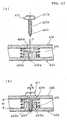
- FIG. 17 is a sectional view showing a tilt adjustment point in another configuration of the prior-art tilt adjustment mechanism.
- the portion (a) shows a state before an adjustment screw 411 is installed in a sub chassis 403 and a chassis 404
- the portion (b) shows a state wherein the adjustment screw 411 has been installed in the sub chassis 403 and the chassis 404.
- a tip portion 411t that is, the tip of the threaded portion 411n of the adjustment screw 411, is formed to have a tapered shape.
- the adjustment screw 411 shown in FIG. 17 is the so-called tapping screw having a male thread. This adjustment screw 411 is inserted into a through hole 404a in the chassis 404 and temporarily screw-locked to the through hole 403a in the chassis 403 (turning operation in the arrow direction indicated by letter F in the portion (a) of FIG. 17). Next, the adjustment screw 411 is turned (turning in the arrow directions indicated by letter R in the portion (b) of FIG.
- the tip portion 411t of the adjustment screw 411 forms a female thread inside the through hole 403a.
- the tilt adjustment mechanism shown in FIG. 17 is characterized in that it is not necessary to form a female thread in the boss portion 403b thereof in advance.
- the threaded portion 411n of the adjustment screw 411 reciprocates along the female thread portion, formed by the tapping operation, of the through hole 403a in the sub chassis 403, there is a problem of making the adjustment not easy.
- rotating the adjustment screw 411 becomes very tight, thereby causing a problem of being incapable of making smooth fine adjustment easy.
- the present invention is intended to facilitate tilt adjustment work for adjusting the movement face of the optical pickup so as to be parallel with the recording face of the optical disk and to provide an optical disk apparatus being high in reliability and capable of meeting the needs for higher speed, larger capacity and lower profile. Furthermore, the present invention is intended to make the above-mentioned adjustment work by using the tilt mechanism easy and to provide a height adjustment device capable of easily fine-adjusting the distance between the chassis and the sub chassis.
- An optical disk apparatus in accordance with the present invention comprises:
- the movement face of the optical pickup can be adjusted easily so as to be parallel] with the receiving face of the optical disk.
- An optical disk apparatus in accordance with the present invention is characterized in that the above-mentioned optical pickup comprises a lens projection portion for applying light to the optical disk and a main body for supporting the above-mentioned lens projection portion so as to be movable in the radial direction of the optical disk, and that the main face of the above-mentioned tilt chassis is disposed on the optical disk side of the above-mentioned main body.
- the movement face of the optical pickup can be adjusted easily so as to be parallel with the recording face of the optical disk, and the need for profile reduction of the apparatus can be satisfied.
- An optical disk apparatus in accordance with the present invention is characterized in that the above-mentioned tilt chassis is engaged with the above-mentioned traverse chassis so as to be contactingly movable at one adjustment support portion, that the above-mentioned tilt adjustment means comprises two tilt adjustment portions, and that the tilt adjustment portions are disposed on both sides of the movement path of the above-mentioned lens projection portion on the above-mentioned tilt chassis.
- the movement face of the optical pickup can be adjusted easily so as to be parallel with the recording face of the optical disk, and the need for profile reduction of the apparatus can be satisfied.
- An optical disk apparatus in accordance with the present invention is characterized in that the above-mentioned tilt adjustment means has an elastic member so as to absorb vibration between the above-mentioned tilt chassis and the above-mentioned traverse chassis.
- vibration from the spindle motor and the like is absorbed, whereby reading and written can be carried out securely.
- An optical disk apparatus in accordance with the present invention further comprises:
- An optical disk apparatus in accordance with the present invention further comprises:
- An optical disk apparatus in accordance with the present invention is characterized in that the above-mentioned sub shaft is integrally molded with the above-mentioned tilt chassis.
- the movement face of the optical pickup can be adjusted easily so as to be parallel with the recording face of the optical disk.
- An optical disk apparatus in accordance with the present invention is characterized in that the above-mentioned tilt adjustment means comprises two tilt adjustment portions, that the above-mentioned tilt chassis is engaged with the above-mentioned traverse chassis so as to be,contactingly movable at one adjustment support portion, that the above-mentioned adjustment support portion is disposed in the vicinity of the end of the above-mentioned main shaft on the inner circumferential side of the optical disk, that one of the tilt adjustment portions is disposed in the vicinity of the end of the above-mentioned main shaft on the outer circumferential side of the optical disk, and that the other tilt adjustment portion is disposed on the side of the above-mentioned sub shaft.
- the movement face of the optical pickup can be adjusted easily so as to be parallel with the recording face of the optical disk.
- An optical disk apparatus in accordance with the present invention is characterized in that the above-mentioned main shaft, the above-mentioned sub shaft and the above-mentioned optical pickup are configured so as to be capable of being installed on the above-mentioned tilt chassis in advance.
- the movement face of the optical pickup can be adjusted easily so as to be parallel with the recording face of the optical disk, and assembly in the production process therefor is made easy.
- An optical disk apparatus in accordance with the present invention further comprises a tilt cover disposed so as to cover the above-mentioned optical pickup, the above-mentioned main shaft and the above-mentioned sub shaft provided on the above-mentioned tilt chassis.
- a tilt cover disposed so as to cover the above-mentioned optical pickup, the above-mentioned main shaft and the above-mentioned sub shaft provided on the above-mentioned tilt chassis.
- an optical disk apparatus in accordance with the present invention is characterized in that the above-mentioned optical pickup comprises a lens projection portion for applying light to the optical disk and a main body for supporting the above-mentioned lens projection portion so as to be movable in the radial direction of the optical disk, wherein the above-mentioned main body is disposed on the optical disk side of the main face of the above-mentioned tilt chassis.
- the need for profile reduction of the apparatus can be satisfied.
- the above-mentioned optical pickup, the above-mentioned main shaft and the above-mentioned sub shaft are disposed in internal space formed by the above-mentioned tilt chassis and the above-mentioned tilt cover, wherein the above-mentioned tilt chassis and the above-mentioned tilt cover are integrally tilt-adjustable with respect to the above-mentioned traverse chassis by the above-mentioned tilt adjustment means.
- dust generating owing to air current produced by the rotation of the optical disk and adhering to the optical pickup can be reduced significantly, and the replacement of the optical pickup is made easy.
- an optical disk apparatus in accordance with the present invention is characterized in that the above-mentioned tilt chassis can be attached to and detached from the above-mentioned tilt adjustment means without changing the tilt adjustment state between the above-mentioned tilt chassis and the above-mentioned traverse chassis.
- the tilt chassis can be detached from the tilt adjustment means and separated from the traverse chassis easily, or reversely, the tilt chassis can be attached to the tilt adjustment means and installed on the traverse chassis easily while the adjustment state of the tilt adjustment means configured on the traverse chassis remains unchanged.
- the state of the tilt adjustment remains unchanged, whereby it is not necessary to reattempt tilt adjustment on each occasion.
- a height adjustment device in accordance with the present invention comprises:
- a height adjustment device in accordance with the present invention is configured so that the adjustment hole in the above-mentioned first chassis has a small diameter portion in which the female thread is formed and a large diameter portion having a diameter larger than the outside diameter of the tip portion of the above-mentioned adjustment screw and so that the above-mentioned adjustment screw is inserted from the side of the above-mentioned small diameter portion to the side of the above-mentioned large diameter portion.
- a height adjustment device in accordance with the present invention is configured so that the threaded portion of the above-mentioned adjustment screw has the same pitch as that of the tip portion and is provided with thread ridges, the diameter of which is smaller than that of the above-mentioned tip portion
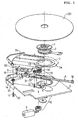
- FIG. 1 is a perspective view showing components in the vicinity of a spindle motor in an optical disk apparatus in accordance with Embodiment 1 of the present invention, taken from above (on the side of an optical disk mounted on a turntable).
- FIG. 2 is a perspective view showing the components in the vicinity of the spindle motor in the optical disk apparatus in accordance with Embodiment 1, taken from below.
- FIG. 3 is a plan view showing the upper faces of major components in the vicinity of the spindle motor in accordance with Embodiment 1.
- FIG. 4 is a rear view showing the lower faces of the major components in the vicinity of the spindle motor shown in FIG. 3.
- a turntable 1 on which an optical disk 101 is mounted is directly connected to the rotation shaft of a spindle motor 2.
- the spindle motor 2 is secured to a traverse chassis 4.
- a traverse motor 5 and a first traverse drive mechanism 10 for transmitting the driving force of the motor are provided on the rear face of this traverse chassis 4.
- the traverse chassis 4 is engaged with a tilt chassis 3 so as to be contactingly movable at an adjustment support portion 13 described later and locked at two tilt adjustment portions 30 and 31.
- the tilt chassis 3 is configured so that tilt adjustment can be carried out with respect to the traverse chassis 4 by the two tilt adjustment portions 30 and 31 serving as tilt adjustment means.
- the tilt adjustment portions 30 and 31 comprise two sets of adjustment screws 11 and 12 and springs 14 and 15. The adjustment screws 11 and 12 pass through holes 51 and 52 formed in the traverse chassis 4 and the springs 14 and 15 and are threadedly engaged with the tilt chassis 3.
- An optical pickup 50 that moves in the radial direction of the optical disk 101 mounted on the turntable 1 has an optical pickup body 8 and a lens projection portion 9 provided on the upper face (on the side of the optical disk) of the optical pickup body 8.
- the main face of the tilt chassis 3 is disposed between the upper face of the optical pickup body 8 and the lower face of the optical disk.
- the tilt chassis 3 is provided with a main shaft 6 serving as a drive guide for the optical pickup body 8 in the radial direction of the optical disk 101 and a sub shaft 7 serving as a guide shaft.
- a thread is formed on the main shaft 6, and the optical pickup body 8 engaged with this main shaft 6 is configured so as to be moved linearly by the rotation of the main shaft 6.
- the sub shaft 7 is formed so as to be integrally molded with the tilt chassis 3.
- a second traverse drive mechanism 16 engaged with the first traverse drive mechanism 10 provided on the traverse chassis 4 is provided on the tilt chassis 3.
- the driving force of the traverse motor 5 is transmitted to the main shaft 6 via the first traverse drive mechanism 10 provided on the rear face of the traverse chassis 4 and the second traverse drive mechanism 16 provided on the tilt chassis 3.
- the connection between the first traverse drive mechanism 10 and the second traverse drive mechanism 16 is disposed in the vicinity of the adjustment support portion 13 for supporting the tilt chassis 3 on the traverse chassis 4.
- This adjustment support portion 13 supports the tilt chassis 3 so as to be movably engaged with the traverse chassis 4.
- the first opening portion 3a is an opening through which the spindle motor 2 is inserted and disposed, and the turntable 1 is disposed at the upper portion thereof.
- the second opening portion 3b is formed along the movement path of the lens projection portion 9 so that the lens projection portion 9 of the optical pickup 50 can see the recording face of the optical disk 101 mounted on the turntable 1.
- FIG. 3 is a plan view showing a state wherein the spindle motor 2 and the tilt chassis 3 are installed on the traverse chassis 4 in accordance with Embodiment 1, and FIG. 4 is a rear view showing the traverse chassis 4 of FIG. 3.
- the first adjustment screw 11 and the second adjustment screw 12 of the tilt adjustment means in accordance with Embodiment 1 are provided in the vicinity of the fringe portion of the tilt chassis 3 and disposed on both sides of a straight line A including the movement path of the lens projection portion 9 of the optical pickup 50.
- the adjustment support portion 13 is formed in the vicinity of the fringe portion of the tilt chassis 3 near the center shaft of the turntable 1.
- This adjustment support portion 13 and the first adjustment screw 11 are provided in the vicinities of both ends of the main shaft 6 provided on the rear face of the tilt chassis 3, the adjustment support portion 13 is in the vicinity of the end of the main shaft 6 on the inner circumferential side of the optical disk, and the first adjustment screw 11 is in the vicinity of the end of the main shaft 6 on the outer circumferential side of the optical disk.
- the adjustment support portion 13 and the first adjustment screw 11 are disposed on the same side of the straight line A including the movement path of the lens projection portion 9 and serving as a boundary.
- the second adjustment screw 12 is disposed in the nearly intermediate portion of the sub shaft 7 provided on the rear face of the tilt chassis 3.
- the traverse motor 5 for generating a driving force to move the optical pickup 50 in the radial direction of the optical disk 101 and the first traverse drive mechanism 10 comprising a plurality of gears are provided on the rear face of the traverse chassis 4.
- the first gear (the first gear in the transmission direction of the driving force) of the second traverse drive mechanism 16 provided on the tilt chassis 3 is engaged with the last gear (the last gear in the transmission direction of the driving force) of the first traverse drive mechanism 10 in the vicinity of the adjustment support portion 13 so that the driving force can be transmitted.
- the engagement portion of the first traverse drive mechanism 10 and the second traverse drive mechanism 16 is provided in the vicinity of the adjustment support portion 13. Hence, the deviations of the engagement pitch and angle during tilt adjustment operation are very small, whereby the engagement relationship required for the transmission is attained.
- FIG. 5 is a sectional view showing the vicinity of the adjustment support portion 13.
- a support hole 4h is formed in the traverse chassis 4, and the opening end portion 4c of this support hole 4h is chamfered, that is, its corner is cut.
- the support hole 4h and the opening end portion 4c are formed coaxially.
- nearly hemispherical ball portions 3c are formed so as to protrude on both sides of the tilt chassis 3 at the position facing the opening end portion 4c, and a sphere having a diameter larger that of the opening end portion 4c is formed by the ball portions 3c formed on both sides.
- the ball portion 3c of the tilt chassis 3, facing the traverse chassis 4, makes contact with the opening end portion 4c of the traverse chassis 4.
- a pressure member 4p is secured to the traverse chassis 4, and the pressure member 4p and the opening end portion 4c hold the ball portions 3c of the tilt chassis 3 therebetween.
- the ball portion 3c of the tilt chassis 3 facing the traverse chassis 4 is pressed to the opening end portion 4c of the traverse chassis 4. Therefore, the ball portions 3c make contact with the opening end portion 4c along a nearly ring-shaped line and also make contact with the pressure member 4p at substantially one point, whereby the tilt chassis 3 is configured so as to be rotatable nearly around the center of the ball portions 3c.
- the center of the ball portions 3c of the tilt chassis 3 is disposed on the center line of the opening end portion 4c at all times. And, even if the tilt chassis is tilted, the center of the ball portions 3c is not moved in the direction of the height. Hence, the tilt chassis 3 is contactingly moved at the adjustment support portion 13, thereby being tiltable while the center of the support by the adjustment support portion 13 remains unchanged.
- FIG. 6 is a sectional view taken on line V-V of FIG. 3 and shows the configuration of the first adjustment screw 11.
- FIG. 7 is a sectional view taken on line VI-VI of FIG. 4 and shows the configuration of the second adjustment-screw 12.
- the first adjustment screw 11 passes through the hole 51 in the traverse chassis 4 and is threadedly engaged with a threaded hole 7a formed in the tilt chassis 3.
- This first adjustment screw 11 passes through the spring 14 disposed between the traverse chassis 4 and the tilt chassis 3.
- the tilt chassis 3 is pressed in the direction of being separated from the traverse chassis 4.
- the tilt chassis 3 can be adjusted to a desired angle with respect to the traverse chassis 4 around the engagement point of the adjustment support portion 13.
- the second adjustment screw 12 passes through the hole 52 in the traverse chassis 4 and is threadedly engaged with a threaded hole 7b formed in the tilt chassis 3. Furthermore, the second adjustment screw 12 passes through the spring 15 disposed between the tilt chassis 3 and the traverse chassis 4. By this spring 15, the tilt chassis 3 is pressed in the direction of being separated from the traverse chassis 4. Hence, by turning the second adjustment screw 12, the turning distance of the tilt chassis 3 can be adjusted to a desired angle with respect to the traverse chassis 4 around the engagement point of the adjustment support portion 13.
- the first adjustment screw 11 and the second adjustment screw 12 are prevented from turning by locking means, such as locking paint.
- the sub shaft 7 for guiding the optical pickup 50 in the radial direction of the optical disk 101 is formed so as to be integrated with the tilt chassis 3 and is disposed at a desired position in advance. Furthermore, the main shaft 6 for driving the optical pickup 50 is rotatably journaled at both ends thereof by bearings accurately configured on the tilt chassis 3 so as to be parallel with the center axis of the sub shaft 7 on the tilt chassis 3. Hence, in the tilt chassis 3, desired parallelism is securely attained between the center axis of the main shaft 6 and the center axis of the sub shaft 7. Therefore, the optical pickup 50 driven and guided by the main shaft 6 and the sub shaft 7 is configured so as to be securely moved along a straight line in the radial direction of the optical disk mounted on the turntable 1.
- the tilt chassis 3 on which the main shaft 6, the sub shaft 7, the optical pickup 50 and the second traverse drive mechanism 16 are disposed in advance as described above is installed on the traverse chassis 4 on which the spindle motor 2, the first traverse drive mechanism 10, etc. are provided.
- the tilt chassis 3 installed on the traverse chassis 4 is tilt-adjusted by alternately turning the first adjustment screw 11 and the second adjustment screw 12 while monitoring the output signal from the optical pickup 50.
- the tilt adjustment work in accordance with Embodiment 1 does not require such adjustment conducted by synchronous rotation at two points as described in the columns of the prior art, thereby being capable of being carried out by using simple adjustment jigs or by manual adjustment.
- the laser beam from the lens projection portion 9 of the optical pickup 50 is perpendicularly applied to the recording face of the optical disk 101 mounted on the turntable 1.
- the main shaft 6, the sub shaft 7, the optical pickup 50, etc. are disposed at the desired positions on the tilt chassis 3, and the main shaft 6 and the sub shaft 7 are disposed in parallel on the same plane in advance, whereby the above-mentioned tilt adjustment work is carried out easily. Furthermore, in the optical disk apparatus in accordance with Embodiment 1, the main shaft 6, the sub shaft 7, the optical pickup 50, etc. are disposed in advance at the desired positions on the tilt chassis 3, which is separate from the traverse chassis 4, as described above. Hence, during the tilt adjustment work, it is not necessary to secure extra space for adjustment in the apparatus in advance between the tilt chassis 3 and the optical disk 101 to be mounted.
- the main face of the tilt chassis 3 for supporting the optical pickup 50 can be secured even in the limited space between the lower face of the disk and the main body of the optical pickup 50.
- the configuration of Embodiment 1 greatly contributes to the profile reduction of the apparatus.
- the second adjustment screw 12 can also be disposed on a straight line (the straight line indicated by letter B in FIG. 3) that is orthogonal to the straight line A including the movement path of the lens projection portion 9 and passes through the center of the turntable 1.
- the adjustment work is made further easier by disposing the adjustment support position 13 on the straight line B.
- the tilt chassis 3 is configured so as to be held to the traverse chassis 4 by the springs 14 and 15.
- the tilt chassis 3 can also be configured so as to be held on the traverse chassis 4 by vibration absorbing means formed of an elastic body or the like for absorbing vibration instead of these springs 14 and 15.
- this tilt chassis since the tilt chassis for substantially covering the optical components and the drive mechanisms is provided, this tilt chassis also has a function for serving as a blind for the user and prevents fine-grain dust owing to air current produced by the rotation of the optical disk from entering the optical components and other devices. As a result, the problems of reduction in performance, impossible reproduction, etc. due to decrease in the amount of light caused by fine-grain dust adhering to and staining the optical components with the passage of long time are solved.
- the optical disk apparatus in accordance with Embodiment 1 can prevent the optical components from being stained and can attain reduction in profile, thereby having efficient effects.
- FIG. 8 is a perspective view showing components in the vicinity of a spindle motor in an optical disk apparatus in accordance with Embodiment 2 of the present invention, taken from above (on the side of an optical disk mounted on a turntable).
- FIG. 9 is a perspective view showing the components in the vicinity of the spindle motor in the optical disk apparatus in accordance with Embodiment 2, taken from below.
- FIG. 10 is a perspective view showing components in the vicinity of an optical pickup in accordance with Embodiment 2, taken from above
- FIG. 11 is a perspective view showing the components in the vicinity of the optical pickup of FIG. 10, taken from below.
- components having the same functions and configurations as those of the components of the optical disk apparatus in accordance with the above-mentioned Embodiment 1 are designated by the same numerals and their explanations are omitted.
- a turntable 1 on which an optical disk 101 is mounted is directly connected to the rotation shaft of a spindle motor 2, and the spindle motor 2 is secured to a traverse chassis 4.
- a traverse motor 5 and a first traverse drive mechanism 10 for transmitting the driving force of the motor are provided on the rear face of this traverse chassis 4.
- an optical pickup unit 200 is installed on the traverse chassis 4.
- This optical pickup unit 200 is engaged with an adjustment support portion 13 so as to be contactingly movable and locked at two points, that is, tilt adjustment portions 30 and 31.
- the optical pickup unit 200 has a tilt chassis 201 and a tilt chassis cover 202 for covering the upper face of the tilt chassis 201.
- an optical pickup 50, a main shaft 6 for driving the optical pickup 50 in the radial direction of the optical disk 101 and a sub shaft 7 serving as a guide shaft are provided inside this optical pickup unit 200.
- the optical pickup 50 comprises a lens projection portion 9 for applying light to the optical disk 101 and an optical pickup body 8 for supporting this lens projection portion 9 so as to be movable in the radial direction of the optical disk 101.
- the main face of the tilt chassis 201 is disposed on the lower side of the optical pickup body 8.
- Embodiment 2 differs from the above-mentioned Embodiment 1 in that the main shaft 6, the sub shaft 7 and the optical pickup 50 are configured so as to be enveloped with the tilt chassis 201 and the tilt chassis cover 202 in the vertical direction.
- the tilt chassis cover 202 is configured so as to be engaged with and locked to the tilt chassis 201.
- the rigidity of the tilt chassis 201 for holding various components can be raised, and air current produced by the rotation of the optical disk 101 is prevented from entering the optical components of the optical pickup 50.
- the optical pickup unit 200 is configured so as to be tilt-adjustable with respect to the traverse chassis 4 by the tilt adjustment portions 30 and 31 serving as tilt adjustment means.
- the tilt adjustment portions 30 and 31 comprise two sets of adjustment screws 11 and 12 and springs 14 and 15, and the adjustment screws 11 and 12 pass through holes 251 and 252 formed in the tilt chassis 201 and the springs 14 and 15 and are threadedly engaged with the traverse chassis 4.
- the optical pickup unit 200 is configured so as to be mounted on the rear face side of the traverse chassis 4.
- the optical pickup 50 of the optical disk apparatus it is not necessary to remove various components mounted on the upper face (the face on the side of the optical disk) of the traverse chassis 4, for example, a clamper for pressing and securing the optical disk 101 to the face of the turntable and a loading mechanism for loading the optical disk 101 on the turntable, whereby the maintenance of the optical pickup 50 is made easy in the optical disk apparatus.
- the tilt chassis 201 is provided with the main shaft 6 serving as a drive guide for the optical pickup body 8 in the radial direction of the optical disk 101 and the sub shaft 7 serving as a guide shaft.
- a thread is formed on the main shaft 6, and the optical pickup body engaged with this main shaft 6 is configured so as to be moved linearly by the rotation of the main shaft 6.
- the sub shaft 7 is formed so as to be integrally molded with the tilt chassis 201.
- a second traverse drive mechanism 16 threadedly engaged with the first traverse drive mechanism 10 provided on the traverse chassis 4 is provided on the tilt chassis 201, and the driving force of the traverse motor 5 is transmitted to the main shaft 6 via the first traverse drive mechanism 10 provided on the rear face of the traverse chassis 4 and the second traverse drive mechanism 16 provided on the tilt chassis 201.
- the connection portion between the first traverse drive mechanism 10 and the second traverse drive mechanism 16 is disposed in the vicinity of the adjustment support portion 13 that supports the tilt chassis 201 on the traverse chassis 201 while having engagement therewith.
- FIG. 10 is an exploded perspective view showing the optical pickup unit 200 of the optical disk apparatus in accordance with Embodiment 2, taken from above, and FIG. 11 is an exploded perspective view showing the optical pickup unit 200 of FIG. 10, taken from below.
- one opening portion 202a is formed in the tilt chassis cover 202.
- This opening portion 202a is formed along the movement path of the lens projection portion 9 so that the lens projection portion 9 of the optical pickup 50 can see the recording face of the optical disk 101 mounted on the turntable 1.
- the first adjustment screw 11 and the second adjustment screw 12 of the tilt adjustment means in accordance with Embodiment 2 are provided in the vicinity of the fringe portion of the tilt chassis 201 and disposed on both sides of a straight line including the movement path of the lens projection portion 9 of the optical pickup 50.
- the adjustment support portion 13 and the first adjustment screw 11 are provided in the vicinities of both ends of the main shaft 6 provided on the upper face of the tilt chassis 201, the adjustment support portion 13 is in the vicinity of the end of the main shaft 6 on the inner circumferential side of the optical disk, and the first adjustment screw 11 is in the vicinity of the end of the main shaft 6 on the outer circumferential side of the optical disk.
- the adjustment support portion 13 and the first adjustment screw 11 are disposed on the same side of a straight line including the movement path of the lens projection portion 9 and serving as a boundary.
- the second adjustment screw 12 is disposed in the nearly intermediate portion of the sub shaft 7 provided on the upper face of the tilt chassis 201.
- the second adjustment screw 12 is disposed in the nearly intermediate portion of the sub shaft 7 in Embodiment 2, an example wherein the second adjustment screw 12 is disposed in the nearly intermediate portion of the sub shaft 7 is explained.
- the second adjustment screw 12 can also be disposed on a straight line being orthogonal to the straight line including the movement path of the lens projection portion 9 and passing through the center of the turntable 1.
- the adjustment work is made further easier by disposing the adjustment support position 13 on the straight line B.
- Embodiment 2 just as in the case of the above-mentioned Embodiment 1, the first gear (the first gear in the transmission direction of the driving force) of the second traverse drive mechanism 16 provided on the tilt chassis 201 is engaged with the last gear (the last gear in the transmission direction of the driving force) of the first traverse drive mechanism 10 in the vicinity of the adjustment support portion 13.
- the engagement portion of the first traverse drive mechanism 10 and the second traverse drive mechanism 16 is provided in the vicinity of the adjustment support portion 13; hence, the deviations of the engagement pitch and angle during tilt adjustment operation are very small, whereby the engagement relationship required for the transmission is attained.
- the first adjustment screw 11 and the second adjustment screw 12 serving as the tilt adjustment means in accordance with Embodiment 2 have substantially the same configuration as that in accordance with the aforementioned Embodiment 1.
- the first adjustment screw 11 passes through the hole 251 in the tilt chassis 201 and is threadedly engaged with a threaded hole formed in the traverse chassis 4.
- This first adjustment screw 11 passes through the spring 14 disposed between the optical pickup unit 200 and the traverse chassis 4.
- the optical pickup unit 200 is pressed in the direction of being separated from the traverse chassis 4. Hence, by rotating the first adjustment screw 11, the optical pickup unit 200 can be adjusted to a desired angle with respect to the traverse chassis 4 around the engagement point of the adjustment support portion 13.
- the second adjustment screw 12 passes through the hole 252 in the tilt chassis 201 and is threadedly engaged with a threaded hole formed in the traverse chassis 4. Furthermore, the second adjustment screw 12 passes through the spring 15 disposed between the optical pickup unit 200 and the traverse chassis 4. By this spring 15, the optical pickup unit 200 is pressed in the direction of being separated from the traverse chassis 4. Hence, by turning the second adjustment screw 12, the optical pickup unit 200 can be adjusted to a desired angle with respect to the traverse chassis 4 around the engagement point of the adjustment support portion 13.
- the first adjustment screw 11 and the second adjustment screw 12 are prevented from turning by locking means, such as locking paint.
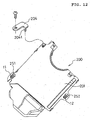
- FIG. 12 is a rear view showing the optical pickup unit 200 in accordance with Embodiment 2.
- each of the holes 251 and 252 has a shape obtained by partially superimposing a large circle and a small circle (the shape of a potbelly).
- the diameter of the large circle portion is made larger than the diameter of the head portions of the first adjustment screw 11 and the second adjustment screw 12
- the diameter of the small circle portion is made smaller than the diameter of the head portions of the first adjustment screw 11 and the second adjustment screw 12 and made larger than the threaded portions thereof. Since the holes 251 and 252 are formed as described above, by engaging the head portions of the first adjustment screw 11 and the second adjustment screw 12 with the small circle portions of the holes 251 and 252, respectively, during assembly, the optical pickup unit 200 can be held and secured to the traverse chassis 4.
- the optical pickup unit 200 After the optical pickup unit 200 is held and secured to the traverse chassis 4 as described above, tilt adjustment work is carried out. Hence, the optical pickup unit 200 can be mounted easily on the traverse chassis 4, and the tilt adjustment can be carried out. Furthermore, work for removing the optical pickup is facilitated as described later.
- the tilt adjustment work for the optical disk apparatus in accordance with Embodiment 2 is substantially the same as the tilt adjustment work in accordance with the aforementioned Embodiment 1.
- the sub shaft 7 for guiding the optical pickup 50 in the radial direction of the optical disk 101 is formed so as to be integrated with the tilt chassis 201 and is disposed at a desired position in advance. Furthermore, the main shaft 6 for driving the optical pickup 50 is rotatably journaled at both ends thereof by bearings accurately configured on the tilt chassis 201 so as to be parallel with the center axis of the sub shaft 7 on the tilt chassis 201. Hence, in the tilt chassis 201, desired parallelism is securely attained between the center axis of the main shaft 6 and the center axis of the sub shaft 7. Therefore, the optical pickup 50 driven and guided by the main shaft 6 and the sub shaft 7 is configured so as to securely move along a straight line in the radial direction of the optical disk 101 mounted on the turntable 1.
- the tilt chassis cover 202 is installed on the tilt chassis 201 on which the main shaft 6, the sub shaft 7, the optical pickup 50 and the second traverse drive mechanism 16 are disposed in advance, thereby forming the optical pickup unit 200.
- This optical pickup unit 200 is installed on the rear face of the traverse chassis 4 and tilt-adjusted by alternately turning the first adjustment screw 11 and the second adjustment screw 12 while monitoring the output signal from the optical pickup 50.
- the tilt adjustment of the optical pickup unit 200 is carried out in the tangential and radial directions by simply rotating the first adjustment screw 11 and the second adjustment screw 12 alternately. Therefore, the tilt adjustment work in accordance with Embodiment 2 does not require such adjustment conducted by synchronous rotation at two points as described in the columns of the prior art, thereby being capable of being carried out by using simple adjustment jigs or by manual adjustment.
- the laser beam from the lens projection portion 9 of the optical pickup 50 is perpendicularly applied to the recording face of the optical disk 101 mounted on the turntable 1.
- Embodiment 2 Work for removing the optical pickup from the optical disk apparatus in accordance with Embodiment 2 configured as described above will be described below.
- the configuration of the adjustment support portion between the tilt chassis 201 and the traverse chassis 4 is substantially the same as that of the adjustment support portion 13 described by using FIG. 5 in the aforementioned Embodiment 1.
- the optical pickup 50 is guided and driven by the main shaft 6 and the sub shaft 7 formed accurately on the tilt chassis 201.
- the tilt chassis 201 and the traverse chassis 4 are configured so as to be tilt-adjusted accurately by the tilt adjustment portion comprising the adjustment support portion 13, the first adjustment screw 11 and the second adjustment screw 12, serving as tilt adjustment means.
- the positional accuracy of the engagement fulcrum between the tilt chassis 3 and the traverse chassis 4 is determined by the component accuracy of the ball portions 3c formed on the tilt chassis 3, the opening end portion 4c and the support hole 4h of the traverse chassis 4.
- the positional accuracy of the engagement fulcrum can be obtained by carrying out reassembling and by applying pressure from the pressure member 4p.
- a pressure member 204 is screwed to the traverse chassis 4 so as to press a ball portion (not shown) formed on the tilt chassis 201 as shown in FIG. 9, FIG. 11 and FIG. 12.
- the first adjustment screw 11 and the second adjustment screw 12 are locked so as not to rotate by locking paint or the like as described above.
- the engagement state can be canceled by applying pressure against the biasing direction of the springs 14 and 15.
- the tilt chassis 201 is held and secured by the first adjustment screw 11 and the second adjustment screw 12 at the small circle portions of the holes 251 and 252 each formed of a large circle portion and a small circle portion connected to each other, the holding and securing by the first adjustment screw 11 and the second adjustment screw 12 can be canceled at the large circle portions of the holes 251 and 252 by sliding the tilt chassis while pressing it.
- the tilt chassis 201 can be removed from the traverse chassis 4 without rotating the first adjustment screw 11 and the second adjustment screw 12 serving as adjustment points.
- the tilt chassis 201 is held by the pressure member 204 shown in FIG. 12 at the adjustment support portion 13.
- the pressure member 204 is basically similar to the aforementioned pressure member 4p in accordance with Embodiment 1 described by using FIG. 5 and presses the ball portion formed at a predetermined position of the tilt chassis 201.
- the pressure member 204 in accordance with Embodiment 2 differs from the pressure member 4p shown in FIG. 5 in that a tab 204t is provided and that this tab 204t is inserted into a dent portion 201m formed in the tilt chassis 201 while having a gap therein.
- the optical pickup unit 200 cannot slide because of the engagement between the tab 204t and the dent portion 201m, unless the pressure member 204 is disengaged from the traverse chassis 4. Furthermore, even if the optical pickup unit 200 should be likely to slide owing to the decrease in the biasing forces of the springs 14 and 15 of the tilt adjustment portion owing to vibration or the like, the tab 204t of the pressure member 204 engages the dent portion 201m, thereby preventing sliding. Still further, the tab 204t is loosely inserted into the dent portion 201m while having a predetermined gap so as not to make contact therewith in the range of the tilt adjustment, whereby the tilt adjustment work is not hindered.
- the optical pickup unit 200 is configured so as to be held to the traverse chassis 4 by the springs 14 and 15; however, the optical pickup unit 200 can also be configured so as to be held to the traverse chassis 4 by vibration absorbing means formed of an elastic body or the like for absorbing vibration instead of these springs 14 and 15.
- the main shaft 6, the sub shaft 7, the optical pickup 50, etc. are disposed at the desired positions inside the optical pickup unit 200, and the main shaft 6 and the sub shaft 7 are disposed in parallel on the same plane in advance, whereby the above-mentioned tilt adjustment is carried out easily. Furthermore, in the optical disk apparatus in accordance with Embodiment 2, the main shaft 6, the sub shaft 7, the optical pickup 50, etc. are disposed in advance at the desired positions on the optical pickup unit 200, which is separate from the traverse chassis 4, as described above; hence, during the tilt adjustment work, it is not necessary to secure extra space for adjustment in the apparatus in advance between the optical pickup unit 200 and the optical disk 101 to be mounted, thereby greatly contributing to the profile reduction of the apparatus.
- this tilt chassis cover 202 since the tilt chassis cover 202 for substantially covering the optical components and the drive mechanisms is provided, this tilt chassis cover 202 also has a function for serving as a blind for the user. Furthermore, in the optical disk apparatus in accordance with Embodiment 2, since the optical pickup body 8 is accommodated inside the optical pickup unit 200, fine-grain dust owing to air current produced by the rotation of the optical disk 101 is prevented from entering the optical components and other devices. As a result, the problems of reduction in performance, impossible reproduction, etc. due to decrease in the amount of light caused by dust adhering to and staining the optical components inside the optical pickup body 8 with the passage of long time are solved.
- Embodiment 3 a height adjustment device in an optical disk apparatus in accordance with Embodiment 3 of the present invention will be described by using the accompanying FIG. 13.
- the height adjustment device that is described in Embodiment 3 is used for the tilt adjustment of the optical disk apparatus and is also applicable as a height adjustment device for adjusting the distance (height) between a chassis and a sub chassis for use in general electric appliances.
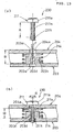
- FIG. 13 is a sectional view showing the configuration of the height adjustment device in the optical disk apparatus in accordance with Embodiment 3 of the present invention.
- the portion (a) shows a state before an adjustment screw 211 is installed in a sub chassis 203 and a chassis 204
- the portion (b) shows a state wherein the adjustment screw 211 is installed in the sub chassis 203 and the chassis 204.
- the sub chassis and the chassis correspond to the tilt chassis and the traverse chassis in accordance with the above-mentioned embodiments, and the distance (height) between the sub chassis and the chassis is adjusted by the height adjustment device.
- the chassis 204 and the sub chassis 203 are disposed so as to face each other, and the distance therebetween is adjusted by a height adjustment device 230 as described below.
- the adjustment screw is indicated so as to be inserted into the chassis 204 and the sub chassis 203 from above.
- a boss portion 203b protruding toward the chassis 204 is formed on the sub chassis 203.
- An adjustment hole 203a is formed in this boss portion 203b, a female thread 203s is formed during an assembly process by the adjustment screw 211 as described later.
- a through hole 204a is formed in the chassis 204 disposed so as to have a predetermined distance from the sub chassis 203. The adjustment screw 211 is inserted into and passed through this through hole 204a and screwed into the adjustment hole 203a.
- An adjustment spring 214 is provided between the sub chassis 203 and the chassis 204 in the vicinity of the adjustment screw 211 to be installed.
- this adjustment spring 214 is the so-called helical spring, and the adjustment screw 211 is configured so as to pass through the substantial center of the helical spring.
- the adjustment spring 214 that is, a helical spring
- the diameter of the boss portion 203b is made slightly smaller than the diameter of the spring.
- the adjustment spring 214 is disposed so as to be held between the sub chassis 203 and the chassis 204, whereby the sub chassis 203 and the chassis 204 are biased in the direction of being separated from each other. Hence, the chassis 204 is locked by the head portion 211a of the adjustment screw 211 that is screwed into the adjustment hole 203a in the sub chassis 203, whereby the distance (height) between the sub chassis 203 and the chassis 204 is determined. Since the boss portion 203b of the sub chassis 203 is configured so as to be inserted into the adjustment spring 214 as described above, a portion (a threaded portion 203n) threaded inside the adjustment hole 203a can securely have a length required for the engagement with the adjustment screw 211. Furthermore, since the boss portion 203b is a protrusion, the adjustment spring 214 can be assembled easily at its predetermined position during the assembly process.
- Embodiment 3 differs from those of the prior-art adjustment devices described above and shown in FIG. 16 and FIG. 17 in the screw configuration of the adjustment screw 211 and the configuration of the adjustment hole 203a in the sub chassis, 203 for receiving the adjustment screw.
- the diameter of the head portion 211a is formed so as to be larger than the diameter of the through hole 204a in the chassis 204, and the tip portion 211t of the adjustment screw 211 has the shape of a male thread for forming a female thread in the adjustment hole 203a in the sub chassis 203.
- a threaded portion 211n formed below the head portion 211a of the adjustment screw 211 has a thread having the same pitch as that of the male thread of the tip portion 211t, and its diameter is made slightly smaller than the diameter of the tip portion 211t.
- the adjustment screw 211 in accordance with Embodiment 3 comprises the head portion 211a, the threaded portion 211n and the tip portion 211t.
- the threaded portion 211n is a portion having ordinary thread ridges having the same diameter.
- the tip portion 211t has a tapping screw for forming a female thread and is formed of at least one thread ridge having a diameter slightly larger than the diameter of the threaded portion 211n.
- ALMITITE registered trademark of NITTO SEIKO CO., LTD., devised as a tapping screw to be screwed into a soft material and disclosed in Japanese Unexamined Utility Model Publication No. Hei 8-1340 (Japanese Utility Model Application No. Hei 8-1821), and the like are available.
- the adjustment hole 203a having a step is formed in the boss portion 203b formed on the sub chassis 203 so as to protrude toward the chassis.
- a small diameter portion 203s being small in inside diameter is formed on the side into which the adjustment screw 211 is inserted, and a large diameter portion 203d being large in inside diameter is formed on the opposite side.
- the adjustment hole 203a is a through hole having the small diameter portion 203s and the large diameter portion 203d, and the step is formed in its internal face.
- the small diameter portion 203s of the adjustment hole 203a is formed so as to have a diameter nearly identical to that of the root of the male thread of the adjustment screw 211 so that the female threaded portion 203n is formed as shown in the portion (b) of FIG. 13 when the tip portion 211t of the adjustment screw 211 is screwed therein.
- the large diameter portion 203d of the adjustment hole 203a is made larger than the maximum outside diameter portion of the tip portion 211t of the adjustment screw 211.
- the distance B from the chassis-side end of the large diameter portion 203d of the adjustment hole 203a to the upper face (the face of the chassis 204 making contact with the head portion 211a of the adjustment screw 211) of the chassis 204 is made shorter than the length A of the threaded portion 211n of the adjustment screw 211.
- the length A of the threaded portion 211n of the adjustment screw 211 is made longer than the distance B obtained at the time of height adjustment.
- the adjustment spring 214 is inserted over the boss portion 203b of the sub chassis 203, and the chassis 204 is disposed at a predetermined position with respect to the sub chassis 203.
- the adjustment screw 211 including the tip portion 211t having a tapping screw is passed through the through hole 204a in the chassis 204 and screwed into the adjustment hole 203a in the sub chassis 203 (in the direction of arrow F of FIG. 13).
- the tip portion 211t of the adjustment screw 211 has a tapping screw, the tip portion 211t forms a female thread in the small diameter portion 203s of the adjustment hole 203a.
- the tip portion 211t of the adjustment screw 211 passes through while forming the female thread in the small diameter portion 203s and then reaches the large diameter portion 203d.
- the adjustment screw 211 is turned (in the directions indicated by arrows R in the position (b) of FIG. 13). Since the threaded portion 211n of the adjustment screw 211 is slightly thinner than the female thread formed by the male thread of the tip portion 211t, smooth engagement is attained between the threaded portion 211n of the adjustment screw 211 and the threaded portion 203n of the boss portion 203b, whereby smooth rotation can be carried out without causing rattling during the above-mentioned adjustment operation.
- the length A of the threaded portion 211n of the adjustment screw 211 is configured so as to be made longer than the distance B obtained at the time of the height adjustment as described above.
- the length A of the threaded portion 211n is made longer than the sum of the thickness of the chassis 204, the face-to-face distance (including a variation tolerance) from the sub chassis 203 (the main plane thereof) to the chassis 204 and the design distance from the above-mentioned main plane of the sub chassis 203 to the step (the boundary of the small diameter portion 203s. and the large diameter portion 203d) of the adjustment hole 203a.
- the tip portion 211t of the adjustment screw 211 is disposed in the large diameter portion 203d at all times, thereby not engaging the small diameter portion 203s.
- the rotation of the adjustment screw 211 does not become heavy, whereby smooth adjustment work can be carried out at all times.
- the height of the head portion 211a of the adjustment screw 211 is adjusted by the engagement between the threaded portion 211n of the adjustment screw 211 and the threaded portion 203n of the small diameter portion 203s during the adjustment operation. Since the sub chassis 203 and the chassis 204 are biased so as to be separated from each other by the adjustment spring 214, the distance (height) between the sub chassis 203 and the chassis 204 is determined.
- the adjustment screw 211 is locked by using locking paint or the like to prevent rotation.
- the locking paint by applying the locking paint to the space between the large diameter portion 203d and the tip portion 211t, an adhesion area can be obtained sufficiently, whereby highly reliable adhesion and locking are made possible.
- the adjustment screw 211 is provided with the threaded portion 211n, that is, an ordinary male threaded portion, and the tip portion 211t for forming a female thread, and the length of the small diameter portion 203s of the sub chassis 203 is set at a length obtained from the maximum separation distance obtained during the height adjustment operation.
- the adjustment device in accordance with Embodiment 3 it is not necessary to form a female thread in the adjustment hole in the sub chassis 203 in advance.
- the tip portion 211t of the adjustment screw 211 does not make contact with the small diameter portion 203s, whereby the rotation of the adjustment screw 211 is smooth and fine-adjustment can be carried out easily.
- Embodiment 3 is configured so that the adjustment hole 203a in the sub chassis 203 has the small diameter portion 203s and the large diameter portion 203d; however, the adjustment device in accordance with the present invention is not necessarily limited to this kind of configuration. For example, it may be possible to use a configuration wherein no large diameter portion is formed in the adjustment hole and the tip portion of the adjustment screw protrudes completely from the rear face of the sub chassis or is exposed outside at the time of the adjustment work.
- Embodiment 3 an example wherein the boss portion 203b is formed on the sub chassis 203 so as to protrude toward the chassis is described; however, if the sub chassis has a thickness enough to be able to form a female thread, it is not necessary to provide the boss portion. In addition, even if it is necessary to provide the boss portion on the sub chassis, the boss portion may be provided on the opposite side not facing the chassis.
- a portion (a non-threaded portion) with no male thread and having the same diameter as the outside diameter (the diameter of the thread ridges) of the threaded portion 211n may be formed between the head portion 211a and the threaded portion 211n of the adjustment screw 211.
- the length of this non-threaded portion is set as equal as the thickness of the chassis 204.
- adjustment can be carried out easily and securely so that the movement face of the optical pickup becomes parallel with the recording face of the optical disk, whereby a highly reliable optical disk apparatus can be provided.
- the tilt chassis is provided with the main shaft, the sub shaft and the optical pickup at their desired positions in advance, and the tilt chassis is configured so as to be installed on the traverse chassis and tilt-adjusted.
- the present invention can provide a highly reliable optical disk apparatus at low production cost.
- the tilt chassis is provided and the opening portion is formed only at the portion along the movement path of the optical pickup, whereby air current produced by the rotation of the optical disk hardly enters the optical pickup body; therefore, dust generated owing to the air current produced by the rotation of the optical disk and adhering to the optical components inside the optical pickup is reduced significantly, whereby the reliability of the apparatus can be raised.
- connection portion from the first traverse driving means of the traverse chassis to the second traverse driving means of the tilt chassis is provided in the vicinity of the adjustment support portion for the tilt chassis and the traverse chassis, the connection portion between the first traverse driving means and the second traverse driving means is maintained in a state of being capable of securely transmitting the driving force even when the tilt adjustment work is carried out.
- the tilt chassis that holds the main shaft, the sub shaft and the optical pickup is provided with the optical pickup unit equipped with the tilt chassis cover, the rigidity of the tilt chassis holding various components can be raised, and air current produced by the rotation of the optical disk is prevented from entering the optical components of the optical pickup.
- the tilt adjustment operation can be carried out easily, and the optical components are prevented from being stained, whereby it is possible to provide a highly reliable optical disk apparatus.
- the optical pickup unit is configured so as to be installed on the rear face side of the traverse chassis, it is possible to provide an optical disk apparatus being maintained easily.
- the height adjustment device in accordance with the present invention it is not necessary to form a female thread in the adjustment hole in the sub chassis in advance. Moreover, during the adjustment operation, unsmooth adjustment due to heavy rotation of the adjustment screw does not occur, whereby fine-adjustment can be carried out accurately.
- an optical disk apparatus for reproducing form an optical disk on which information has been recorded and for recording information on an optical disk
- tilt adjustment work for adjusting the movement face of an optical pickup so as to be parallel with the recording face of the optical disk is made easy, whereby an optical disk apparatus and a height adjustment device being high in reliability and low in profile are provided.
Landscapes
- Moving Of The Head For Recording And Reproducing By Optical Means (AREA)
Abstract
In an optical disk apparatus in accordance
with the present invention, a tilt chassis (3, 201) to
which a main shaft (6) and a sub shaft (7), being
parallel with each other and serving to guide the
movement direction of an optical pickup (50), are
secured is disposed rotatably with respect to a
traverse chassis (4) to which a spindle motor (2) is
secured, and the tilt chassis (3, 201) is configured
so as to be tilt-adjustable with respect to the
traverse chassis (4) by tilt adjustment means having
two tilt adjustment portions (30, 31), whereby tilt
adjustment work for adjusting the movement face of the
optical pickup so as to be parallel with the recording
face of an optical disk is made easy.
Description
The present invention relates to an optical
disk apparatus for reproducing from back an optical
disk on which information has been recorded and for
recording information on an optical disk and to a
height adjustment device, and more particularly to a
tilt adjustment mechanism in an optical disk apparatus
for adjusting the tilt of an optical disk mounted on a
turntable with respect to the movement face of an
optical pickup.
In a prior-art optical disk apparatus, when
information recorded on an optical disk is reproduced
by an optical pickup or when information is recorded
on an optical disk by the optical disk, the optical
axis of a laser beam from the optical pickup is set so
as to be perpendicular to the recording face of the
optical disk. If the optical axis of the laser beam
tilts with respect to the recording face of the
optical disk, there is a problem of being unable to
accurately carry out recording or reproducing on the
optical disk. Conventionally, various tilt adjustment
mechanisms for adjusting the tilt of the optical axis
are provided for optical disk apparatuses. In
particular, high-density optical disks have become to
be used, since optical apparatuses have been made
higher in speed and larger in capacity in recent years,
whereby the accuracy of recording/reproducing has
become requested to be strict. Hence, the tilt
adjustment mechanism for adjusting the relative angle
between the optical axis of the optical pickup and the
optical disk has become an important mechanism.
Furthermore, since the optical disk apparatus is
earnestly requested for reduction in profile, a
compact head capable of meeting the need for the
reduction in profile has begun to be used; hence the
tilt adjustment mechanism is also requested to be
capable of meeting the need for further reduction in
profile.
In response to such requests for higher
speed, larger capacity and lower profile in optical
disk apparatuses, various tilt adjustment mechanisms
have been developed. As prior-art tilt adjustment
mechanisms, devices disclosed in Japanese Unexamined
Patent Publication No. Hei 9-320214 and Japanese
Unexamined Patent Publication No. Hei 10-208372 are
available, for example.
FIG. 14 is a plan view showing a tilt
adjustment mechanism in an optical disk apparatus
disclosed in Japanese Unexamined Patent Publication No.
Hei 9-320214. In FIG. 14, an optical pickup 102 for
emitting laser beam to an optical disk 101 is
installed between a first guide shaft 103 and a second
guide shaft 104 being adjusted in advance so as to be
parallel with each other. A first adjustment member
105A and a second adjustment member 105B are provided
at both ends of the first guide shaft 103. A third
adjustment member 105C and a support member 106 are
provided at both ends of the second guide shaft 104.
The first to third adjustment members 105A, 105B and
105C are provided with rotation members 108A, 108B and
108C being rotatable with respect to the chassis and
also provided with cams 109A, 109B and 109C protruding
on the upper faces of these rotation members 108A,
108B and 108C and serving as bearings for the first
guide shaft 103 or the second guide shaft 104. These
cams 109A, 109B and 109C are configured so that their
heights change gradually depending on the rotation
angles of the rotation members 108A, 108B and 108C.
Hence, by rotating the rotation members 108A, 108B and
108C, the cams 109A, 109B and 109C are rotated,
whereby the ends of the first guide shaft 103 and the
second guide shaft 104, corresponding thereto
respectively, are moved up and down.
In addition, in the vicinities of the
rotation members 108A, 108B and 108C, the vicinities
of the ends of the first guide shaft 103 and the
second guide shaft 104 are supported by U-shaped
fittings 107A, 107B and 107C secured to the chassis so
as to be movable only upward. Furthermore, the
vicinities of the ends of the first guide shaft 103
and the second guide shaft 104 are pressed downward
elastically by pressure springs 110A, 110B and 110C.
Moreover, the support member 106 rotatably supports
one end of the second guide shaft 104.
In the prior-art optical disk apparatus
configured as described above and disclosed in
Japanese Unexamined Patent Publication No. Hei 9-320214,
the rotation members 108A, 108B and 108C and
the cams 109A, 109B and 109C, serving as adjustment
members, are formed to have the same shapes,
respectively. Hence, by rotating the rotation members
108A, 108B and 108C by the same angle, the support
points corresponding to the first guide shaft 103 and
the second guide shaft 104 are configured so as to be
moved by the same height. For this reason, the
components of the adjustment members 105A, 105B and
105C are required to be made with high accuracy. The
distortion and tilt of the plane including the center
axis of the first guide shaft 103 and the center axis
of the second guide shaft 104 are adjusted by using
the three adjustment members 105A, 105B and 105C.
In other words, in the tilt adjustment of
this prior-art optical disk apparatus, it is necessary
to adjust the movement face of the optical pickup 102
while the parallelism between the center axis of the
first guide shaft 103 and the center axis of the
second guide shaft 104 is maintained at all times.
Therefore, the parallelism between the center axis of
the first guide shaft 103 and the center axis of the
second guide shaft 104 is adjusted in advance, and the
adjustment members 105A and 105B are moved
synchronously by the same amount, and then the
adjustment members 105B and 105C are moved
synchronously by the same amount. By repeating these
adjustment operations, the optical pickup 102 is
disposed so as to take an optimal movement path.
Hence, in this prior-art optical disk apparatus,
synchronous adjustment processes at a plurality of
points are required a plurality of times so that the
recording face of the optical disk 101 becomes
parallel with the movement face of the optical pickup
102. In this synchronous adjustment process, two of
the plurality of points are required to be rotated and
adjusted synchronously; hence, manual adjustment is
difficult, whereby it is necessary to use jigs or
adjustment devices specially intended for the purpose.
In the prior-art optical disk apparatus
configured as described above, the components of the
adjustment members of the optical disk apparatus
disclosed in Japanese Unexamined Patent Publication No.
Hei 9-320214 are required to be made with high
accuracy, and special devices are required to be used
for the tilt adjustment in the production process
thereof. This results in causing a problem of
increasing production cost. Since this prior-art
optical disk apparatus is configured so that the
movement face of the optical pickup is adjusted by
using the adjustment members disposed at the three
points, the adjustment process is required a plurality
of times, whereby complicated adjustment work is
necessary. Furthermore, air current produced by the
rotation of the optical disk flows through the space
in which the optical pickup is disposed, fine-grain
dust adheres to the optical components thereof, and
the amount of light decreases during a long period of
use, thereby causing reduction in performance or
falling into impossible reproduction in the worst case.
FIG. 15 is a side sectional view showing the
vicinity of the spindle motor installation portion of
the prior-art optical disk apparatus disclosed in
Japanese Unexamined Patent Publication No. Hei 10-208372.
In FIG. 15, a spindle motor 112, the rotation
shaft of which is secured to a turntable 111, is
installed on the upper face of a support plate 113. A
first locking screw 115 passes through a first spring
115A disposed between a locking board 114 for
supporting the entire apparatus and the support plate
113 and is threadedly engaged with the threaded
portion of the support plate 113. Hence, the support
plate 113 is biased by the first spring 115A in the
direction of being separated from the locking board
114. In addition, just like the first locking screw
115, a second locking screw 116 passes through a
second spring 116A disposed between the locking board
114 and the support plate 113 and is threadedly
engaged with the threaded portion of the support plate
113. Hence, the support plate 113 is biased by the
second spring 116A in the direction of being separated
from the locking board 114. The first locking screw
115 and the second locking screw 116 are provided at
positions away from the same distance from the center
axis of an optical disk mounted on the turntable 111.
A hemispherical convex portion 117
protruding downward is formed on the lower face of the
support plate 113. The hemispherical face of this
convex portion 117 is formed on an arc, the center of
which is located at a point 111b wherein a disk
mounting face 111a is orthogonal to the center of the
rotation shaft of the spindle motor 112. On the upper
face of the locking board 114, three small
hemispherical protrusions 118, protruding upward, are
formed. These protrusions 118 are disposed so as to
support the hemispherical convex portion 117 at three
points.
Next, tilt adjustment work in the apparatus
disclosed in Japanese Unexamined Patent Publication No.
Hei 10-208372 configured as described above will be
described.
First, when the first locking screw 115
threadedly engaged with the support plate 113 is
rotated, the support plate 113 is turned and displaced
along the shape of the hemispherical convex portion
117. As a result, the spindle motor 112 and the
turntable 111 can be tilted in the radial direction of
the tracks of the optical disk.
Next, when the second locking screw 116
threadedly engaged with the support plate 113 is
rotated, the support plate 113 is turned and displaced
along the shape of the hemispherical convex portion
117. As a result, the spindle motor 112 and the
turntable 111 can be tilted in the tangential
direction of the tracks of the optical disk.
By rotating the first locking screw 115 and
the second locking screw 116 as described above, tilt
adjustment can be carried out so that the disk
mounting face 111a becomes orthogonal to the optical
axis of the optical pickup.
In the optical disk apparatus configured as
described above and disclosed in Japanese Unexamined
Patent Publication No. Hei 10-208372, the spindle
motor and the turntable are directly turned with
respect to the movement face of the optical pickup
during the tilt adjustment operation. Hence, the
configuration of this optical disk apparatus is
required to secure space for vertical adjustment of
the optical disk mounted on the turntable, thereby
hindering profile reduction of the apparatus. The
optical disk apparatus disclosed in Japanese
Unexamined Patent Publication No. Hei 10-208372 is
configured so that the spindle motor for rotating the
optical disk is supported by the springs 115A and 116A
serving as the tilt adjustment members. Because of
this configuration, in the case when an unbalanced
optical disk is mounted and rotated, the spindle motor
portion may resonate, thereby causing a danger of
producing vibration, such as swinging, resulting in
adversely affecting devices.
Next, specific examples of prior-art tilt
adjustment members are taken and their problems will
be described.
In an optical disk apparatus, information is
recorded by applying laser beam to an optical disk and
by changing the state of the optical disk. In
addition, recorded information is reproduced on the
basis of the difference in the reflection of the laser
beam due to the difference in the state of the
recording face of the optical disk. Hence, the laser
beam emitted from the optical pickup is required to be
applied accurately so as to be orthogonal to the
recording face of the optical disk without changing
the shape of the spot light thereof. Therefore, in
the production process of the optical disk apparatus,
it is necessary to accurately adjust the application
angle of the laser beam to the optical disk while the
laser beam emitted from the optical pickup is applied
to the recording face of the optical disk. In this
adjustment process, the relationship in height between
the optical disk mounting face of the turntable
rotating with the optical disk mounted thereon (or a
chassis rotatably supporting this turntable) and the
movement face of the optical pickup by the movement
mechanism of the optical pickup (or a sub chassis
supporting this movement mechanism) is adjusted.
Furthermore, the parallelism between the reference
planes of the chassis and the sub chassis is adjusted
so as to be within predetermined accuracy in the
production process of the optical disk apparatus.
Apparatuses wherein such a relationship in
height is required to be adjusted accurately are not
limited to optical disk apparatuses. For example, in
magnetic recording/reproducing apparatuses, such as
video tape recorders (VTRs), the positional
relationship between a rotation head drum on which
tape serving as a recording medium is wound askew so
as to carry out helical recording thereon and the
traveling tape, the positional relationships among a
plurality of magnetic heads provided inside the
rotation head drum relative to the tape, etc. are also
required to be adjusted similarly.
The chassis supporting the turntable and the
sub chassis supporting the movement mechanism,
described above, are generally configured so as to be
supported at three points. In the case when the
parallelism between the reference plane of the chassis
and the reference plane of the sub chassis is adjusted,
one of the three support points is used as an engaged
movable fulcrum, and the heights (distances) at the
other two points are made adjustable, and then the
above-mentioned tilt adjustment should be carried out.
FIG. 16 is a sectional view showing the
configuration of the adjustment point of a prior-art
tilt adjustment mechanism configured as described
above. In FIG. 16, the portion (a) shows a state
before an adjustment screw 311 is installed in a sub
chassis 303 and a chassis 304, and the portion (b)
shows a state wherein the adjustment screw 311 has
been installed in the sub chassis 303 and the chassis
304.
In FIG. 16, a threaded hole 303a having a
female thread 303n into which the adjustment screw 311
is tightened is formed in the sub chassis 303. The
chassis 304 is disposed so that its height (separation
distance) is adjusted with respect to the sub chassis
303, and the adjustment screw 311 inserted into a
through hole 304 formed in the chassis 304 is
threadedly engaged with the threaded hole 303a formed
in the sub chassis 303. An adjustment spring 314 is
disposed in the vicinity of the threaded hole 303a and
held between the sub chassis 303 and the chassis 304.
Hence, the chassis 304 is biased in the direction of
being separated from the sub chassis 303 and locked by
the head portion 311a of the adjustment screw 311,
whereby the distance (the separation distance) between
the chassis 304 and the sub chassis 303 is determined.
In this example, the adjustment spring 314 is the so-called
helical spring, and the adjustment screw 311 is
disposed so as to pass through the helical spring.
Hence, a boss portion 303b, in which the threaded hole
303a is formed, is formed to have a diameter slightly
smaller than the diameter of the spring so as to be
insertable into the helical spring. Because of this
configuration, the female thread 303n can be formed so
as to be long in the sub chassis 303, whereby the
portion tightened by the screw is made long and the
assembly work for the adjustment spring 314 is made
easy.
The operation of the prior-art tilt
adjustment mechanism configured as described above
will be described below.
First, the adjustment spring 314 is inserted
over the boss portion 303b of the sub chassis 303.
Next, the chassis 304 is disposed at a predetermined
position, and the adjustment screw 311 is passed
through a through hole 304a in the chassis 304 and
temporarily screw-locked into the threaded hole 304a
in the chassis 304 (turning operation in the arrow
direction indicated by letter F in the portion (a) of
FIG. 16). Next, the adjustment screw 311 is turned
(turning in the arrow directions indicated by letter R
in the portion (b) of FIG. 16) so that the adjustment
screw 311 is threadedly engaged with the female thread
303n in the threaded hole 303a thereby to adjust the
distance between the sub chassis 303 and the chassis
304. By this thread engagement operation, the
position of the head portion 311a of the adjustment
screw 311 is moved with respect to the sub chassis 303,
whereby the position of the chassis 304 (the
separation distance: the distance indicated by letter
M in the portion (b) of FIG. 16) biased by the
adjustment spring 314 so as to be separated is
determined.
After the tilt adjustment is completed as
described above, the adjustment screw 311 is locked by
a screw locking treatment by using locking paint, for
example, so as not to rotate, whereby the rotation of
the adjustment screw 311 is prevented and the height
of the head portion 311a remains unchanged.
However, in the above-mentioned prior-art
tilt adjustment mechanism, the female thread 303n is
required to be formed in advance at the predetermined
position of the boss portion 303b of the sub chassis
303, thereby having a problem of increasing machining
cost. In addition, if the backlash between the thread
portion 311n of the adjustment screw 311 and the
female thread 303n of the boss portion 303b is large,
there is a problem of lowering the accuracy of the
adjustment. On the other hand, if the clearance is
made smaller so that the backlash between the threaded
portion 311n of the adjustment screw 311 and the
female thread 303n of the boss portion 303b is made
smaller, the rotation of the adjustment screw 311
becomes heavy, thereby causing a problem of making the
adjustment work difficult. If an attempt is made to
suitably set the clearance, variations in the
machining accuracy of the female thread 303n of the
sub chassis 303 and the quality of the adjustment
screw 311 are required to be eliminated.
As a tilt mechanism for solving the problems
in the above-mentioned prior-art tilt adjustment
mechanism shown in FIG. 16, a mechanism shown in FIG.
17 is available. FIG. 17 is a sectional view showing
a tilt adjustment point in another configuration of
the prior-art tilt adjustment mechanism. In FIG. 17,
the portion (a) shows a state before an adjustment
screw 411 is installed in a sub chassis 403 and a
chassis 404, and the portion (b) shows a state wherein
the adjustment screw 411 has been installed in the sub
chassis 403 and the chassis 404.
As shown in FIG. 17, no threaded portion is
formed in a through hole 403a in the sub chassis 403,
and a tip portion 411t, that is, the tip of the
threaded portion 411n of the adjustment screw 411, is
formed to have a tapered shape. The adjustment screw
411 shown in FIG. 17 is the so-called tapping screw
having a male thread. This adjustment screw 411 is
inserted into a through hole 404a in the chassis 404
and temporarily screw-locked to the through hole 403a
in the chassis 403 (turning operation in the arrow
direction indicated by letter F in the portion (a) of
FIG. 17). Next, the adjustment screw 411 is turned
(turning in the arrow directions indicated by letter R
in the portion (b) of FIG. 17) to adjust the distance
between the sub chassis 403 and the chassis 404, while
the adjustment screw 411 is engaged with the through
hole 403a. By this engagement operation, the position
of the head portion 411a of the adjustment screw 411
is moved with respect to the sub chassis 403, whereby
the position of the chassis 404 (the separation
distance: the distance indicated by letter M in the
portion (b) of FIG. 17) biased by the adjustment
spring 414 so as to be separated is determined.
By screwing the adjustment screw 411 into
the through hole 403a in the sub chassis 403 as
described above, the tip portion 411t of the
adjustment screw 411 forms a female thread inside the
through hole 403a.
The tilt adjustment mechanism shown in FIG.
17 is characterized in that it is not necessary to
form a female thread in the boss portion 403b thereof
in advance. However, in the tilt adjustment, since
the threaded portion 411n of the adjustment screw 411
reciprocates along the female thread portion, formed
by the tapping operation, of the through hole 403a in
the sub chassis 403, there is a problem of making the
adjustment not easy. In other words, in the tilt
adjustment, when the tip portion 411t of the
adjustment screw 411 is inserted into the through hole
403a, rotating the adjustment screw 411 becomes very
tight, thereby causing a problem of being incapable of
making smooth fine adjustment easy.
In order to solve various problems in the
above-mentioned prior art, the present invention is
intended to facilitate tilt adjustment work for
adjusting the movement face of the optical pickup so
as to be parallel with the recording face of the
optical disk and to provide an optical disk apparatus
being high in reliability and capable of meeting the
needs for higher speed, larger capacity and lower
profile. Furthermore, the present invention is
intended to make the above-mentioned adjustment work
by using the tilt mechanism easy and to provide a
height adjustment device capable of easily fine-adjusting
the distance between the chassis and the sub
chassis.
An optical disk apparatus in accordance with
the present invention comprises:
In the optical disk apparatus configured as
described above, the movement face of the optical
pickup can be adjusted easily so as to be parallel]
with the receiving face of the optical disk.
An optical disk apparatus in accordance with
the present invention is characterized in that the
above-mentioned optical pickup comprises a lens
projection portion for applying light to the optical
disk and a main body for supporting the above-mentioned
lens projection portion so as to be movable
in the radial direction of the optical disk, and that
the main face of the above-mentioned tilt chassis is
disposed on the optical disk side of the above-mentioned
main body. In the optical disk apparatus
configured as described above, the movement face of
the optical pickup can be adjusted easily so as to be
parallel with the recording face of the optical disk,
and the need for profile reduction of the apparatus
can be satisfied.
An optical disk apparatus in accordance with
the present invention is characterized in that the
above-mentioned tilt chassis is engaged with the
above-mentioned traverse chassis so as to be
contactingly movable at one adjustment support portion,
that the above-mentioned tilt adjustment means
comprises two tilt adjustment portions, and that the
tilt adjustment portions are disposed on both sides of
the movement path of the above-mentioned lens
projection portion on the above-mentioned tilt chassis.
In the optical disk apparatus configured as described
above, the movement face of the optical pickup can be
adjusted easily so as to be parallel with the
recording face of the optical disk, and the need for
profile reduction of the apparatus can be satisfied.
An optical disk apparatus in accordance with
the present invention is characterized in that the
above-mentioned tilt adjustment means has an elastic
member so as to absorb vibration between the above-mentioned
tilt chassis and the above-mentioned
traverse chassis. In the optical disk apparatus
configured as described above, vibration from the
spindle motor and the like is absorbed, whereby
reading and written can be carried out securely.
An optical disk apparatus in accordance with
the present invention further comprises:
An optical disk apparatus in accordance with
the present invention further comprises:
An optical disk apparatus in accordance with
the present invention is characterized in that the
above-mentioned sub shaft is integrally molded with
the above-mentioned tilt chassis. In the optical disk
apparatus configured as described above, the movement
face of the optical pickup can be adjusted easily so
as to be parallel with the recording face of the
optical disk.
An optical disk apparatus in accordance with
the present invention is characterized in that the
above-mentioned tilt adjustment means comprises two
tilt adjustment portions, that the above-mentioned
tilt chassis is engaged with the above-mentioned
traverse chassis so as to be,contactingly movable at
one adjustment support portion, that the above-mentioned
adjustment support portion is disposed in
the vicinity of the end of the above-mentioned main
shaft on the inner circumferential side of the optical
disk, that one of the tilt adjustment portions is
disposed in the vicinity of the end of the above-mentioned
main shaft on the outer circumferential side
of the optical disk, and that the other tilt
adjustment portion is disposed on the side of the
above-mentioned sub shaft. In the optical disk
apparatus configured as described above, the movement
face of the optical pickup can be adjusted easily so
as to be parallel with the recording face of the
optical disk.
An optical disk apparatus in accordance with
the present invention is characterized in that the
above-mentioned main shaft, the above-mentioned sub
shaft and the above-mentioned optical pickup are
configured so as to be capable of being installed on
the above-mentioned tilt chassis in advance. In the
optical disk apparatus configured as described above,
the movement face of the optical pickup can be
adjusted easily so as to be parallel with the
recording face of the optical disk, and assembly in
the production process therefor is made easy.
An optical disk apparatus in accordance with
the present invention further comprises a tilt cover
disposed so as to cover the above-mentioned optical
pickup, the above-mentioned main shaft and the above-mentioned
sub shaft provided on the above-mentioned
tilt chassis. In the optical disk apparatus
configured as described above, dust generating owing
to air current produced by the rotation of the optical
disk and adhering to the optical pickup can be reduced
significantly.
In addition, an optical disk apparatus in
accordance with the present invention is characterized
in that the above-mentioned optical pickup comprises a
lens projection portion for applying light to the
optical disk and a main body for supporting the above-mentioned
lens projection portion so as to be movable
in the radial direction of the optical disk, wherein
the above-mentioned main body is disposed on the
optical disk side of the main face of the above-mentioned
tilt chassis. In the optical disk apparatus
configured as described above, the need for profile
reduction of the apparatus can be satisfied.
Furthermore, the above-mentioned optical
pickup, the above-mentioned main shaft and the above-mentioned
sub shaft are disposed in internal space
formed by the above-mentioned tilt chassis and the
above-mentioned tilt cover, wherein the above-mentioned
tilt chassis and the above-mentioned tilt
cover are integrally tilt-adjustable with respect to
the above-mentioned traverse chassis by the above-mentioned
tilt adjustment means. In the optical disk
apparatus configured as described above, dust
generating owing to air current produced by the
rotation of the optical disk and adhering to the
optical pickup can be reduced significantly, and the
replacement of the optical pickup is made easy.
Still further, an optical disk apparatus in
accordance with the present invention is characterized
in that the above-mentioned tilt chassis can be
attached to and detached from the above-mentioned tilt
adjustment means without changing the tilt adjustment
state between the above-mentioned tilt chassis and the
above-mentioned traverse chassis. In the optical disk
apparatus configured as described above, the tilt
chassis can be detached from the tilt adjustment means
and separated from the traverse chassis easily, or
reversely, the tilt chassis can be attached to the
tilt adjustment means and installed on the traverse
chassis easily while the adjustment state of the tilt
adjustment means configured on the traverse chassis
remains unchanged. Hence, even when the tilt chassis
is attached to or detached from the traverse chassis
at the time of the maintenance, replacement or the
like of the optical pickup, the state of the tilt
adjustment remains unchanged, whereby it is not
necessary to reattempt tilt adjustment on each
occasion.
A height adjustment device in accordance
with the present invention comprises:
Still further, a height adjustment device in
accordance with the present invention is configured so
that the adjustment hole in the above-mentioned first
chassis has a small diameter portion in which the
female thread is formed and a large diameter portion
having a diameter larger than the outside diameter of
the tip portion of the above-mentioned adjustment
screw and so that the above-mentioned adjustment screw
is inserted from the side of the above-mentioned small
diameter portion to the side of the above-mentioned
large diameter portion.
Still further, a height adjustment device in
accordance with the present invention is configured so
that the threaded portion of the above-mentioned
adjustment screw has the same pitch as that of the tip
portion and is provided with thread ridges, the
diameter of which is smaller than that of the above-mentioned
tip portion
While the novel features of the invention
are set forth particularly in the appended claims, the
invention, both as to organization and content, will
be better understood and appreciated, along with other
objects and features thereof, from the following
detailed description taken in conjunction with the
drawings.
It will be recognized that some or all of
the drawings are schematic representations for
purposes of illustration and do not necessarily depict
the actual relative sizes or locations of the elements
shown.
Preferred embodiments of an optical disk
apparatus in accordance with the present invention
will be described below referring to the accompanying
drawings.
FIG. 1 is a perspective view showing
components in the vicinity of a spindle motor in an
optical disk apparatus in accordance with Embodiment 1
of the present invention, taken from above (on the
side of an optical disk mounted on a turntable). FIG.
2 is a perspective view showing the components in the
vicinity of the spindle motor in the optical disk
apparatus in accordance with Embodiment 1, taken from
below. FIG. 3 is a plan view showing the upper faces
of major components in the vicinity of the spindle
motor in accordance with Embodiment 1. FIG. 4 is a
rear view showing the lower faces of the major
components in the vicinity of the spindle motor shown
in FIG. 3.
In FIG. 1, a turntable 1 on which an optical
disk 101 is mounted is directly connected to the
rotation shaft of a spindle motor 2. The spindle
motor 2 is secured to a traverse chassis 4. A
traverse motor 5 and a first traverse drive mechanism
10 for transmitting the driving force of the motor are
provided on the rear face of this traverse chassis 4.
The traverse chassis 4 is engaged with a
tilt chassis 3 so as to be contactingly movable at an
adjustment support portion 13 described later and
locked at two tilt adjustment portions 30 and 31. The
tilt chassis 3 is configured so that tilt adjustment
can be carried out with respect to the traverse
chassis 4 by the two tilt adjustment portions 30 and
31 serving as tilt adjustment means. The tilt
adjustment portions 30 and 31 comprise two sets of
adjustment screws 11 and 12 and springs 14 and 15.
The adjustment screws 11 and 12 pass through holes 51
and 52 formed in the traverse chassis 4 and the
springs 14 and 15 and are threadedly engaged with the
tilt chassis 3.
An optical pickup 50 that moves in the
radial direction of the optical disk 101 mounted on
the turntable 1 has an optical pickup body 8 and a
lens projection portion 9 provided on the upper face
(on the side of the optical disk) of the optical
pickup body 8. The main face of the tilt chassis 3 is
disposed between the upper face of the optical pickup
body 8 and the lower face of the optical disk.
As shown in FIG. 2, the tilt chassis 3 is
provided with a main shaft 6 serving as a drive guide
for the optical pickup body 8 in the radial direction
of the optical disk 101 and a sub shaft 7 serving as a
guide shaft. A thread is formed on the main shaft 6,
and the optical pickup body 8 engaged with this main
shaft 6 is configured so as to be moved linearly by
the rotation of the main shaft 6. The sub shaft 7 is
formed so as to be integrally molded with the tilt
chassis 3. In addition, a second traverse drive
mechanism 16 engaged with the first traverse drive
mechanism 10 provided on the traverse chassis 4 is
provided on the tilt chassis 3. The driving force of
the traverse motor 5 is transmitted to the main shaft
6 via the first traverse drive mechanism 10 provided
on the rear face of the traverse chassis 4 and the
second traverse drive mechanism 16 provided on the
tilt chassis 3. The connection between the first
traverse drive mechanism 10 and the second traverse
drive mechanism 16 is disposed in the vicinity of the
adjustment support portion 13 for supporting the tilt
chassis 3 on the traverse chassis 4. This adjustment
support portion 13 supports the tilt chassis 3 so as
to be movably engaged with the traverse chassis 4.
As shown in FIG. 1 and FIG. 2, two opening
portions 3a and 3b are formed in the tilt chassis 3.
The first opening portion 3a is an opening through
which the spindle motor 2 is inserted and disposed,
and the turntable 1 is disposed at the upper portion
thereof. The second opening portion 3b is formed
along the movement path of the lens projection portion
9 so that the lens projection portion 9 of the optical
pickup 50 can see the recording face of the optical
disk 101 mounted on the turntable 1.
FIG. 3 is a plan view showing a state
wherein the spindle motor 2 and the tilt chassis 3 are
installed on the traverse chassis 4 in accordance with
Embodiment 1, and FIG. 4 is a rear view showing the
traverse chassis 4 of FIG. 3.
As shown in FIG. 3 and FIG. 4, the first
adjustment screw 11 and the second adjustment screw 12
of the tilt adjustment means in accordance with
Embodiment 1 are provided in the vicinity of the
fringe portion of the tilt chassis 3 and disposed on
both sides of a straight line A including the movement
path of the lens projection portion 9 of the optical
pickup 50. In addition, the adjustment support
portion 13 is formed in the vicinity of the fringe
portion of the tilt chassis 3 near the center shaft of
the turntable 1. This adjustment support portion 13
and the first adjustment screw 11 are provided in the
vicinities of both ends of the main shaft 6 provided
on the rear face of the tilt chassis 3, the adjustment
support portion 13 is in the vicinity of the end of
the main shaft 6 on the inner circumferential side of
the optical disk, and the first adjustment screw 11 is
in the vicinity of the end of the main shaft 6 on the
outer circumferential side of the optical disk. Hence,
the adjustment support portion 13 and the first
adjustment screw 11 are disposed on the same side of
the straight line A including the movement path of the
lens projection portion 9 and serving as a boundary.
Furthermore, as shown in FIG. 3 and FIG. 4, the second
adjustment screw 12 is disposed in the nearly
intermediate portion of the sub shaft 7 provided on
the rear face of the tilt chassis 3.
As shown in FIG. 4, the traverse motor 5 for
generating a driving force to move the optical pickup
50 in the radial direction of the optical disk 101 and
the first traverse drive mechanism 10 comprising a
plurality of gears are provided on the rear face of
the traverse chassis 4. The first gear (the first
gear in the transmission direction of the driving
force) of the second traverse drive mechanism 16
provided on the tilt chassis 3 is engaged with the
last gear (the last gear in the transmission direction
of the driving force) of the first traverse drive
mechanism 10 in the vicinity of the adjustment support
portion 13 so that the driving force can be
transmitted. In Embodiment 1, the engagement portion
of the first traverse drive mechanism 10 and the
second traverse drive mechanism 16 is provided in the
vicinity of the adjustment support portion 13. Hence,
the deviations of the engagement pitch and angle
during tilt adjustment operation are very small,
whereby the engagement relationship required for the
transmission is attained.
FIG. 5 is a sectional view showing the
vicinity of the adjustment support portion 13. As
shown in FIG. 5, in the adjustment support portion 13,
a support hole 4h is formed in the traverse chassis 4,
and the opening end portion 4c of this support hole 4h
is chamfered, that is, its corner is cut. The support
hole 4h and the opening end portion 4c are formed
coaxially. On the other hand, nearly hemispherical
ball portions 3c are formed so as to protrude on both
sides of the tilt chassis 3 at the position facing the
opening end portion 4c, and a sphere having a diameter
larger that of the opening end portion 4c is formed by
the ball portions 3c formed on both sides. The ball
portion 3c of the tilt chassis 3, facing the traverse
chassis 4, makes contact with the opening end portion
4c of the traverse chassis 4. As shown in FIG. 5, a
pressure member 4p is secured to the traverse chassis
4, and the pressure member 4p and the opening end
portion 4c hold the ball portions 3c of the tilt
chassis 3 therebetween. Hence, the ball portion 3c of
the tilt chassis 3 facing the traverse chassis 4 is
pressed to the opening end portion 4c of the traverse
chassis 4. Therefore, the ball portions 3c make
contact with the opening end portion 4c along a nearly
ring-shaped line and also make contact with the
pressure member 4p at substantially one point, whereby
the tilt chassis 3 is configured so as to be rotatable
nearly around the center of the ball portions 3c.
In the adjustment support portion 13
configured as described above, the center of the ball
portions 3c of the tilt chassis 3 is disposed on the
center line of the opening end portion 4c at all times.
And, even if the tilt chassis is tilted, the center of
the ball portions 3c is not moved in the direction of
the height. Hence, the tilt chassis 3 is contactingly
moved at the adjustment support portion 13, thereby
being tiltable while the center of the support by the
adjustment support portion 13 remains unchanged.
Next, specific configurations of the first
adjustment screw 11 and the second adjustment screw 12
of the tilt adjustment means will be described. FIG.
6 is a sectional view taken on line V-V of FIG. 3 and
shows the configuration of the first adjustment screw
11. FIG. 7 is a sectional view taken on line VI-VI of
FIG. 4 and shows the configuration of the second
adjustment-screw 12.
As shown in FIG. 6, the first adjustment
screw 11 passes through the hole 51 in the traverse
chassis 4 and is threadedly engaged with a threaded
hole 7a formed in the tilt chassis 3. This first
adjustment screw 11 passes through the spring 14
disposed between the traverse chassis 4 and the tilt
chassis 3. By this spring 14, the tilt chassis 3 is
pressed in the direction of being separated from the
traverse chassis 4. Hence, by rotating the first
adjustment screw 11, the tilt chassis 3 can be
adjusted to a desired angle with respect to the
traverse chassis 4 around the engagement point of the
adjustment support portion 13.
As shown in FIG. 7, like the first
adjustment screw 11, the second adjustment screw 12
passes through the hole 52 in the traverse chassis 4
and is threadedly engaged with a threaded hole 7b
formed in the tilt chassis 3. Furthermore, the second
adjustment screw 12 passes through the spring 15
disposed between the tilt chassis 3 and the traverse
chassis 4. By this spring 15, the tilt chassis 3 is
pressed in the direction of being separated from the
traverse chassis 4. Hence, by turning the second
adjustment screw 12, the turning distance of the tilt
chassis 3 can be adjusted to a desired angle with
respect to the traverse chassis 4 around the
engagement point of the adjustment support portion 13.
After the tilt adjustment work is completed
as described above, the first adjustment screw 11 and
the second adjustment screw 12 are prevented from
turning by locking means, such as locking paint.
Next, tilt adjustment work in the optical
disk apparatus in accordance with Embodiment 1 will be
described.
In Embodiment 1, the sub shaft 7 for guiding
the optical pickup 50 in the radial direction of the
optical disk 101 is formed so as to be integrated with
the tilt chassis 3 and is disposed at a desired
position in advance. Furthermore, the main shaft 6
for driving the optical pickup 50 is rotatably
journaled at both ends thereof by bearings accurately
configured on the tilt chassis 3 so as to be parallel
with the center axis of the sub shaft 7 on the tilt
chassis 3. Hence, in the tilt chassis 3, desired
parallelism is securely attained between the center
axis of the main shaft 6 and the center axis of the
sub shaft 7. Therefore, the optical pickup 50 driven
and guided by the main shaft 6 and the sub shaft 7 is
configured so as to be securely moved along a straight
line in the radial direction of the optical disk
mounted on the turntable 1.
The tilt chassis 3 on which the main shaft 6,
the sub shaft 7, the optical pickup 50 and the second
traverse drive mechanism 16 are disposed in advance as
described above is installed on the traverse chassis 4
on which the spindle motor 2, the first traverse drive
mechanism 10, etc. are provided. The tilt chassis 3
installed on the traverse chassis 4 is tilt-adjusted
by alternately turning the first adjustment screw 11
and the second adjustment screw 12 while monitoring
the output signal from the optical pickup 50. In this
case, since the parallelism between the main shaft 6
and the sub shaft 7 is attained, it is not necessary
to adjust the two adjustment members synchronously,
whereby the tilt adjustment of the tilt chassis 3 is
carried out in the tangential and radial directions by
simply turning the first adjustment screw 11 and the
second adjustment screw 12 alternately. Therefore,
the tilt adjustment work in accordance with Embodiment
1 does not require such adjustment conducted by
synchronous rotation at two points as described in the
columns of the prior art, thereby being capable of
being carried out by using simple adjustment jigs or
by manual adjustment.
By this tilt adjustment work, the laser beam
from the lens projection portion 9 of the optical
pickup 50 is perpendicularly applied to the recording
face of the optical disk 101 mounted on the turntable
1.
In the optical disk apparatus in accordance
with Embodiment 1, the main shaft 6, the sub shaft 7,
the optical pickup 50, etc. are disposed at the
desired positions on the tilt chassis 3, and the main
shaft 6 and the sub shaft 7 are disposed in parallel
on the same plane in advance, whereby the above-mentioned
tilt adjustment work is carried out easily.
Furthermore, in the optical disk apparatus in
accordance with Embodiment 1, the main shaft 6, the
sub shaft 7, the optical pickup 50, etc. are disposed
in advance at the desired positions on the tilt
chassis 3, which is separate from the traverse chassis
4, as described above. Hence, during the tilt
adjustment work, it is not necessary to secure extra
space for adjustment in the apparatus in advance
between the tilt chassis 3 and the optical disk 101 to
be mounted. Hence, in the optical disk apparatus in
accordance with Embodiment 1, the main face of the
tilt chassis 3 for supporting the optical pickup 50
can be secured even in the limited space between the
lower face of the disk and the main body of the
optical pickup 50. The configuration of Embodiment 1
greatly contributes to the profile reduction of the
apparatus.
In addition, in Embodiment 1, an example
wherein the second adjustment screw 12 is disposed in
the nearly intermediate portion of the sub shaft 7 has
been explained. To make the tilt adjustment work
easier, the second adjustment screw 12 can also be
disposed on a straight line (the straight line
indicated by letter B in FIG. 3) that is orthogonal to
the straight line A including the movement path of the
lens projection portion 9 and passes through the
center of the turntable 1. In this case, the
adjustment work is made further easier by disposing
the adjustment support position 13 on the straight
line B. However, in this case, in order to maintain
the tilt chassis at the desired position, it is
preferable to provide freely-movable supporting means
formed of an elastic body or the like in the vicinity
of the fringe portion thereof.
Furthermore, in Embodiment 1, the tilt
chassis 3 is configured so as to be held to the
traverse chassis 4 by the springs 14 and 15. The tilt
chassis 3 can also be configured so as to be held on
the traverse chassis 4 by vibration absorbing means
formed of an elastic body or the like for absorbing
vibration instead of these springs 14 and 15.
In the optical disk apparatus in accordance
with Embodiment 1 configured as described above, since
the tilt chassis for substantially covering the
optical components and the drive mechanisms is
provided, this tilt chassis also has a function for
serving as a blind for the user and prevents fine-grain
dust owing to air current produced by the
rotation of the optical disk from entering the optical
components and other devices. As a result, the
problems of reduction in performance, impossible
reproduction, etc. due to decrease in the amount of
light caused by fine-grain dust adhering to and
staining the optical components with the passage of
long time are solved.
Still further, by providing the tilt chassis
and the traverse chassis configured as described above,
the optical disk apparatus in accordance with
Embodiment 1 can prevent the optical components from
being stained and can attain reduction in profile,
thereby having efficient effects.
FIG. 8 is a perspective view showing
components in the vicinity of a spindle motor in an
optical disk apparatus in accordance with Embodiment 2
of the present invention, taken from above (on the
side of an optical disk mounted on a turntable). FIG.
9 is a perspective view showing the components in the
vicinity of the spindle motor in the optical disk
apparatus in accordance with Embodiment 2, taken from
below. FIG. 10 is a perspective view showing
components in the vicinity of an optical pickup in
accordance with Embodiment 2, taken from above, and
FIG. 11 is a perspective view showing the components
in the vicinity of the optical pickup of FIG. 10,
taken from below. In each figure in accordance with
Embodiment 2, components having the same functions and
configurations as those of the components of the
optical disk apparatus in accordance with the above-mentioned
Embodiment 1 are designated by the same
numerals and their explanations are omitted.
In FIG. 8, a turntable 1 on which an optical
disk 101 is mounted is directly connected to the
rotation shaft of a spindle motor 2, and the spindle
motor 2 is secured to a traverse chassis 4. A
traverse motor 5 and a first traverse drive mechanism
10 for transmitting the driving force of the motor are
provided on the rear face of this traverse chassis 4.
As shown in FIG. 8 and FIG. 9, in the
optical disk apparatus in accordance with Embodiment 2,
an optical pickup unit 200 is installed on the
traverse chassis 4. This optical pickup unit 200 is
engaged with an adjustment support portion 13 so as to
be contactingly movable and locked at two points, that
is, tilt adjustment portions 30 and 31. The optical
pickup unit 200 has a tilt chassis 201 and a tilt
chassis cover 202 for covering the upper face of the
tilt chassis 201. Inside this optical pickup unit 200,
an optical pickup 50, a main shaft 6 for driving the
optical pickup 50 in the radial direction of the
optical disk 101 and a sub shaft 7 serving as a guide
shaft are provided.
The optical pickup 50 comprises a lens
projection portion 9 for applying light to the optical
disk 101 and an optical pickup body 8 for supporting
this lens projection portion 9 so as to be movable in
the radial direction of the optical disk 101. In
Embodiment 2, the main face of the tilt chassis 201 is
disposed on the lower side of the optical pickup body
8.
The optical pickup unit 200 is configured so
as to be tilt-adjustable with respect to the traverse
chassis 4 by the tilt adjustment portions 30 and 31
serving as tilt adjustment means. As shown in FIG. 9,
in Embodiment 2, the tilt adjustment portions 30 and
31 comprise two sets of adjustment screws 11 and 12
and springs 14 and 15, and the adjustment screws 11
and 12 pass through holes 251 and 252 formed in the
tilt chassis 201 and the springs 14 and 15 and are
threadedly engaged with the traverse chassis 4.
In Embodiment 2, the optical pickup unit 200
is configured so as to be mounted on the rear face
side of the traverse chassis 4. With this
configuration, in the case when the optical pickup 50
of the optical disk apparatus is replaced, it is not
necessary to remove various components mounted on the
upper face (the face on the side of the optical disk)
of the traverse chassis 4, for example, a clamper for
pressing and securing the optical disk 101 to the face
of the turntable and a loading mechanism for loading
the optical disk 101 on the turntable, whereby the
maintenance of the optical pickup 50 is made easy in
the optical disk apparatus.
In Embodiment 2, the tilt chassis 201 is
provided with the main shaft 6 serving as a drive
guide for the optical pickup body 8 in the radial
direction of the optical disk 101 and the sub shaft 7
serving as a guide shaft. A thread is formed on the
main shaft 6, and the optical pickup body engaged with
this main shaft 6 is configured so as to be moved
linearly by the rotation of the main shaft 6. The sub
shaft 7 is formed so as to be integrally molded with
the tilt chassis 201. In addition, a second traverse
drive mechanism 16 threadedly engaged with the first
traverse drive mechanism 10 provided on the traverse
chassis 4 is provided on the tilt chassis 201, and the
driving force of the traverse motor 5 is transmitted
to the main shaft 6 via the first traverse drive
mechanism 10 provided on the rear face of the traverse
chassis 4 and the second traverse drive mechanism 16
provided on the tilt chassis 201. The connection
portion between the first traverse drive mechanism 10
and the second traverse drive mechanism 16 is disposed
in the vicinity of the adjustment support portion 13
that supports the tilt chassis 201 on the traverse
chassis 201 while having engagement therewith.
FIG. 10 is an exploded perspective view
showing the optical pickup unit 200 of the optical
disk apparatus in accordance with Embodiment 2, taken
from above, and FIG. 11 is an exploded perspective
view showing the optical pickup unit 200 of FIG. 10,
taken from below.
As shown in FIG. 10 and FIG. 11, one opening
portion 202a is formed in the tilt chassis cover 202.
This opening portion 202a is formed along the movement
path of the lens projection portion 9 so that the lens
projection portion 9 of the optical pickup 50 can see
the recording face of the optical disk 101 mounted on
the turntable 1.
As shown in FIG. 10 and FIG. 11, the first
adjustment screw 11 and the second adjustment screw 12
of the tilt adjustment means in accordance with
Embodiment 2 are provided in the vicinity of the
fringe portion of the tilt chassis 201 and disposed on
both sides of a straight line including the movement
path of the lens projection portion 9 of the optical
pickup 50. The adjustment support portion 13 and the
first adjustment screw 11 are provided in the
vicinities of both ends of the main shaft 6 provided
on the upper face of the tilt chassis 201, the
adjustment support portion 13 is in the vicinity of
the end of the main shaft 6 on the inner
circumferential side of the optical disk, and the
first adjustment screw 11 is in the vicinity of the
end of the main shaft 6 on the outer circumferential
side of the optical disk. Hence, the adjustment
support portion 13 and the first adjustment screw 11
are disposed on the same side of a straight line
including the movement path of the lens projection
portion 9 and serving as a boundary.
Furthermore, as shown in FIG. 10 and FIG. 11,
the second adjustment screw 12 is disposed in the
nearly intermediate portion of the sub shaft 7
provided on the upper face of the tilt chassis 201.
In addition, in Embodiment 2, an example
wherein the second adjustment screw 12 is disposed in
the nearly intermediate portion of the sub shaft 7 is
explained. To make the tilt adjustment work easier,
the second adjustment screw 12 can also be disposed on
a straight line being orthogonal to the straight line
including the movement path of the lens projection
portion 9 and passing through the center of the
turntable 1. In this case, the adjustment work is
made further easier by disposing the adjustment
support position 13 on the straight line B. However,
in this case, in order to maintain the tilt chassis at
the desired position, it is preferable to provide
supporting means formed of an elastic body or the like
in the vicinity of the fringe portion thereof.
In Embodiment 2, just as in the case of the
above-mentioned Embodiment 1, the first gear (the
first gear in the transmission direction of the
driving force) of the second traverse drive mechanism
16 provided on the tilt chassis 201 is engaged with
the last gear (the last gear in the transmission
direction of the driving force) of the first traverse
drive mechanism 10 in the vicinity of the adjustment
support portion 13. In Embodiment 2, the engagement
portion of the first traverse drive mechanism 10 and
the second traverse drive mechanism 16 is provided in
the vicinity of the adjustment support portion 13;
hence, the deviations of the engagement pitch and
angle during tilt adjustment operation are very small,
whereby the engagement relationship required for the
transmission is attained.
The first adjustment screw 11 and the second
adjustment screw 12 serving as the tilt adjustment
means in accordance with Embodiment 2 have
substantially the same configuration as that in
accordance with the aforementioned Embodiment 1.
The first adjustment screw 11 passes through
the hole 251 in the tilt chassis 201 and is threadedly
engaged with a threaded hole formed in the traverse
chassis 4. This first adjustment screw 11 passes
through the spring 14 disposed between the optical
pickup unit 200 and the traverse chassis 4. By this
spring 14, the optical pickup unit 200 is pressed in
the direction of being separated from the traverse
chassis 4. Hence, by rotating the first adjustment
screw 11, the optical pickup unit 200 can be adjusted
to a desired angle with respect to the traverse
chassis 4 around the engagement point of the
adjustment support portion 13.
Like the first adjustment screw 11, the
second adjustment screw 12 passes through the hole 252
in the tilt chassis 201 and is threadedly engaged with
a threaded hole formed in the traverse chassis 4.
Furthermore, the second adjustment screw 12 passes
through the spring 15 disposed between the optical
pickup unit 200 and the traverse chassis 4. By this
spring 15, the optical pickup unit 200 is pressed in
the direction of being separated from the traverse
chassis 4. Hence, by turning the second adjustment
screw 12, the optical pickup unit 200 can be adjusted
to a desired angle with respect to the traverse
chassis 4 around the engagement point of the
adjustment support portion 13.
After the tilt adjustment work is completed
as described above, the first adjustment screw 11 and
the second adjustment screw 12 are prevented from
turning by locking means, such as locking paint.
FIG. 12 is a rear view showing the optical
pickup unit 200 in accordance with Embodiment 2.
As shown in FIG. 12, each of the holes 251
and 252 has a shape obtained by partially
superimposing a large circle and a small circle (the
shape of a potbelly). The diameter of the large
circle portion is made larger than the diameter of the
head portions of the first adjustment screw 11 and the
second adjustment screw 12, and the diameter of the
small circle portion is made smaller than the diameter
of the head portions of the first adjustment screw 11
and the second adjustment screw 12 and made larger
than the threaded portions thereof. Since the holes
251 and 252 are formed as described above, by engaging
the head portions of the first adjustment screw 11 and
the second adjustment screw 12 with the small circle
portions of the holes 251 and 252, respectively,
during assembly, the optical pickup unit 200 can be
held and secured to the traverse chassis 4. After the
optical pickup unit 200 is held and secured to the
traverse chassis 4 as described above, tilt adjustment
work is carried out. Hence, the optical pickup unit
200 can be mounted easily on the traverse chassis 4,
and the tilt adjustment can be carried out.
Furthermore, work for removing the optical pickup is
facilitated as described later.
The tilt adjustment work for the optical
disk apparatus in accordance with Embodiment 2 is
substantially the same as the tilt adjustment work in
accordance with the aforementioned Embodiment 1.
In Embodiment 2, the sub shaft 7 for guiding
the optical pickup 50 in the radial direction of the
optical disk 101 is formed so as to be integrated with
the tilt chassis 201 and is disposed at a desired
position in advance. Furthermore, the main shaft 6
for driving the optical pickup 50 is rotatably
journaled at both ends thereof by bearings accurately
configured on the tilt chassis 201 so as to be
parallel with the center axis of the sub shaft 7 on
the tilt chassis 201. Hence, in the tilt chassis 201,
desired parallelism is securely attained between the
center axis of the main shaft 6 and the center axis of
the sub shaft 7. Therefore, the optical pickup 50
driven and guided by the main shaft 6 and the sub
shaft 7 is configured so as to securely move along a
straight line in the radial direction of the optical
disk 101 mounted on the turntable 1.
As described above, in Embodiment 2, the
tilt chassis cover 202 is installed on the tilt
chassis 201 on which the main shaft 6, the sub shaft 7,
the optical pickup 50 and the second traverse drive
mechanism 16 are disposed in advance, thereby forming
the optical pickup unit 200. This optical pickup unit
200 is installed on the rear face of the traverse
chassis 4 and tilt-adjusted by alternately turning the
first adjustment screw 11 and the second adjustment
screw 12 while monitoring the output signal from the
optical pickup 50. In this case, since the
parallelism between the main shaft 6 and the sub shaft
7 is attained, it is necessary to adjust the two
adjustment members synchronously; the tilt adjustment
of the optical pickup unit 200 is carried out in the
tangential and radial directions by simply rotating
the first adjustment screw 11 and the second
adjustment screw 12 alternately. Therefore, the tilt
adjustment work in accordance with Embodiment 2 does
not require such adjustment conducted by synchronous
rotation at two points as described in the columns of
the prior art, thereby being capable of being carried
out by using simple adjustment jigs or by manual
adjustment.
By this tilt adjustment work, the laser beam
from the lens projection portion 9 of the optical
pickup 50 is perpendicularly applied to the recording
face of the optical disk 101 mounted on the turntable
1.
Work for removing the optical pickup from
the optical disk apparatus in accordance with
Embodiment 2 configured as described above will be
described below. The configuration of the adjustment
support portion between the tilt chassis 201 and the
traverse chassis 4 is substantially the same as that
of the adjustment support portion 13 described by
using FIG. 5 in the aforementioned Embodiment 1.
As described above, the optical pickup 50 is
guided and driven by the main shaft 6 and the sub
shaft 7 formed accurately on the tilt chassis 201. In
addition, the tilt chassis 201 and the traverse
chassis 4 are configured so as to be tilt-adjusted
accurately by the tilt adjustment portion comprising
the adjustment support portion 13, the first
adjustment screw 11 and the second adjustment screw 12,
serving as tilt adjustment means. As described by
using FIG. 5 in the aforementioned Embodiment 1, the
positional accuracy of the engagement fulcrum between
the tilt chassis 3 and the traverse chassis 4 is
determined by the component accuracy of the ball
portions 3c formed on the tilt chassis 3, the opening
end portion 4c and the support hole 4h of the traverse
chassis 4. Hence, even if the contactingly moving
state of the engagement portion at the adjustment
support portion 13 is canceled by removing the
pressure member 4p for pressing the ball portion 3c,
the positional accuracy of the engagement fulcrum can
be obtained by carrying out reassembling and by
applying pressure from the pressure member 4p.
In the optical disk apparatus in accordance
with Embodiment 2, a pressure member 204 is screwed to
the traverse chassis 4 so as to press a ball portion
(not shown) formed on the tilt chassis 201 as shown in
FIG. 9, FIG. 11 and FIG. 12. Hence, also in
Embodiment 2, even if the contactingly moving state of
the engagement portion at the adjustment support
portion 13 is canceled by removing the pressure member
204 for pressing the ball portion, the positional
accuracy of the engagement fulcrum between the tilt
chassis 201 and the traverse chassis 4 can be obtained
by carrying out reassembling and by applying pressure
from the pressure member 204.
Next, at the tilt adjustment portion wherein
tilt adjustment is carried out by adjusting the first
adjustment screw 11 and the second adjustment screw 12,
the first adjustment screw 11 and the second
adjustment screw 12 are locked so as not to rotate by
locking paint or the like as described above. However,
in the tilt chassis 201 separated from the traverse
chassis 4 by the springs 14 and 15 serving as biasing
means and pressed by the first adjustment screw 11 and
the second adjustment screw 12, the engagement state
can be canceled by applying pressure against the
biasing direction of the springs 14 and 15. In other
words, since the tilt chassis 201 is held and secured
by the first adjustment screw 11 and the second
adjustment screw 12 at the small circle portions of
the holes 251 and 252 each formed of a large circle
portion and a small circle portion connected to each
other, the holding and securing by the first
adjustment screw 11 and the second adjustment screw 12
can be canceled at the large circle portions of the
holes 251 and 252 by sliding the tilt chassis while
pressing it.
By removing the pressure member 204 and by
sliding the tilt chassis 201 while pressing it as
described above, the tilt chassis 201 can be removed
from the traverse chassis 4 without rotating the first
adjustment screw 11 and the second adjustment screw 12
serving as adjustment points.
On the other hand, also in the case when the
tilt chassis 201 is installed on the traverse chassis
4, by taking the reverse procedure of the above-mentioned
removal procedure, reinstallation is made
possible while the tilt adjustment is maintained,
without adversely affecting the adjustment at all.
More specifically, the tilt chassis 201 is
held by the pressure member 204 shown in FIG. 12 at
the adjustment support portion 13. The pressure
member 204 is basically similar to the aforementioned
pressure member 4p in accordance with Embodiment 1
described by using FIG. 5 and presses the ball portion
formed at a predetermined position of the tilt chassis
201. The pressure member 204 in accordance with
Embodiment 2 differs from the pressure member 4p shown
in FIG. 5 in that a tab 204t is provided and that this
tab 204t is inserted into a dent portion 201m formed
in the tilt chassis 201 while having a gap therein.
With this configuration, the optical pickup unit 200
cannot slide because of the engagement between the tab
204t and the dent portion 201m, unless the pressure
member 204 is disengaged from the traverse chassis 4.
Furthermore, even if the optical pickup unit 200
should be likely to slide owing to the decrease in the
biasing forces of the springs 14 and 15 of the tilt
adjustment portion owing to vibration or the like, the
tab 204t of the pressure member 204 engages the dent
portion 201m, thereby preventing sliding. Still
further, the tab 204t is loosely inserted into the
dent portion 201m while having a predetermined gap so
as not to make contact therewith in the range of the
tilt adjustment, whereby the tilt adjustment work is
not hindered.
In Embodiment 2, the optical pickup unit 200
is configured so as to be held to the traverse chassis
4 by the springs 14 and 15; however, the optical
pickup unit 200 can also be configured so as to be
held to the traverse chassis 4 by vibration absorbing
means formed of an elastic body or the like for
absorbing vibration instead of these springs 14 and 15.
In the optical disk apparatus in accordance
with Embodiment 2, the main shaft 6, the sub shaft 7,
the optical pickup 50, etc. are disposed at the
desired positions inside the optical pickup unit 200,
and the main shaft 6 and the sub shaft 7 are disposed
in parallel on the same plane in advance, whereby the
above-mentioned tilt adjustment is carried out easily.
Furthermore, in the optical disk apparatus in
accordance with Embodiment 2, the main shaft 6, the
sub shaft 7, the optical pickup 50, etc. are disposed
in advance at the desired positions on the optical
pickup unit 200, which is separate from the traverse
chassis 4, as described above; hence, during the tilt
adjustment work, it is not necessary to secure extra
space for adjustment in the apparatus in advance
between the optical pickup unit 200 and the optical
disk 101 to be mounted, thereby greatly contributing
to the profile reduction of the apparatus.
In the optical disk apparatus in accordance
with Embodiment 2 configured as described above, since
the tilt chassis cover 202 for substantially covering
the optical components and the drive mechanisms is
provided, this tilt chassis cover 202 also has a
function for serving as a blind for the user.
Furthermore, in the optical disk apparatus in
accordance with Embodiment 2, since the optical pickup
body 8 is accommodated inside the optical pickup unit
200, fine-grain dust owing to air current produced by
the rotation of the optical disk 101 is prevented from
entering the optical components and other devices. As
a result, the problems of reduction in performance,
impossible reproduction, etc. due to decrease in the
amount of light caused by dust adhering to and
staining the optical components inside the optical
pickup body 8 with the passage of long time are solved.
Next, a height adjustment device in an
optical disk apparatus in accordance with Embodiment 3
of the present invention will be described by using
the accompanying FIG. 13. The height adjustment
device that is described in Embodiment 3 is used for
the tilt adjustment of the optical disk apparatus and
is also applicable as a height adjustment device for
adjusting the distance (height) between a chassis and
a sub chassis for use in general electric appliances.
FIG. 13 is a sectional view showing the
configuration of the height adjustment device in the
optical disk apparatus in accordance with Embodiment 3
of the present invention. In FIG. 13, the portion (a)
shows a state before an adjustment screw 211 is
installed in a sub chassis 203 and a chassis 204, and
the portion (b) shows a state wherein the adjustment
screw 211 is installed in the sub chassis 203 and the
chassis 204.
In the following descriptions, the sub
chassis and the chassis correspond to the tilt chassis
and the traverse chassis in accordance with the above-mentioned
embodiments, and the distance (height)
between the sub chassis and the chassis is adjusted by
the height adjustment device. In Embodiment 3, the
chassis 204 and the sub chassis 203 are disposed so as
to face each other, and the distance therebetween is
adjusted by a height adjustment device 230 as
described below. In FIG. 13, the adjustment screw is
indicated so as to be inserted into the chassis 204
and the sub chassis 203 from above.
As shown in FIG. 13, a boss portion 203b
protruding toward the chassis 204 is formed on the sub
chassis 203. An adjustment hole 203a is formed in
this boss portion 203b, a female thread 203s is formed
during an assembly process by the adjustment screw 211
as described later. At the position facing the
adjustment hole 203a in the sub chassis 203, a through
hole 204a is formed in the chassis 204 disposed so as
to have a predetermined distance from the sub chassis
203. The adjustment screw 211 is inserted into and
passed through this through hole 204a and screwed into
the adjustment hole 203a.
An adjustment spring 214 is provided between
the sub chassis 203 and the chassis 204 in the
vicinity of the adjustment screw 211 to be installed.
In Embodiment 3, this adjustment spring 214 is the so-called
helical spring, and the adjustment screw 211 is
configured so as to pass through the substantial
center of the helical spring. In order that the
adjustment spring 214, that is, a helical spring, is
installed so as to enclose the boss portion 203b of
the sub chassis 203, the diameter of the boss portion
203b is made slightly smaller than the diameter of the
spring.
As described above, the adjustment spring
214 is disposed so as to be held between the sub
chassis 203 and the chassis 204, whereby the sub
chassis 203 and the chassis 204 are biased in the
direction of being separated from each other. Hence,
the chassis 204 is locked by the head portion 211a of
the adjustment screw 211 that is screwed into the
adjustment hole 203a in the sub chassis 203, whereby
the distance (height) between the sub chassis 203 and
the chassis 204 is determined. Since the boss portion
203b of the sub chassis 203 is configured so as to be
inserted into the adjustment spring 214 as described
above, a portion (a threaded portion 203n) threaded
inside the adjustment hole 203a can securely have a
length required for the engagement with the adjustment
screw 211. Furthermore, since the boss portion 203b
is a protrusion, the adjustment spring 214 can be
assembled easily at its predetermined position during
the assembly process.
The configuration of Embodiment 3 differs
from those of the prior-art adjustment devices
described above and shown in FIG. 16 and FIG. 17 in
the screw configuration of the adjustment screw 211
and the configuration of the adjustment hole 203a in
the sub chassis, 203 for receiving the adjustment screw.
As shown in FIG. 13, in the adjustment screw
211 in accordance with Embodiment 3, the diameter of
the head portion 211a is formed so as to be larger
than the diameter of the through hole 204a in the
chassis 204, and the tip portion 211t of the
adjustment screw 211 has the shape of a male thread
for forming a female thread in the adjustment hole
203a in the sub chassis 203. A threaded portion 211n
formed below the head portion 211a of the adjustment
screw 211 has a thread having the same pitch as that
of the male thread of the tip portion 211t, and its
diameter is made slightly smaller than the diameter of
the tip portion 211t. As described above, the
adjustment screw 211 in accordance with Embodiment 3
comprises the head portion 211a, the threaded portion
211n and the tip portion 211t. The threaded portion
211n is a portion having ordinary thread ridges having
the same diameter. The tip portion 211t has a tapping
screw for forming a female thread and is formed of at
least one thread ridge having a diameter slightly
larger than the diameter of the threaded portion 211n.
As this kind of screw, ALMITITE (registered trademark)
of NITTO SEIKO CO., LTD., devised as a tapping screw
to be screwed into a soft material and disclosed in
Japanese Unexamined Utility Model Publication No. Hei
8-1340 (Japanese Utility Model Application No. Hei 8-1821),
and the like are available.
As shown in FIG. 13, the adjustment hole
203a having a step is formed in the boss portion 203b
formed on the sub chassis 203 so as to protrude toward
the chassis. In this adjustment hole 203a, a small
diameter portion 203s being small in inside diameter
is formed on the side into which the adjustment screw
211 is inserted, and a large diameter portion 203d
being large in inside diameter is formed on the
opposite side. Hence, the adjustment hole 203a is a
through hole having the small diameter portion 203s
and the large diameter portion 203d, and the step is
formed in its internal face.
The small diameter portion 203s of the
adjustment hole 203a is formed so as to have a
diameter nearly identical to that of the root of the
male thread of the adjustment screw 211 so that the
female threaded portion 203n is formed as shown in the
portion (b) of FIG. 13 when the tip portion 211t of
the adjustment screw 211 is screwed therein. In
addition, the large diameter portion 203d of the
adjustment hole 203a is made larger than the maximum
outside diameter portion of the tip portion 211t of
the adjustment screw 211.
As shown in the portion (a) of FIG. 13, the
distance B from the chassis-side end of the large
diameter portion 203d of the adjustment hole 203a to
the upper face (the face of the chassis 204 making
contact with the head portion 211a of the adjustment
screw 211) of the chassis 204 is made shorter than the
length A of the threaded portion 211n of the
adjustment screw 211. In other words, the length A of
the threaded portion 211n of the adjustment screw 211
is made longer than the distance B obtained at the
time of height adjustment.
The adjustment operation of the adjustment
device 230 in accordance with Embodiment 3 configured
as described above will be described by using FIG. 13.
First, the adjustment spring 214 is inserted
over the boss portion 203b of the sub chassis 203, and
the chassis 204 is disposed at a predetermined
position with respect to the sub chassis 203. Next,
the adjustment screw 211 including the tip portion
211t having a tapping screw is passed through the
through hole 204a in the chassis 204 and screwed into
the adjustment hole 203a in the sub chassis 203 (in
the direction of arrow F of FIG. 13). At this time,
since the tip portion 211t of the adjustment screw 211
has a tapping screw, the tip portion 211t forms a
female thread in the small diameter portion 203s of
the adjustment hole 203a. Then, the tip portion 211t
of the adjustment screw 211 passes through while
forming the female thread in the small diameter
portion 203s and then reaches the large diameter
portion 203d.
Next, in order to adjust the height between
the sub chassis 203 and the chassis 204, the
adjustment screw 211 is turned (in the directions
indicated by arrows R in the position (b) of FIG. 13).
Since the threaded portion 211n of the adjustment
screw 211 is slightly thinner than the female thread
formed by the male thread of the tip portion 211t,
smooth engagement is attained between the threaded
portion 211n of the adjustment screw 211 and the
threaded portion 203n of the boss portion 203b,
whereby smooth rotation can be carried out without
causing rattling during the above-mentioned adjustment
operation.
In Embodiment 3, the length A of the
threaded portion 211n of the adjustment screw 211 is
configured so as to be made longer than the distance B
obtained at the time of the height adjustment as
described above. In other words, the length A of the
threaded portion 211n is made longer than the sum of
the thickness of the chassis 204, the face-to-face
distance (including a variation tolerance) from the
sub chassis 203 (the main plane thereof) to the
chassis 204 and the design distance from the above-mentioned
main plane of the sub chassis 203 to the
step (the boundary of the small diameter portion 203s.
and the large diameter portion 203d) of the adjustment
hole 203a. For this reason, even if the separation
between the sub chassis 203 and the chassis 204 is
maximized in consideration of the variation during the
adjustment operation, the tip portion 211t of the
adjustment screw 211 is disposed in the large diameter
portion 203d at all times, thereby not engaging the
small diameter portion 203s. As a result, in the
adjustment operation in accordance with Embodiment 3,
the rotation of the adjustment screw 211 does not
become heavy, whereby smooth adjustment work can be
carried out at all times.
As described above, the height of the head
portion 211a of the adjustment screw 211 is adjusted
by the engagement between the threaded portion 211n of
the adjustment screw 211 and the threaded portion 203n
of the small diameter portion 203s during the
adjustment operation. Since the sub chassis 203 and
the chassis 204 are biased so as to be separated from
each other by the adjustment spring 214, the distance
(height) between the sub chassis 203 and the chassis
204 is determined.
After the above-mentioned adjustment work is
completed, the adjustment screw 211 is locked by using
locking paint or the like to prevent rotation. At
this time, by applying the locking paint to the space
between the large diameter portion 203d and the tip
portion 211t, an adhesion area can be obtained
sufficiently, whereby highly reliable adhesion and
locking are made possible.
As described above, in Embodiment 3, the
adjustment screw 211 is provided with the threaded
portion 211n, that is, an ordinary male threaded
portion, and the tip portion 211t for forming a female
thread, and the length of the small diameter portion
203s of the sub chassis 203 is set at a length
obtained from the maximum separation distance obtained
during the height adjustment operation. Hence, in the
adjustment device in accordance with Embodiment 3, it
is not necessary to form a female thread in the
adjustment hole in the sub chassis 203 in advance.
Furthermore, during the adjustment operation in
accordance with Embodiment 3, the tip portion 211t of
the adjustment screw 211 does not make contact with
the small diameter portion 203s, whereby the rotation
of the adjustment screw 211 is smooth and fine-adjustment
can be carried out easily.
In Embodiment 3, an example wherein the boss
portion 203b is formed on the sub chassis 203 so as to
protrude toward the chassis is described; however, if
the sub chassis has a thickness enough to be able to
form a female thread, it is not necessary to provide
the boss portion. In addition, even if it is
necessary to provide the boss portion on the sub
chassis, the boss portion may be provided on the
opposite side not facing the chassis.
Furthermore, a portion (a non-threaded
portion) with no male thread and having the same
diameter as the outside diameter (the diameter of the
thread ridges) of the threaded portion 211n may be
formed between the head portion 211a and the threaded
portion 211n of the adjustment screw 211. In this
case, it is necessary to set the length of the non-threaded
portion at such a length as the non-threaded
portion does not reach the small diameter portion 203s.
even if there is a variation during the adjustment
operation. Generally, the length of this non-threaded
portion is set as equal as the thickness of the
chassis 204.
As clarified by the detailed descriptions
regarding each embodiment, the present invention has
the following effects.
In accordance with the present invention,
adjustment can be carried out easily and securely so
that the movement face of the optical pickup becomes
parallel with the recording face of the optical disk,
whereby a highly reliable optical disk apparatus can
be provided.
In accordance with the present invention,
the tilt chassis is provided with the main shaft, the
sub shaft and the optical pickup at their desired
positions in advance, and the tilt chassis is
configured so as to be installed on the traverse
chassis and tilt-adjusted. Hence, the number of man-hours
for adjustment work is reduced, and special
adjustment devices are not required to be provided,
whereby secure adjustment work can be carried out
easily. As a result, the present invention can
provide a highly reliable optical disk apparatus at
low production cost.
Furthermore, in accordance with the present
invention, the tilt chassis is provided and the
opening portion is formed only at the portion along
the movement path of the optical pickup, whereby air
current produced by the rotation of the optical disk
hardly enters the optical pickup body; therefore, dust
generated owing to the air current produced by the
rotation of the optical disk and adhering to the
optical components inside the optical pickup is
reduced significantly, whereby the reliability of the
apparatus can be raised.
Still further, in accordance with the
present invention, by providing the tilt chassis
separate from the traverse chassis, it is not
necessary to secure extra space for adjustment inside
the apparatus, thereby being capable of meeting the
need for the profile reduction of the apparatus.
Still further, in the optical disk apparatus
in accordance with the present invention, since the
elastic body is provided between the traverse chassis
and the tilt chassis, vibration from the spindle motor
and the like is absorbed, whereby writing and reading
operations can be carried out securely.
Still further, in the optical disk apparatus
in accordance with the present invention, since the
connection portion from the first traverse driving
means of the traverse chassis to the second traverse
driving means of the tilt chassis is provided in the
vicinity of the adjustment support portion for the
tilt chassis and the traverse chassis, the connection
portion between the first traverse driving means and
the second traverse driving means is maintained in a
state of being capable of securely transmitting the
driving force even when the tilt adjustment work is
carried out.
Still further, in the optical disk apparatus
in accordance with the present invention, since the
tilt chassis that holds the main shaft, the sub shaft
and the optical pickup is provided with the optical
pickup unit equipped with the tilt chassis cover, the
rigidity of the tilt chassis holding various
components can be raised, and air current produced by
the rotation of the optical disk is prevented from
entering the optical components of the optical pickup.
As a result, in accordance with the present invention,
the tilt adjustment operation can be carried out
easily, and the optical components are prevented from
being stained, whereby it is possible to provide a
highly reliable optical disk apparatus.
Still further, in the optical disk apparatus
in accordance with the present invention, since the
optical pickup unit is configured so as to be
installed on the rear face side of the traverse
chassis, it is possible to provide an optical disk
apparatus being maintained easily.
Still further, in the height adjustment
device in accordance with the present invention, it is
not necessary to form a female thread in the
adjustment hole in the sub chassis in advance.
Moreover, during the adjustment operation, unsmooth
adjustment due to heavy rotation of the adjustment
screw does not occur, whereby fine-adjustment can be
carried out accurately.
Although the present invention has been
described with respect to its preferred embodiments in
some detail, the disclosed contents of the preferred
embodiments may change in the details of the structure
thereof, and any changes in the combination and
sequence of the components may be attained without
departing from the scope and spirit of the claimed
invention.
In an optical disk apparatus for reproducing
form an optical disk on which information has been
recorded and for recording information on an optical
disk, tilt adjustment work for adjusting the movement
face of an optical pickup so as to be parallel with
the recording face of the optical disk is made easy,
whereby an optical disk apparatus and a height
adjustment device being high in reliability and low in
profile are provided.
Claims (16)
- An optical disk apparatus comprising:a turntable on which an optical disk is mounted,a spindle motor for driving said turntable,a traverse chassis to which said spindle motor is secured,an optical pickup, moving in the radial direction of said optical disk, for reading information written on said optical disk or writing information on said optical disk,a tilt chassis provided with a main shaft and a sub shaft, being parallel with each other, for guiding the movement direction of said optical pickup, andtilt adjustment means for tilt-adjusting said tilt chassis with respect to said traverse chassis.
- The optical disk apparatus in accordance with claim 1, wherein said optical pickup comprises a lens projection portion for applying light to the optical disk and a main body for supporting said lens projection portion so as to be movable in the radial direction of the optical disk, and the main face of said tilt chassis is disposed on the optical disk side of said main body.
- The optical disk apparatus in accordance with claim 1 or 2, wherein said tilt chassis is engaged with said traverse chassis so as to be contactingly movable at one adjustment support portion, said tilt adjustment means comprises two tilt adjustment portions, and the tilt adjustment portions are disposed on both sides of the movement path of said lens projection portion on said tilt chassis.
- The optical disk apparatus in accordance with claim 1 or 2, wherein said tilt adjustment means has an elastic member so as to absorb vibration between said tilt chassis and said traverse chassis.
- The optical disk apparatus in accordance with claim 1 or 2, further comprising:first traverse driving means, provided on said traverse chassis, for generating a driving force, andsecond traverse driving means, provided on said tilt chassis, for transmitting the driving force for moving said optical pickup from said first traverse driving means to said main shaft.
- The optical disk apparatus in accordance with claim 3, further comprising:first traverse driving means, provided on said traverse chassis, for generating a driving force, andsecond traverse driving means, provided on said tilt chassis, for transmitting the driving force for moving said optical pickup from said first traverse driving means to said main shaft, whereina connection portion for transmitting the driving force from said first traverse driving means to said second traverse driving means is provided in the vicinity of the adjustment support portion between said tilt chassis and said traverse chassis.
- The optical disk apparatus in accordance with claim 1 or 2, wherein said sub shaft is integrally molded with said tilt chassis.
- The optical disk apparatus in accordance with claim 1 or 2, wherein said tilt adjustment means comprises two tilt adjustment portions, said tilt chassis is engaged with said traverse chassis so as to be contactingly movable at one adjustment support portion, said adjustment support portion is disposed in the vicinity of the end of said main shaft on the inner circumferential side of the optical disk, one of said tilt adjustment portions is disposed in the vicinity of the end of said main shaft on the outer circumferential side of the optical disk, and the other tilt adjustment portion is disposed on the side of said sub shaft.
- The optical disk apparatus in accordance with claim 1 or 2, wherein said main shaft, said sub shaft and said optical pickup are configured so as to be capable of being installed on said tilt chassis in advance.
- The optical disk apparatus in accordance with claim 1, further comprising a tilt cover disposed so as to cover said optical pickup, said main shaft and said sub shaft provided on said tilt chassis.
- The optical disk apparatus in accordance with claim 10, wherein said optical pickup comprises a lens projection portion for applying light to the optical disk and a main body for supporting said lens projection portion so as to be movable in the radial direction of the optical disk, wherein said main body is disposed on the optical disk side of the main face of said tilt chassis.
- The optical disk apparatus in accordance with claim 10 or 11, wherein said optical pickup, said main shaft and said sub shaft are disposed in internal space formed by said tilt chassis and said tilt cover, wherein said tilt chassis and said tilt cover are integrally tilt-adjustable with respect to said traverse chassis by said tilt adjustment means.
- The optical disk apparatus in accordance with claim 1, wherein said tilt chassis can be attached to and detached from said tilt adjustment means without changing the tilt adjustment state between said tilt chassis and said traverse chassis.
- A height adjustment device comprising:a first chassis having an adjustment hole,an adjustment screw that stands when threadedly engaged with said adjustment hole in said first chassis,a second chassis locked by said adjustment screw so as to have a preset separation distance from said first chassis, andbiasing means for biasing said first chassis and said second chassis in the direction of attaining separation therebetween, whereinsaid adjustment screw has a tip portion for forming a female thread in said adjustment hole when rotated and inserted into said adjustment hole, a threaded portion having a male thread threadedly engaged with the female thread formed by said tip portion, and a head portion for locking said second chassis against the direction of biasing by said biasing means, in a nearly linear state, andthe distance between the end of the head portion of said adjustment screw on the male thread side and the end of the tip portion on the male thread side is made larger than the sum of the length of the inside diameter portion of said adjustment hole in which the female thread is formed, the maximum value of the distance between said first chassis and said second chassis and the thickness of said second chassis.
- The height adjustment device in accordance with claim 14, wherein the adjustment hole in said first chassis has a small diameter portion in which the female thread is formed and a large diameter portion having a diameter larger than the outside diameter of the tip portion of said adjustment screw, and said adjustment screw is inserted from the side of said small diameter portion to the side of said large diameter portion.
- The height adjustment device in accordance with claim 14, wherein the threaded portion of said adjustment screw has the same pitch as that of the tip portion and is provided with thread ridges, the diameter of which is smaller than that of said tip portion
Priority Applications (1)
| Application Number | Priority Date | Filing Date | Title |
|---|---|---|---|
| EP07023746A EP1898402A1 (en) | 2001-09-11 | 2002-09-05 | Optical disc apparatus |
Applications Claiming Priority (5)
| Application Number | Priority Date | Filing Date | Title |
|---|---|---|---|
| JP2001275128 | 2001-09-11 | ||
| JP2001275128A JP4097414B2 (en) | 2001-09-11 | 2001-09-11 | Optical disk device |
| JP2001360555 | 2001-11-27 | ||
| JP2001360555A JP4099980B2 (en) | 2001-11-27 | 2001-11-27 | Height adjustment device |
| PCT/JP2002/009065 WO2003028016A1 (en) | 2001-09-11 | 2002-09-05 | Optical disk device |
Related Child Applications (1)
| Application Number | Title | Priority Date | Filing Date |
|---|---|---|---|
| EP07023746A Division EP1898402A1 (en) | 2001-09-11 | 2002-09-05 | Optical disc apparatus |
Publications (2)
| Publication Number | Publication Date |
|---|---|
| EP1426932A1 true EP1426932A1 (en) | 2004-06-09 |
| EP1426932A4 EP1426932A4 (en) | 2007-03-28 |
Family
ID=26622000
Family Applications (2)
| Application Number | Title | Priority Date | Filing Date |
|---|---|---|---|
| EP02765429A Withdrawn EP1426932A4 (en) | 2001-09-11 | 2002-09-05 | DEVICE FOR OPTICAL DISK |
| EP07023746A Ceased EP1898402A1 (en) | 2001-09-11 | 2002-09-05 | Optical disc apparatus |
Family Applications After (1)
| Application Number | Title | Priority Date | Filing Date |
|---|---|---|---|
| EP07023746A Ceased EP1898402A1 (en) | 2001-09-11 | 2002-09-05 | Optical disc apparatus |
Country Status (5)
| Country | Link |
|---|---|
| US (2) | US7013472B2 (en) |
| EP (2) | EP1426932A4 (en) |
| KR (2) | KR20090021315A (en) |
| CN (1) | CN1246842C (en) |
| WO (1) | WO2003028016A1 (en) |
Families Citing this family (19)
| Publication number | Priority date | Publication date | Assignee | Title |
|---|---|---|---|---|
| US20060080688A1 (en) * | 2004-03-05 | 2006-04-13 | Matsushita Electric Industrial Co., Ltd. | Optical disk apparatus |
| KR100619364B1 (en) * | 2004-06-23 | 2006-09-08 | 삼성전기주식회사 | Adjustable height turntable assembly and optical disk device comprising the same |
| EP1820186A1 (en) * | 2004-11-30 | 2007-08-22 | Koninklijke Philips Electronics N.V. | Method and device for automatic disc skew correction |
| JP3853347B1 (en) * | 2005-09-08 | 2006-12-06 | 三菱電機株式会社 | Optical disc apparatus and adjustment method thereof |
| JP2007220176A (en) * | 2006-02-15 | 2007-08-30 | Hitachi-Lg Data Storage Inc | Optical disk device |
| TW200828293A (en) * | 2006-12-29 | 2008-07-01 | Lite On It Corp | DVD mechanism with tilt adjustment |
| CN101320573B (en) * | 2007-06-07 | 2012-07-18 | 鸿富锦精密工业(深圳)有限公司 | Tilting adjustment method and system for optical reading head |
| US20110058459A1 (en) * | 2008-05-07 | 2011-03-10 | Lg Electronics Inc. | Method and device for adjusting tilt of recording medium |
| TW201013643A (en) * | 2008-09-23 | 2010-04-01 | Quanta Storage Inc | Slot-in disk drive with a release device |
| WO2010070923A1 (en) * | 2008-12-18 | 2010-06-24 | パナソニック株式会社 | Disk device |
| KR101245473B1 (en) * | 2010-03-29 | 2013-03-25 | 엘지이노텍 주식회사 | Integrated disk driving module |
| KR101245394B1 (en) * | 2010-04-05 | 2013-03-19 | 엘지이노텍 주식회사 | Integrated disk driving module |
| KR20120077406A (en) * | 2010-12-30 | 2012-07-10 | 도시바삼성스토리지테크놀러지코리아 주식회사 | Optical disc drive |
| KR101275311B1 (en) * | 2010-12-30 | 2013-06-14 | 도시바삼성스토리지테크놀러지코리아 주식회사 | housing for optical disc drive and drive adopting the housing |
| KR101286637B1 (en) * | 2010-12-30 | 2013-07-22 | 도시바삼성스토리지테크놀러지코리아 주식회사 | optical disc tray and disc drive adopting the tray |
| KR101275313B1 (en) * | 2010-12-31 | 2013-06-14 | 도시바삼성스토리지테크놀러지코리아 주식회사 | Optical Disc Drive |
| KR101237352B1 (en) * | 2010-12-31 | 2013-02-28 | 도시바삼성스토리지테크놀러지코리아 주식회사 | optical disc drive |
| KR101315449B1 (en) * | 2010-12-31 | 2013-10-07 | 도시바삼성스토리지테크놀러지코리아 주식회사 | Optical disc drive |
| CN108072953B (en) * | 2016-11-15 | 2023-12-08 | 深圳光峰科技股份有限公司 | First lens adjusting mechanism, lens adjusting module and projection equipment |
Family Cites Families (35)
| Publication number | Priority date | Publication date | Assignee | Title |
|---|---|---|---|---|
| JPS5427491Y2 (en) | 1977-04-22 | 1979-09-06 | ||
| EP0004541A1 (en) * | 1978-02-17 | 1979-10-17 | B E L I P A R, Société Anonyme | Screw, especially thread forming screw and screw forming thread roll for this screw |
| JP2634852B2 (en) * | 1988-05-07 | 1997-07-30 | シャープ株式会社 | Objective lens drive tilt adjustment mechanism |
| JPH0834004B2 (en) | 1989-11-10 | 1996-03-29 | シャープ株式会社 | Optical pickup feed control device |
| JP2541169Y2 (en) | 1991-05-30 | 1997-07-09 | 松下電器産業株式会社 | Optical pickup feeder |
| JP2556415Y2 (en) | 1991-10-14 | 1997-12-03 | 船井電機株式会社 | Disc player pickup support mechanism |
| JP2590520Y2 (en) | 1992-06-18 | 1999-02-17 | 富士通テン株式会社 | Mating structure |
| DE4238792A1 (en) * | 1992-11-17 | 1994-05-19 | Lautenschlaeger Mepla Werke | Fastening hole in fitting parts, especially in metal furniture fittings |
| MY112103A (en) * | 1993-08-26 | 2001-04-30 | Sony Corp | Recording and / or reproducing apparatus for recording medium and damper mechanism employed in such apparatus. |
| US5724337A (en) * | 1993-10-29 | 1998-03-03 | Tdk Corporation | Optical pickup with a compact design |
| JPH07320279A (en) * | 1994-05-24 | 1995-12-08 | Sony Corp | Optical pickup feeder |
| JPH0817135A (en) | 1994-06-28 | 1996-01-19 | Matsushita Electric Ind Co Ltd | Spindle motor fixing mechanism |
| JPH081340U (en) | 1996-02-09 | 1996-09-03 | 日東精工株式会社 | Tapping screw |
| JPH09317732A (en) | 1996-03-29 | 1997-12-09 | Taro Kawahara | Self-locking/tapping screw member |
| KR100189914B1 (en) * | 1996-05-20 | 1999-06-01 | 윤종용 | Pickup Tilt Adjuster of a Disc Player |
| JPH09320214A (en) | 1996-05-31 | 1997-12-12 | Toshiba Corp | Optical disk device and guide axis adjusting method |
| JPH10208372A (en) | 1997-01-27 | 1998-08-07 | Matsushita Electric Ind Co Ltd | Disk device tilt adjustment device |
| JP3405652B2 (en) * | 1997-03-27 | 2003-05-12 | 株式会社東芝 | Disc playback device |
| JPH10293932A (en) * | 1997-04-17 | 1998-11-04 | Mitsumi Electric Co Ltd | Skew adjustment mechanism of optical pickup in optical disk drive |
| JPH11149724A (en) * | 1997-11-17 | 1999-06-02 | Matsushita Electric Ind Co Ltd | Optical disc apparatus and optical disc apparatus assembling method |
| JP3000984B2 (en) * | 1997-11-28 | 2000-01-17 | 日本ビクター株式会社 | Optical disk drive |
| JP3509596B2 (en) | 1998-02-06 | 2004-03-22 | ティアック株式会社 | Pickup adjustment mechanism |
| JP3085377B2 (en) * | 1998-11-12 | 2000-09-04 | 日本電気株式会社 | Objective lens holding device |
| JP2001101671A (en) * | 1999-09-28 | 2001-04-13 | Alps Electric Co Ltd | Optical disk device |
| JP3731716B2 (en) | 1999-12-03 | 2006-01-05 | 株式会社リコー | Information recording / reproducing device |
| JP2001307338A (en) | 2000-04-25 | 2001-11-02 | Kenwood Corp | Skew adjusting mechanism |
| JP2002042351A (en) | 2000-07-26 | 2002-02-08 | Victor Co Of Japan Ltd | Optical disk drive |
| KR100657921B1 (en) * | 2000-08-11 | 2006-12-15 | 엘지전자 주식회사 | Isolation port of disk drive |
| JP3605353B2 (en) * | 2000-11-21 | 2004-12-22 | 株式会社ソニー・コンピュータエンタテインメント | Optical disk device, adjustment method of optical disk device, and entertainment device |
| JP2002184003A (en) | 2000-12-18 | 2002-06-28 | Ricoh Co Ltd | Optical disk drive |
| JP2002208145A (en) * | 2001-01-09 | 2002-07-26 | Funai Electric Co Ltd | Pickup regulation mechanism of disk player |
| JP3751217B2 (en) * | 2001-04-17 | 2006-03-01 | 株式会社ケンウッド | Optical pickup feeder |
| US6683841B2 (en) * | 2001-09-26 | 2004-01-27 | Behavior Tech Computer Corporation | Anti-fluttering transmission apparatus for CD-RW drive head |
| JP3603883B2 (en) * | 2002-07-19 | 2004-12-22 | 船井電機株式会社 | Disk drive device and beam angle adjustment structure |
| TWM241765U (en) * | 2003-01-29 | 2004-08-21 | Micro Star Int Co Ltd | CD drive with a fixing structure for with simultaneously positioning guide rod and avoiding the rod distortion |
-
2002
- 2002-09-05 CN CNB028089286A patent/CN1246842C/en not_active Expired - Fee Related
- 2002-09-05 EP EP02765429A patent/EP1426932A4/en not_active Withdrawn
- 2002-09-05 KR KR1020097001629A patent/KR20090021315A/en not_active Abandoned
- 2002-09-05 KR KR1020037012059A patent/KR100894937B1/en not_active Expired - Fee Related
- 2002-09-05 WO PCT/JP2002/009065 patent/WO2003028016A1/en not_active Ceased
- 2002-09-05 US US10/468,689 patent/US7013472B2/en not_active Expired - Fee Related
- 2002-09-05 EP EP07023746A patent/EP1898402A1/en not_active Ceased
-
2006
- 2006-01-31 US US11/343,446 patent/US7350221B2/en not_active Expired - Fee Related
Also Published As
| Publication number | Publication date |
|---|---|
| EP1898402A1 (en) | 2008-03-12 |
| EP1426932A4 (en) | 2007-03-28 |
| KR20040028729A (en) | 2004-04-03 |
| CN1505813A (en) | 2004-06-16 |
| US20040071073A1 (en) | 2004-04-15 |
| WO2003028016A1 (en) | 2003-04-03 |
| US20060123438A1 (en) | 2006-06-08 |
| KR100894937B1 (en) | 2009-04-27 |
| US7350221B2 (en) | 2008-03-25 |
| KR20090021315A (en) | 2009-03-02 |
| CN1246842C (en) | 2006-03-22 |
| US7013472B2 (en) | 2006-03-14 |
Similar Documents
| Publication | Publication Date | Title |
|---|---|---|
| US7013472B2 (en) | Optical disk device | |
| US5768248A (en) | Pickup position and tilt adjusting apparatus of a disk player | |
| US7124419B2 (en) | Feed screw driver and information recorder/reproducer | |
| JP3035223B2 (en) | Pickup position adjustment device for disc player | |
| US6922840B2 (en) | Recording medium driving apparatus including at least a turntable, a spindle motor, and a linear driving device | |
| US20030133397A1 (en) | Optical-pickup feeding device, and optical-disk apparatus mounting the device | |
| US6765859B2 (en) | Record and read apparatus | |
| JP3731716B2 (en) | Information recording / reproducing device | |
| JPS6156579B2 (en) | ||
| JP4097414B2 (en) | Optical disk device | |
| JPH10208372A (en) | Disk device tilt adjustment device | |
| US5124974A (en) | Mechanism for adjusting the position of pickup in a disc player | |
| KR100189914B1 (en) | Pickup Tilt Adjuster of a Disc Player | |
| US7180832B2 (en) | Media driving apparatus | |
| JPS6230217Y2 (en) | ||
| EP1016082B1 (en) | Disc reproduction apparatus | |
| JP3421866B2 (en) | A shaft support mechanism and an optical disk device. | |
| JP3110698U (en) | Tilt adjustment mechanism | |
| KR20060113723A (en) | Recording and / or reproducing apparatus for an optical recording medium having means for parallel orientation of the scanning device with respect to the surface of the recording medium | |
| JP2581791B2 (en) | Player pickup tilt adjustment mechanism | |
| KR850001019B1 (en) | Spindle Assembly for Video Recorder | |
| JP3421867B2 (en) | A shaft support mechanism and an optical disk device. | |
| JPH0329771Y2 (en) | ||
| JPH0677319B2 (en) | Optical pickup drive | |
| JPH026497Y2 (en) |
Legal Events
| Date | Code | Title | Description |
|---|---|---|---|
| PUAI | Public reference made under article 153(3) epc to a published international application that has entered the european phase |
Free format text: ORIGINAL CODE: 0009012 |
|
| 17P | Request for examination filed |
Effective date: 20031028 |
|
| AK | Designated contracting states |
Kind code of ref document: A1 Designated state(s): DE FR GB |
|
| A4 | Supplementary search report drawn up and despatched |
Effective date: 20070226 |
|
| 17Q | First examination report despatched |
Effective date: 20070531 |
|
| RAP1 | Party data changed (applicant data changed or rights of an application transferred) |
Owner name: PANASONIC CORPORATION |
|
| STAA | Information on the status of an ep patent application or granted ep patent |
Free format text: STATUS: THE APPLICATION IS DEEMED TO BE WITHDRAWN |
|
| 18D | Application deemed to be withdrawn |
Effective date: 20090623 |