EP1426833A2 - Status monitoring of a plurality of image processing devices - Google Patents
Status monitoring of a plurality of image processing devices Download PDFInfo
- Publication number
- EP1426833A2 EP1426833A2 EP03078046A EP03078046A EP1426833A2 EP 1426833 A2 EP1426833 A2 EP 1426833A2 EP 03078046 A EP03078046 A EP 03078046A EP 03078046 A EP03078046 A EP 03078046A EP 1426833 A2 EP1426833 A2 EP 1426833A2
- Authority
- EP
- European Patent Office
- Prior art keywords
- image processing
- portable terminal
- status indication
- status
- processing devices
- Prior art date
- Legal status (The legal status is an assumption and is not a legal conclusion. Google has not performed a legal analysis and makes no representation as to the accuracy of the status listed.)
- Granted
Links
Images




Classifications
-
- G—PHYSICS
- G03—PHOTOGRAPHY; CINEMATOGRAPHY; ANALOGOUS TECHNIQUES USING WAVES OTHER THAN OPTICAL WAVES; ELECTROGRAPHY; HOLOGRAPHY
- G03G—ELECTROGRAPHY; ELECTROPHOTOGRAPHY; MAGNETOGRAPHY
- G03G15/00—Apparatus for electrographic processes using a charge pattern
- G03G15/50—Machine control of apparatus for electrographic processes using a charge pattern, e.g. regulating differents parts of the machine, multimode copiers, microprocessor control
- G03G15/5075—Remote control machines, e.g. by a host
Definitions
- the present invention relates to a method and a system for monitoring the operating status of a plurality of image processing devices located in a proximate environment, and to a portable terminal for monitoring the operating status of a plurality of image processing devices in a proximate environment.
- image processing device includes printers, plotters, scanners, copiers, fax machines online finishers, off-line finishers and combinations or variations thereof, i.e. "image processing” includes also merely handling documents on sheets of paper.
- US 5,398,257 discloses a copying machine including copying circuitry controlled by a copier processor.
- the copier processor gathers and generates status information for the copying machine and this status information is transmitted to a remote processor by a wireless transceiver.
- a transceiver processor may be used to analyze the status information and control operation of the wireless transceiver.
- the wireless transceiver may also receive information and corrective action in response to the transmitted status information for use by the copier processor in controlling operation of the copying circuitry.
- a monitoring network is formed using a plurality of copying machines that send status information to a base processor through a base transceiver. The base processor can initiate appropriate action in response to received status information.
- US 5,822,221 discloses an office machine monitoring device that includes an interface circuit coupled to the logic circuit and the display circuit of the office machine.
- the interface circuit intercepts data from the logic circuit of the office machine while allowing the display circuit of the office machine to receive the data.
- the data intercepted by the interface board is processed by a microcontroller unit, placed into a wireless message format, and sent to a monitoring base through a wireless transceiver unit.
- This office machine monitoring device allows to have an interface unit within the office machine to intercept data without affecting the operation of the office machine and to provide monitoring of office machines without performing manual checks or establishing expensive communication links to a remote host monitoring computer.
- US 5,787,149 discloses a method and apparatus for managing remotely located document-producing machines by using cellular technology.
- the apparatus includes a central computer, a central cellular radio station, and a number of remote document-producing nodes.
- the central computer generates a copier management command directed towards a selected one of the remote document-producing nodes, and supplies this command to the central cellular radio station.
- This radio station uses a central cellular radio to relay the copier management command to the selected remote copier node.
- a remote document-producing node initiates a remote management operation by transmitting management data to the central cellular station.
- the above described copier and network solutions allow avoiding the use of hardwire installation for the monitoring of copying machine status information and provide copying machines that implement a wireless transceiver for the transmission of status information.
- the copying machine status information can, however, only be received at a fixedly located centralized base processor.
- US 5,701,548 discloses a copying system wherein operation modes of a copying machine are set using an IC card located at a distance from the copying machine.
- the IC card has: a transmitter for transmitting a signal that contains an identification code for identifying the IC card itself, an identification code for identifying a specific copying machine, and prestored operation mode setting information for the copying machine; a receiver for receiving a signal transmitted from the copying machine; a CPU for identifying the copying machine and its operating condition; and a display.
- the copying machine has a transmitter for transmitting a signal that contains an identification code for identifying the copying machine itself, an identification code for identifying the IC card, and information concerning the operating condition of the copying machine itself; a receiver for receiving a signal transmitted from the IC card; and a CPU for identifying the originating IC card and for setting the copying machine operation mode.
- the copier takes on the operating mode stored in the IC card and transmits its operating condition to the IC card, which displays it.
- the IC card can be inserted in an offline job commander for programming the IC card.
- This object is achieved by providing a method of monitoring operating status of a plurality of image processing devices located in a proximate environment, comprising sending wireless signals incorporating operating status data for each of said image processing devices, receiving said wireless signals in at least one portable terminal, and presenting said status data to an operator of said portable terminal in the form of either a general system status indication or a device status indication regarding a particular image processing device, in accordance with a predetermined presentation scheme.
- a system for monitoring the operating status of a plurality of image processing devices located in a proximate environment comprising at least one transmitter connected to the plurality of image processing devices, said transmitter being provided with means for sending wireless signals incorporating operating status data for each of the image processing devices and at least one portable terminal provided with a receiver for receiving said wireless signals, with display means and with a presentation module for presenting on the display means said status data for each of said image processing devices in the form of either a general system status indication or a device status indication regarding a particular image processing device, in accordance with a predetermined presentation scheme.
- the system may comprise a server connected to the plurality of image processing devices for collecting the operating status data and passing the operating status data on to the transmitter, thus allowing a reduction in the number of transmitters.
- the server preprocesses the operating status data before passing the status data on to the transmitter, thus reducing the amount of data to be sent by the transmitter.
- the signal sent by the transmitter can be a radio frequency (RF) signal, preferably a low power RF signal and even more preferable, an RF signal as defined in the Bluetooth specification 1.0A, 1.0B or 1.1.
- RF radio frequency
- the signals sent by the transmitter are infrared (IR) signals, which is particularly advantageous because no license is required as for using RF signals.
- IR infrared
- repeaters could be used to transmit the signal to the other rooms.
- Each of the image processing devices may be provided with a transmitter for sending wireless signals incorporating image processing device status data.
- Each of the image processing devices and the portable terminal may be connected to a wireless network.
- the predetermined presentation scheme mentioned above prescribes presenting said general system status indication and automatically switching to said device status indication regarding a particular image processing device when a predetermined event occurs in that particular image processing device.
- the general system status is the default presentation, and only if a specific device needs attention, its status is shown. In this way, as long as all devices run properly, the operator may in one glance check that everything is in order, and is not bothered with details that he does not need at that situation.
- an operator of the portable terminal may himself select status information regarding a particular image processing device, using operating elements provided on the terminal.
- the device status information is presented in one of at least two operator-selectable presentation levels, including a first, global, level and a second, detailed, level, each level having an associated presentation format.
- presentation includes simple graphical symbols, such as the well-known "smileys", such that the operator can have an indication of the status in a single glance.
- Device status information regarding a specific image processing device is automatically shown on the portable terminal, if an event occurs in that specific device, according to a predetermined priority scheme.
- High priority events such as those events that impede operation of the device, e.g. a paper jam or an empty paper tray, are always shown, while events of a lower priority, such as events that hamper normal operation, but need not be remedied immediately, e.g. toner level low, are only shown when the operator carrying the portable terminal is in the neighbourhood of the device.
- Events that concern normal, non-problematic, status changes such as starting or finishing printing, have no priority status and are only shown when the operator expressly selects the status of that device.
- a relatively small display as typically used in portable devices is sufficient to represent the status data of an image processing device efficiently.
- the portable terminal may comprise means for producing a visual and/or audio and/or vibration alert.
- the portable terminal may be provided with a color display, whereby the status of a selected image processing device is displayed as a color coded graphical icon.
- image processing device includes printers, plotters, scanners, copiers, fax machines online finishers, off-line finishers and combinations or variations thereof, i.e. "image processing” includes also merely handling documents on sheets of paper.
- a plurality of image processing devices in a centralized reprographic department is shown.
- three copiers 10, two printers 11, one scanner 12 and one fax 13 are all connected to a local area network.
- Each of these devices is capable of transmitting their operating status via a network card to an address in the network.
- a server 20 in the form of a PC is connected to the network and a wireless transmitter 22.
- the image processing devices 10,11,12,13 send their operating status to the server at regular intervals, either on their own initiative or upon being polled, and without delay in case of an error.
- the server processes the status information into an appropriate code for wireless transmission that includes information uniquely identifying the image processing devices 10,11,12,13.
- the transmitter 22 may be a radio frequency (RF) transmitter using a low intensity signal, such as in accordance with a Bluetooth standard.
- the transmitter may use more intensive RF signals such as defined in the IEEE 802.11a or IEEE 802.11b wireless LAN standard.
- the transmitter 22 may alternatively be of the type that sends infrared (IR) signals incorporating the operating status data.
- IR infrared
- the IrDA standard is used for the IR signals.
- the image devices are thus all in a proximate environment, i.e. in an environment such as a centralized reprographic department, in which a plurality of these type of devices are located within one building or within one building complex.
- the image processing devices could all be located in one single room, but they could also be spread over several rooms, floors or wings of the building or building complex.
- a portable terminal 30 receives the signals sent by the transmitter 22 and is used to present the operating status data of the different image processing devices to a freely moving operator.
- the portable terminal 30 is provided with a memory that is preferably of a permanent nature, and registers each of the image processing devices in its proximate environment by storing registration data for each of the image processing devices.
- the portable terminal 30 comprises a housing 31 and is provided with a display 32 and a rotary ring 35.
- the display is a color display capable of showing text and graphical objects.
- a processor 38, a memory 45, a loudspeaker 43 arranged under slots 59 for producing audible alerts and a vibrator 40 for producing vibration alerts are provided.
- the terminal also comprises a transceiver 39 of a type that matches the respective type of transmitter described above, i.e. an RF or IR transceiver. Power is supplied by a power source 41 in the form of rechargeable batteries, preferably provided with an induction charger (not shown).
- a block 43, representing the switches and sensors for user input is like the other electronic components 32,39,40,41 and 42 connected to processor 38 that controls the operation of the portable terminal 30.
- the display 32 includes in two sections:
- the rotary ring 35 protrudes from both side surfaces of the housing 31 and is made of an elastically deformable material. As best shown in Fig 2b, the rotary ring is guided by a disk 55 provided with circumferentially spaced bearing blocks 63 made of a low friction material such a nylon or teflon, or other suitable guiding elements.
- the disk is slidably guided by a slit 60 that engages a pin 61 connected to the frame of the portable terminal. This construction allows the operator to slide the rotary ring sideways towards a switch 57 to actuate the latter.
- a spring located in the slit 60 urges the disk 55 away form the switch 57.
- a wheel 64 connected to an angular displacement detector (not shown) is arranged be in frictional contact with the side surface of the rotary ring 35.
- the wheel 64 rotates, be it a factor faster, when the rotary ring is turned.
- the signal of the angular displacement sensor is sent to the processor 38.
- the side surface of the ring is provided with recesses 66 that form arresting positions for the rotary ring 35.
- a first pressure switch 36 is located in a recess of disk 55 close to the radially inner surface of the rotary ring 35 on one side of the portable terminal.
- a second pressure switch 36' is located in a recess of disk 55 close to the radially inner surface of the rotary ring 35 on the opposite side of the portable terminal.
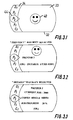
- the display is activated and takes the state as shown in Fig. 3.1, with an array or list of graphical icons representing image processing devices displayed in a scrollable format in section 34 and general information displayed in section 33, normally showing an icon indicating that all image processing devices are functioning properly in the form of a glyph, such as a happy blue smiley 70.
- a smiley with a less happy expression and a changed color (red) is displayed.
- T1 is the portable terminal 30 itself.
- a different graphical icon is assigned to each image processing device, the total system and the portable terminal itself.
- the icons may have the form of acronyms (such as shown in Fig. 3.1), but may also have a graphical appearance resembling the particular device, as is shown in Fig. 5.
- a static marker is provided on in the form of a selection loop 44, indicating the currently selected device.
- the array of icons is activated. Once activated, the array of icons can be scrolled by turning the rotary ring 35.
- the software controlling the user interface is programmed to scroll the array of icons in the same direction as the rotary ring 35.
- the software may also be programmed such that the movement of the array of icons is proportional to the movement of the rotary ring 35.
- the software is programmed such that the movement of the array of icons coincides with the movement of the rotary ring 35 in a manner that gives the operator the impression that the array of icons is mechanically connected to the rotary ring 35 because they move in unison.
- section 33 of the display 32 shows a happy smiley since the selected device is functioning properly. Below the smiley, the text "Printer 2" is displayed.
- selectable menu items "Status Details" and "Queued jobs" are displayed.
- One of the selectable items is highlighted, e.g. by using a different color for the selected item or by underlining.
- Turning the rotary ring 35 scrolls through the "list” of selectable menu items. The highlighted menu item is selected by pressing any of the "button" sections of the ring.
- Section 33 lists the details of the current job such as: “Machine”, “Status”, “Job Nr.”, “Client”, “Page”, and “Time remaining”.
- the selectable menu items “Next job” and "Previous job” are shown. Selecting "Next job” will display the details of the next job in the print queue, just as selecting “Previous job” will display the details of the job last finished. Again, pressing both "button” sections of the rotary ring 35 at the same time will bring the display in the status as shown in Fig. 3.2.
- the rotary ring 35 is provided with arresting positions in the form of "clicks", whereby each "click” corresponds to a next step in the scrolled array or list, i.e. one click selects the next graphical item in the loop 38.
- Errors such as paper jams, and other disturbances that need immediate attention are displayed with priority. Such events include paper jams, empty paper trays, low cooling liquid, full finishers, out of staples, toner empty, special insert needed, special paper needed, etc. These alerts are displayed immediately by showing a red and sad or even screaming smiley in display section 33, the specific expression being selected in dependence on the seriousness of the situation.
- Some alerts that do not require immediate attention such a low toner or low paper level in paper trays, are displayed in section 33 with a lower priority expression. These alerts are only displayed if the operator is in the vicinity of the image processing device in question, and with a green neutral smiley signaling that attention is needed, but not immediately. When the alert becomes more serious, the smiley expression may be changed into a more alarming one.
- a paper jam is a serious error requiring immediate operator action.
- the display turns to the state as shown in Fig. 3.7, and in accordance with operator selectable settings, also an audible and/or vibration alarm is issued.
- section 33 now shows a sad and red smiley. Below the smiley, the text “Error: Paper jam” in large red letters is displayed. There below the text “Printer 1" is displayed. At the bottom of section 33 the selectable menu items “OK”, “Details” and “Postpone” are displayed.
- the jammed printer 1 registers that the repair has been carried out it sends a signal to the portable terminal to turn to the status as in Fig. 3.1 with a happy smiley.
- the registration of the repair is part of the self check of the image processing device after all doors and covers are closed.
- Section 33 shows in the upper area the text "Printer 1". There below a detailed error message is shown, in the present example: "Error J14, paper jam top feeder”. In the lower part of section 33 the selectable menu items "Instructions" and "OK" are displayed.
- the selectable menu item "OK” is displayed, which when selected brings the display to the state as shown in Fig 3.11, in which the portable terminal returns to its initial setting before the paper jam occurred, that is, the state shown in Fig. 3.2 reporting the status of printer 2.
- it also shows a red unhappy smiley icon in the upper right hand corner of the display section 33 as a warning that one of the other devices has an error and the terminal is waiting for a signal that the repair has been carried out,
- Section 33 shows a scrollable list of selectable menu items comprising, in this example, "Alerts”, “Devices list”, “User interface”, “Colors”, “Postpone time”, “Language settings” and “Predetermined distance” (the last two items not shown). Scrolling the list with the rotary ring 35 highlights the selectable menu items one after another and pressing either the lower or upper button selects the highlighted menu item. The operation of carrying out changes to the settings is not shown here in detail and will be apparent to the skilled reader.
- FIG. 4 an alternative embodiment of the portable terminal 30 is shown.
- the display 32 has been adapted to display in section 34 a straight array with objects representing the image processing devices in section 34.
- Section 33 displays general information, operating status information and selectable menu items.
- the rotary ring 35 has been replaced by a slide switch 50.
- the slide switch 50 can be manipulated by the operator to slide upwards and downwards in the direction of the arrow 51.
- the slide switch 50 can be pressed in the direction of arrow 52 for selection purposes.
- the slide switch 50 is resiliently biased to take a neutral position in which it is in the middle of its translative range in the direction of arrow 51 and outwards at the end of its translative range in the direction of arrow 52.
- Section 33 of the display 32 is normally active, and sliding the slide switch 50 upwards results in the array of objects to scroll upwards and sliding the switch downwards results in the array to scroll downwards.
- Section 33 then becomes active, and shows the status information as described further above.
- the software can be programmed such that one upward movement of the slide switch 50 moves the array of objects upwards by one object so that the next object in the array is placed in the selection loop 44.
- the use of a display with in which graphical icons are used instead of acronyms is shown in Fig. 5.
- the movable array thus comprises different graphical icons.
- a particular graphical icon is assigned to each type of image processing device, e.g. printers are assigned the icon that is generally used for this purpose in PC software, a photocopiers are assigned a graphical icon resembling a photocopier, etc.
- the particular image processing device is further identified by a number displayed with the graphical icon.
- status icons may be combined with the device icons to give the operator a first indication of the status of all devices shown on the display. Examples of such status icons are a red cross for unavailable devices, an hour glass for devices temporarily out of service.
- a new image processing device When a new image processing device is added to the population of devices monitored with the aid of the portable terminal, its particulars are registered in the control program of the server 20 (Fig. 1) by a service engineer, or it may present itself to the server automatically.
- the server 20 then includes the new device in its status monitoring service and transmits installation data to the portable terminal 30, such that it may register the new device and add it to the list of devices in display section 34 and related monitoring service.
- an image processing device when removed from the population of devices, it is deleted from the monitoring service in the server 20. In that case, the server 20 sends a signal to the portable terminal 30 to delete the device from its display and service.
- the monitoring service is for the greater part implemented in the server 20 (Fig. 1), and the portable terminal simply operates as a user interface to the monitoring service in the server 20.
- Such an implementation has the advantage that data traffic between the server 20 and the portable terminal 30 is minimized.
- the server 20 It would also be possible to do without the server 20 and include a wireless transmitter into each of the devices.
- the devices would then themselves send their status data to the portable terminal, that would include a monitoring service for processing the status data of the devices.
- the control program of the portable terminal is also provided with a registering service to register all devices to be monitored.
Landscapes
- Engineering & Computer Science (AREA)
- Microelectronics & Electronic Packaging (AREA)
- Physics & Mathematics (AREA)
- General Physics & Mathematics (AREA)
- User Interface Of Digital Computer (AREA)
- Selective Calling Equipment (AREA)
Abstract
Description
The general term "image processing device" as used here includes printers, plotters, scanners, copiers, fax machines online finishers, off-line finishers and combinations or variations thereof, i.e. "image processing" includes also merely handling documents on sheets of paper.
The IC card can be inserted in an offline job commander for programming the IC card.
Events that concern normal, non-problematic, status changes such as starting or finishing printing, have no priority status and are only shown when the operator expressly selects the status of that device.
-
section 34 is used to display an arc-shaped array of objects representing individual image processing devices, preferably in the form of graphical icons, -
section 33 is used for displaying status and menu information.
In this way, the
By turning the
A static marker is provided on in the form of a
- Job Progress: 28%
- Finisher: 10%
- Paper Tray 1: 50%
- Paper Tray2: 100%
However, it would also be possible to implement the monitoring service in the portable terminal and use the
Claims (31)
- A method of monitoring operating status of a plurality of image processing devices located in a proximate environment, comprising
sending wireless signals incorporating operating status data for each of said image processing devices,
receiving said wireless signals in a portable terminal, and
presenting said status data to an operator of said portable terminal in the form of either a general system status indication or a device status indication regarding a particular image processing device, in accordance with a predetermined presentation scheme. - The method of claim 1, wherein
said predetermined presentation scheme prescribes presenting said general system status indication and automatically switching to said device status indication regarding a particular image processing device when a predetermined event occurs in that particular image processing device. - The method of claim 2, wherein
said predetermined presentation scheme is based on a predetermined priority scheme for events occurring in the devices. - The method of claim 3, wherein
said predetermined presentation scheme prescribes to always present a device status indication regarding a particular image processing device, when in that device an event having a high priority occurs. - The method of claim 3, wherein
said predetermined presentation scheme prescribes to conditionally present a device status indication regarding a particular image processing device, when in that device an event having a low priority occurs,
wherein "conditionally presenting" means that said device status indication is only presented when the portable terminal is within a predetermined distance from said particular image processing device. - The method of claim 4, wherein an event impeding operation of a device has a high priority.
- The method of claim 5, wherein an event hampering normal operation of a device, but not requiring immediate attention, has a low priority.
- The method of claim 1, including
enabling an operator to select either said general system status indication or said device status indication regarding a particular image processing device, using operating elements on said portable terminal. - The method of claim 1, wherein
said general system status and said device status information is presented on said portable terminal in one of at least two operator-selectable presentation levels, including a first, global, level and a second, detailed, level. - The method of claim 9, wherein
each of said presentation levels has an associated presentation format. - The method of claim 10, wherein
the presentation format associated with the first presentation level includes a simple graphical symbol. - The method of claim 4, wherein
said presenting a device status indication in connection with an event having a high priority includes an audible and/or vibrational alarm. - The method of claim 2, wherein
said portable terminal, when it presents a device status indication regarding a particular image processing device in connection with an event, prompts an operator for a response, selected from a set of possible response options, including at least an acknowledgement and a command to postpone that particular status presentation to a predetermined later time. - The method of claim 2, including
displaying, upon request of an operator through operating means on the portable terminal and in connection with an event in a device, service guidance information on said portable terminal. - A system for monitoring the operating status of a plurality of image processing devices located in a proximate environment, comprising
at least one transmitter connected to one or more of said plurality of image processing devices and being provided with means for sending wireless signals incorporating operating status data for said image processing devices and
a portable terminal provided with a receiver for receiving said wireless signals, with display means and with a presentation module for presenting on the display means said status data for each of said image processing devices in the form of either a general system status indication or a device status indication regarding a particular image processing device, in accordance with a predetermined presentation scheme. - A system according to claim 15, comprising
a server connected to said plurality of image processing devices for collecting said operating status data and passing said operating status data onto said at least one transmitter. - A system according to claim 15, in which
each of said image processing devices is provided with a transmitter for sending wireless signals incorporating image processing device status data and
said portable terminal is provided with means for collecting the status data of all of the image processing devices. - A system according to claim 15, in which each of said image processing devices and said portable terminal are connected to a wireless network.
- A system according to claim 15, in which said signals are RF or IR signals.
- A system according to claim 15, wherein
said predetermined presentation scheme prescribes presenting said general system status indication and automatically switching to said device status indication regarding a particular image processing device when a predetermined event occurs in that particular image processing device. - A system according to claim 20, wherein
said predetermined presentation scheme is based on a predetermined priority scheme for events occurring in the devices. - A system according to claim 21, wherein
said predetermined presentation scheme prescribes to always present a device status indication regarding a particular image processing device, when in that device an event having a high priority occurs. - A system according to claim 21, further including
a distance-sensing module for determining the distance between the portable terminal and at least one of the image processing devices,
wherein
said predetermined presentation scheme prescribes to conditionally present a device status indication regarding a particular image processing device, when in that device an event having a low priority occurs,
wherein "conditionally presenting" means that said device status indication is only presented when the portable terminal is within a predetermined distance from said particular image processing device. - A system according to claim 22, wherein an event impeding operation of a device has a high priority.
- A system according to claim 23, wherein an event hampering normal operation of a device, but not requiring immediate attention, has a low priority.
- A system according to claim 15, wherein
said portable terminal is provided with selection means for selecting either said general system status indication or a particular device status indication, and wherein
said presentation module is connected to said selection means for presenting on the display of the portable terminal the selected status indication. - A system according to claim 26, said selection means of the portable terminal including:said array being movable along said marker or vice versa,a movable operating element,a selection display module for at least partially displaying an array of display objects representing the total system and the individual devices and for displaying a marker, on the display of the terminal,
wherein
the movement of said array or marker is substantially coinciding with the movement of said movable operating element and
said movable operating element is so located that it perceptually at least partially overlaps with the display such that said array or said marker appears to be part of the operating element. - A system according to claim 27, wherein said movable operating element is a rotary ring and said array is circular or at least arc shaped.
- A system according to claim 15, wherein
said presentation module is adapted to display status information on the display of said portable terminal in one of at least two operator-selectable presentation levels, including a first, global, level and a second, detailed, level, each of said presentation levels having an associated presentation format. - A system according to claim 15, wherein the portable terminal is provided with means for generating an audible and/or vibrational alarm.
- A portable terminal according to any one of claims 15 to 30.
Priority Applications (1)
| Application Number | Priority Date | Filing Date | Title |
|---|---|---|---|
| EP03078046.4A EP1426833B1 (en) | 2002-10-14 | 2003-09-30 | Status monitoring of a plurality of image processing devices |
Applications Claiming Priority (3)
| Application Number | Priority Date | Filing Date | Title |
|---|---|---|---|
| EP02079457 | 2002-10-14 | ||
| EP02079457 | 2002-10-14 | ||
| EP03078046.4A EP1426833B1 (en) | 2002-10-14 | 2003-09-30 | Status monitoring of a plurality of image processing devices |
Publications (3)
| Publication Number | Publication Date |
|---|---|
| EP1426833A2 true EP1426833A2 (en) | 2004-06-09 |
| EP1426833A3 EP1426833A3 (en) | 2006-07-26 |
| EP1426833B1 EP1426833B1 (en) | 2014-11-12 |
Family
ID=32313837
Family Applications (1)
| Application Number | Title | Priority Date | Filing Date |
|---|---|---|---|
| EP03078046.4A Expired - Lifetime EP1426833B1 (en) | 2002-10-14 | 2003-09-30 | Status monitoring of a plurality of image processing devices |
Country Status (1)
| Country | Link |
|---|---|
| EP (1) | EP1426833B1 (en) |
Cited By (1)
| Publication number | Priority date | Publication date | Assignee | Title |
|---|---|---|---|---|
| WO2013113697A1 (en) | 2012-01-31 | 2013-08-08 | Oce-Technologies B.V. | Method for managing a plurality of image processing devices, computer-program product, fleet management system, mobile device, and monitoring device therefor |
Family Cites Families (6)
| Publication number | Priority date | Publication date | Assignee | Title |
|---|---|---|---|---|
| US5398257A (en) * | 1993-01-11 | 1995-03-14 | Groenteman; Frank S. | Copier and monitoring network |
| US5414494A (en) * | 1993-12-06 | 1995-05-09 | Xerox Corporation | Automatic call to selected remote operators in response to predetermined machine conditions |
| US5822221A (en) * | 1996-12-04 | 1998-10-13 | Groenteman; Frank S. | Office machine monitoring device |
| US6665425B1 (en) * | 1999-12-16 | 2003-12-16 | Xerox Corporation | Systems and methods for automated image quality based diagnostics and remediation of document processing systems |
| JP2002262369A (en) * | 2001-02-27 | 2002-09-13 | Canon Inc | Data radio communication system and method for displaying operation status of peripheral device |
| US7355730B2 (en) * | 2001-03-21 | 2008-04-08 | Toshiba Tec Germany Imaging Systems Gmbh | Office machine that can be remote-maintenanced via a computer network and a management or/and support or/and report or/and information system comprising a plurality of office machines |
-
2003
- 2003-09-30 EP EP03078046.4A patent/EP1426833B1/en not_active Expired - Lifetime
Cited By (1)
| Publication number | Priority date | Publication date | Assignee | Title |
|---|---|---|---|---|
| WO2013113697A1 (en) | 2012-01-31 | 2013-08-08 | Oce-Technologies B.V. | Method for managing a plurality of image processing devices, computer-program product, fleet management system, mobile device, and monitoring device therefor |
Also Published As
| Publication number | Publication date |
|---|---|
| EP1426833A3 (en) | 2006-07-26 |
| EP1426833B1 (en) | 2014-11-12 |
Similar Documents
| Publication | Publication Date | Title |
|---|---|---|
| US7146293B2 (en) | Status monitoring of a plurality of image processing devices | |
| US7536653B2 (en) | Selection mechanism in a portable terminal | |
| US7792927B2 (en) | Output requesting apparatus via a network for user-position and apparatus-position information | |
| JP4251198B2 (en) | Printing control method and printing control apparatus | |
| JP2003308195A (en) | Information providing method and information providing system | |
| US10848639B2 (en) | Image forming apparatus, image forming system, and error notification method | |
| US20200236197A1 (en) | Beacon utilization system, method, beacon utilization method | |
| EP1115082A2 (en) | Portable barcode printer with control and display for function keys | |
| EP1164469A1 (en) | Remote control of interactive printing | |
| JP2005018607A (en) | Remote control device and remote control system | |
| EP1426833B1 (en) | Status monitoring of a plurality of image processing devices | |
| JP2017062595A (en) | Mobile terminal and program | |
| EP1411418A2 (en) | Selection mechanism in a portable terminal | |
| EP3792069A1 (en) | Appliance management system | |
| JP2006004160A (en) | Mobile printer system and control method of mobile printer system | |
| EP3543836A1 (en) | Operation apparatus, image forming apparatus and method of displaying screen | |
| US20040158632A1 (en) | Recovery of interrupted communication for remote management of devices | |
| US7532346B2 (en) | Information collecting apparatus, rebooting method, program, and remote maintenance system | |
| JP4133579B2 (en) | Image processing device management system | |
| JP2005165467A (en) | Information processing apparatus and method, and program | |
| US20210400151A1 (en) | Information processing apparatus, portable communication terminal, and non-transitory computer-readable data recording medium having program for controlling information processing apparatus or portable communication terminal recorded thereon | |
| US9258443B2 (en) | Image forming apparatus remotely operated by external terminal, image forming system including the same, and recording medium | |
| US20040153688A1 (en) | Abnormality management device for an image forming device, abnormality management system, and program for the same | |
| JP2008160296A (en) | Image forming apparatus, and setting information display program thereof | |
| JP2018107781A (en) | Image processing apparatus, method for controlling image processing apparatus, system, and program |
Legal Events
| Date | Code | Title | Description |
|---|---|---|---|
| PUAI | Public reference made under article 153(3) epc to a published international application that has entered the european phase |
Free format text: ORIGINAL CODE: 0009012 |
|
| AK | Designated contracting states |
Kind code of ref document: A2 Designated state(s): AT BE BG CH CY CZ DE DK EE ES FI FR GB GR HU IE IT LI LU MC NL PT RO SE SI SK TR |
|
| AX | Request for extension of the european patent |
Extension state: AL LT LV MK |
|
| PUAL | Search report despatched |
Free format text: ORIGINAL CODE: 0009013 |
|
| AK | Designated contracting states |
Kind code of ref document: A3 Designated state(s): AT BE BG CH CY CZ DE DK EE ES FI FR GB GR HU IE IT LI LU MC NL PT RO SE SI SK TR |
|
| AX | Request for extension of the european patent |
Extension state: AL LT LV MK |
|
| 17P | Request for examination filed |
Effective date: 20070126 |
|
| AKX | Designation fees paid |
Designated state(s): AT BE BG CH CY CZ DE DK EE ES FI FR GB GR HU IE IT LI LU MC NL PT RO SE SI SK TR |
|
| 17Q | First examination report despatched |
Effective date: 20071113 |
|
| GRAP | Despatch of communication of intention to grant a patent |
Free format text: ORIGINAL CODE: EPIDOSNIGR1 |
|
| INTG | Intention to grant announced |
Effective date: 20140523 |
|
| GRAS | Grant fee paid |
Free format text: ORIGINAL CODE: EPIDOSNIGR3 |
|
| GRAA | (expected) grant |
Free format text: ORIGINAL CODE: 0009210 |
|
| AK | Designated contracting states |
Kind code of ref document: B1 Designated state(s): AT BE BG CH CY CZ DE DK EE ES FI FR GB GR HU IE IT LI LU MC NL PT RO SE SI SK TR |
|
| REG | Reference to a national code |
Ref country code: GB Ref legal event code: FG4D |
|
| REG | Reference to a national code |
Ref country code: CH Ref legal event code: EP |
|
| REG | Reference to a national code |
Ref country code: AT Ref legal event code: REF Ref document number: 696097 Country of ref document: AT Kind code of ref document: T Effective date: 20141115 |
|
| REG | Reference to a national code |
Ref country code: IE Ref legal event code: FG4D |
|
| REG | Reference to a national code |
Ref country code: DE Ref legal event code: R096 Ref document number: 60346976 Country of ref document: DE Effective date: 20141224 |
|
| REG | Reference to a national code |
Ref country code: NL Ref legal event code: T3 |
|
| REG | Reference to a national code |
Ref country code: AT Ref legal event code: MK05 Ref document number: 696097 Country of ref document: AT Kind code of ref document: T Effective date: 20141112 |
|
| PG25 | Lapsed in a contracting state [announced via postgrant information from national office to epo] |
Ref country code: PT Free format text: LAPSE BECAUSE OF FAILURE TO SUBMIT A TRANSLATION OF THE DESCRIPTION OR TO PAY THE FEE WITHIN THE PRESCRIBED TIME-LIMIT Effective date: 20150312 Ref country code: ES Free format text: LAPSE BECAUSE OF FAILURE TO SUBMIT A TRANSLATION OF THE DESCRIPTION OR TO PAY THE FEE WITHIN THE PRESCRIBED TIME-LIMIT Effective date: 20141112 Ref country code: FI Free format text: LAPSE BECAUSE OF FAILURE TO SUBMIT A TRANSLATION OF THE DESCRIPTION OR TO PAY THE FEE WITHIN THE PRESCRIBED TIME-LIMIT Effective date: 20141112 |
|
| PG25 | Lapsed in a contracting state [announced via postgrant information from national office to epo] |
Ref country code: GR Free format text: LAPSE BECAUSE OF FAILURE TO SUBMIT A TRANSLATION OF THE DESCRIPTION OR TO PAY THE FEE WITHIN THE PRESCRIBED TIME-LIMIT Effective date: 20150213 Ref country code: CY Free format text: LAPSE BECAUSE OF FAILURE TO SUBMIT A TRANSLATION OF THE DESCRIPTION OR TO PAY THE FEE WITHIN THE PRESCRIBED TIME-LIMIT Effective date: 20141112 Ref country code: AT Free format text: LAPSE BECAUSE OF FAILURE TO SUBMIT A TRANSLATION OF THE DESCRIPTION OR TO PAY THE FEE WITHIN THE PRESCRIBED TIME-LIMIT Effective date: 20141112 Ref country code: SE Free format text: LAPSE BECAUSE OF FAILURE TO SUBMIT A TRANSLATION OF THE DESCRIPTION OR TO PAY THE FEE WITHIN THE PRESCRIBED TIME-LIMIT Effective date: 20141112 |
|
| PG25 | Lapsed in a contracting state [announced via postgrant information from national office to epo] |
Ref country code: SK Free format text: LAPSE BECAUSE OF FAILURE TO SUBMIT A TRANSLATION OF THE DESCRIPTION OR TO PAY THE FEE WITHIN THE PRESCRIBED TIME-LIMIT Effective date: 20141112 Ref country code: DK Free format text: LAPSE BECAUSE OF FAILURE TO SUBMIT A TRANSLATION OF THE DESCRIPTION OR TO PAY THE FEE WITHIN THE PRESCRIBED TIME-LIMIT Effective date: 20141112 Ref country code: CZ Free format text: LAPSE BECAUSE OF FAILURE TO SUBMIT A TRANSLATION OF THE DESCRIPTION OR TO PAY THE FEE WITHIN THE PRESCRIBED TIME-LIMIT Effective date: 20141112 Ref country code: RO Free format text: LAPSE BECAUSE OF FAILURE TO SUBMIT A TRANSLATION OF THE DESCRIPTION OR TO PAY THE FEE WITHIN THE PRESCRIBED TIME-LIMIT Effective date: 20141112 Ref country code: EE Free format text: LAPSE BECAUSE OF FAILURE TO SUBMIT A TRANSLATION OF THE DESCRIPTION OR TO PAY THE FEE WITHIN THE PRESCRIBED TIME-LIMIT Effective date: 20141112 |
|
| REG | Reference to a national code |
Ref country code: DE Ref legal event code: R097 Ref document number: 60346976 Country of ref document: DE |
|
| PLBE | No opposition filed within time limit |
Free format text: ORIGINAL CODE: 0009261 |
|
| STAA | Information on the status of an ep patent application or granted ep patent |
Free format text: STATUS: NO OPPOSITION FILED WITHIN TIME LIMIT |
|
| 26N | No opposition filed |
Effective date: 20150813 |
|
| PG25 | Lapsed in a contracting state [announced via postgrant information from national office to epo] |
Ref country code: IT Free format text: LAPSE BECAUSE OF FAILURE TO SUBMIT A TRANSLATION OF THE DESCRIPTION OR TO PAY THE FEE WITHIN THE PRESCRIBED TIME-LIMIT Effective date: 20141112 |
|
| PG25 | Lapsed in a contracting state [announced via postgrant information from national office to epo] |
Ref country code: SI Free format text: LAPSE BECAUSE OF FAILURE TO SUBMIT A TRANSLATION OF THE DESCRIPTION OR TO PAY THE FEE WITHIN THE PRESCRIBED TIME-LIMIT Effective date: 20141112 |
|
| PG25 | Lapsed in a contracting state [announced via postgrant information from national office to epo] |
Ref country code: MC Free format text: LAPSE BECAUSE OF FAILURE TO SUBMIT A TRANSLATION OF THE DESCRIPTION OR TO PAY THE FEE WITHIN THE PRESCRIBED TIME-LIMIT Effective date: 20141112 Ref country code: LU Free format text: LAPSE BECAUSE OF FAILURE TO SUBMIT A TRANSLATION OF THE DESCRIPTION OR TO PAY THE FEE WITHIN THE PRESCRIBED TIME-LIMIT Effective date: 20150930 |
|
| REG | Reference to a national code |
Ref country code: CH Ref legal event code: PL |
|
| REG | Reference to a national code |
Ref country code: IE Ref legal event code: MM4A |
|
| PG25 | Lapsed in a contracting state [announced via postgrant information from national office to epo] |
Ref country code: LI Free format text: LAPSE BECAUSE OF NON-PAYMENT OF DUE FEES Effective date: 20150930 Ref country code: CH Free format text: LAPSE BECAUSE OF NON-PAYMENT OF DUE FEES Effective date: 20150930 Ref country code: IE Free format text: LAPSE BECAUSE OF NON-PAYMENT OF DUE FEES Effective date: 20150930 |
|
| REG | Reference to a national code |
Ref country code: FR Ref legal event code: PLFP Year of fee payment: 14 |
|
| PG25 | Lapsed in a contracting state [announced via postgrant information from national office to epo] |
Ref country code: BG Free format text: LAPSE BECAUSE OF FAILURE TO SUBMIT A TRANSLATION OF THE DESCRIPTION OR TO PAY THE FEE WITHIN THE PRESCRIBED TIME-LIMIT Effective date: 20141112 Ref country code: HU Free format text: LAPSE BECAUSE OF FAILURE TO SUBMIT A TRANSLATION OF THE DESCRIPTION OR TO PAY THE FEE WITHIN THE PRESCRIBED TIME-LIMIT; INVALID AB INITIO Effective date: 20030930 |
|
| PG25 | Lapsed in a contracting state [announced via postgrant information from national office to epo] |
Ref country code: TR Free format text: LAPSE BECAUSE OF FAILURE TO SUBMIT A TRANSLATION OF THE DESCRIPTION OR TO PAY THE FEE WITHIN THE PRESCRIBED TIME-LIMIT Effective date: 20141112 |
|
| REG | Reference to a national code |
Ref country code: FR Ref legal event code: PLFP Year of fee payment: 15 |
|
| PG25 | Lapsed in a contracting state [announced via postgrant information from national office to epo] |
Ref country code: BE Free format text: LAPSE BECAUSE OF FAILURE TO SUBMIT A TRANSLATION OF THE DESCRIPTION OR TO PAY THE FEE WITHIN THE PRESCRIBED TIME-LIMIT Effective date: 20141112 |
|
| PGFP | Annual fee paid to national office [announced via postgrant information from national office to epo] |
Ref country code: FR Payment date: 20170928 Year of fee payment: 15 Ref country code: GB Payment date: 20170921 Year of fee payment: 15 Ref country code: DE Payment date: 20170928 Year of fee payment: 15 |
|
| PGFP | Annual fee paid to national office [announced via postgrant information from national office to epo] |
Ref country code: NL Payment date: 20170928 Year of fee payment: 15 |
|
| REG | Reference to a national code |
Ref country code: DE Ref legal event code: R119 Ref document number: 60346976 Country of ref document: DE |
|
| REG | Reference to a national code |
Ref country code: NL Ref legal event code: MM Effective date: 20181001 |
|
| GBPC | Gb: european patent ceased through non-payment of renewal fee |
Effective date: 20180930 |
|
| PG25 | Lapsed in a contracting state [announced via postgrant information from national office to epo] |
Ref country code: NL Free format text: LAPSE BECAUSE OF NON-PAYMENT OF DUE FEES Effective date: 20181001 |
|
| PG25 | Lapsed in a contracting state [announced via postgrant information from national office to epo] |
Ref country code: DE Free format text: LAPSE BECAUSE OF NON-PAYMENT OF DUE FEES Effective date: 20190402 |
|
| PG25 | Lapsed in a contracting state [announced via postgrant information from national office to epo] |
Ref country code: FR Free format text: LAPSE BECAUSE OF NON-PAYMENT OF DUE FEES Effective date: 20180930 |
|
| PG25 | Lapsed in a contracting state [announced via postgrant information from national office to epo] |
Ref country code: GB Free format text: LAPSE BECAUSE OF NON-PAYMENT OF DUE FEES Effective date: 20180930 |