EP1426797A1 - Variable optical attenuator - Google Patents
Variable optical attenuator Download PDFInfo
- Publication number
- EP1426797A1 EP1426797A1 EP03027332A EP03027332A EP1426797A1 EP 1426797 A1 EP1426797 A1 EP 1426797A1 EP 03027332 A EP03027332 A EP 03027332A EP 03027332 A EP03027332 A EP 03027332A EP 1426797 A1 EP1426797 A1 EP 1426797A1
- Authority
- EP
- European Patent Office
- Prior art keywords
- coil
- mirror
- variable optical
- plate
- optical attenuator
- Prior art date
- Legal status (The legal status is an assumption and is not a legal conclusion. Google has not performed a legal analysis and makes no representation as to the accuracy of the status listed.)
- Withdrawn
Links
- 230000003287 optical effect Effects 0.000 title claims abstract description 48
- 239000000835 fiber Substances 0.000 claims abstract description 25
- 230000004907 flux Effects 0.000 claims abstract description 8
- 230000001902 propagating effect Effects 0.000 claims abstract 4
- 239000002184 metal Substances 0.000 claims description 43
- 229910052751 metal Inorganic materials 0.000 claims description 43
- 238000003466 welding Methods 0.000 claims description 9
- 239000000463 material Substances 0.000 claims description 7
- 239000010410 layer Substances 0.000 description 9
- 238000009413 insulation Methods 0.000 description 7
- 238000000034 method Methods 0.000 description 7
- 238000004519 manufacturing process Methods 0.000 description 6
- 229910000906 Bronze Inorganic materials 0.000 description 5
- OAICVXFJPJFONN-UHFFFAOYSA-N Phosphorus Chemical compound [P] OAICVXFJPJFONN-UHFFFAOYSA-N 0.000 description 5
- 239000010974 bronze Substances 0.000 description 5
- KUNSUQLRTQLHQQ-UHFFFAOYSA-N copper tin Chemical compound [Cu].[Sn] KUNSUQLRTQLHQQ-UHFFFAOYSA-N 0.000 description 5
- 230000008569 process Effects 0.000 description 5
- 239000000853 adhesive Substances 0.000 description 4
- 230000008859 change Effects 0.000 description 4
- 238000005530 etching Methods 0.000 description 3
- PCHJSUWPFVWCPO-UHFFFAOYSA-N gold Chemical compound [Au] PCHJSUWPFVWCPO-UHFFFAOYSA-N 0.000 description 3
- 239000010931 gold Substances 0.000 description 3
- 229910052737 gold Inorganic materials 0.000 description 3
- 230000000644 propagated effect Effects 0.000 description 3
- 238000004544 sputter deposition Methods 0.000 description 3
- 239000012790 adhesive layer Substances 0.000 description 2
- 239000011247 coating layer Substances 0.000 description 2
- 239000004020 conductor Substances 0.000 description 2
- 239000013078 crystal Substances 0.000 description 2
- 239000002223 garnet Substances 0.000 description 2
- 238000001459 lithography Methods 0.000 description 2
- 239000011347 resin Substances 0.000 description 2
- 229920005989 resin Polymers 0.000 description 2
- 230000004044 response Effects 0.000 description 2
- XUIMIQQOPSSXEZ-UHFFFAOYSA-N Silicon Chemical compound [Si] XUIMIQQOPSSXEZ-UHFFFAOYSA-N 0.000 description 1
- 230000001070 adhesive effect Effects 0.000 description 1
- 238000005520 cutting process Methods 0.000 description 1
- 230000001419 dependent effect Effects 0.000 description 1
- 238000011161 development Methods 0.000 description 1
- 230000018109 developmental process Effects 0.000 description 1
- 239000012212 insulator Substances 0.000 description 1
- 238000005259 measurement Methods 0.000 description 1
- 239000007769 metal material Substances 0.000 description 1
- 239000013307 optical fiber Substances 0.000 description 1
- 238000003825 pressing Methods 0.000 description 1
- 229910052761 rare earth metal Inorganic materials 0.000 description 1
- 150000002910 rare earth metals Chemical class 0.000 description 1
- 239000004065 semiconductor Substances 0.000 description 1
- 229910052710 silicon Inorganic materials 0.000 description 1
- 239000010703 silicon Substances 0.000 description 1
- 238000005476 soldering Methods 0.000 description 1
- 238000004804 winding Methods 0.000 description 1
Images




Classifications
-
- G—PHYSICS
- G02—OPTICS
- G02B—OPTICAL ELEMENTS, SYSTEMS OR APPARATUS
- G02B26/00—Optical devices or arrangements for the control of light using movable or deformable optical elements
- G02B26/02—Optical devices or arrangements for the control of light using movable or deformable optical elements for controlling the intensity of light
-
- G—PHYSICS
- G02—OPTICS
- G02B—OPTICAL ELEMENTS, SYSTEMS OR APPARATUS
- G02B6/00—Light guides; Structural details of arrangements comprising light guides and other optical elements, e.g. couplings
- G02B6/24—Coupling light guides
- G02B6/26—Optical coupling means
- G02B6/264—Optical coupling means with optical elements between opposed fibre ends which perform a function other than beam splitting
- G02B6/266—Optical coupling means with optical elements between opposed fibre ends which perform a function other than beam splitting the optical element being an attenuator
Definitions
- This invention relates to an optical device for variable attenuation of the intensity of light input thereto.
- variable optical attenuator comprises a Faraday rotator placed between two polarizers.
- the optical attenuator of this type is disclosed in JP-B H04-2934.
- garnet crystal is used as the Faraday rotator.
- garnet crystal has a property of large wavelength dependence so that the optical attenuator also has the large wavelength dependence of light intensity attenuation function.
- variable optical attenuator disclosed in JP-A 2000-131626 solves the above-mentioned wavelength dependence problem.
- the variable optical attenuator of JP-A 2000-131626 comprises incoming and outgoing fibers, a mirror, and a micromachine on which the mirror is movably disposed.
- a light beam propagated through the incoming fiber is reflected by the mirror.
- at least one part of the reflected light beam is propagated into the outgoing fiber.
- the intensity of the light beam within the outgoing fiber depends on the angle of reflection at the mirror, wherein the angle can be adjusted by the rotation of the mirror by means of the micromachine.
- the micromachine is a silicon micromachine and works in accordance with an electrostatic principle.
- the attenuator of JP-A 2000-131626 has some problems. One problem is that it is difficult to produce them at low cost. Another problem is that the attenuation amount of light intensity cannot be adjusted in linearly response to the change of the driving power supplied to the micromachine because of its electrostatic operation principle. This means that it is difficult to adjust the attenuation amount.
- variable optical attenuator 100 comprises incoming and outgoing fibers 10, 20, a single ferrule 30, a mirror 40, a lens 50 and an actuator 60.
- the incoming and the outgoing fibers 10, 20 have end portions 11, 21 and the portions 12, 22 near thereto.
- the end portions 11, 21 and the portions 12, 22 near thereto of the incoming and the outgoing fibers 10, 20 are fixedly arranged in the ferrule 30 so as to be parallel to each other.
- the mirror 40 is supported by the actuator 60 so that it is able to rotate as described afterwards.
- the lens 50 is held by a lens holder 51, which is formed as a part of the actuator 60, and is placed between the end portions 11, 21 of the incoming and the outgoing fibers 10, 20 and the mirror 40.
- the ferrule 30 is fixed to the lens holder 51 so that the incoming and the outgoing fibers 10, 20 are fixed to the part of the actuator 60.
- the end portions 11, 21 of the incoming and the outgoing fibers 10, 20 face the lens 50.
- An incoming light beam propagated through the incoming fiber 10 is directed to the mirror 40 through the lens 50.
- the light beam is reflected by the mirror 40.
- a part of the reflected light beam is introduced into the outgoing fiber 20 through the lens 50.
- the light intensity of the light beam within the outgoing fiber 20 is determined by the angle of reflection at the mirror 40.
- the angle of reflection at the mirror 40 is adjusted by means of the actuator 60, which utilizes a Lorentz force.
- the mirror 40 is manufactured by sputtering gold against a surface of a base material which is made of an insulator.
- the base material of the mirror 40 may be made of a semiconductor material or a conductive material.
- the actuator 60 comprises a metal plate 61, two hinge springs 62, a housing 63, a coil 64, two permanent magnets 65 and two terminals 66.
- the metal plate 61 is formed integral with the hinge springs 62, as shown in Fig. 2.
- the housing 63 serves as a base member, on which the other components of the actuator 60 are arranged.
- One part of the housing 63 constitutes the lens holder 51 as mentioned above with reference to Fig. 1.
- the housing 63 is formed with a concave portion 63a, which is shown in Figs. 3 and 4.
- the metal plate 61 is suspended from the housing 63 by means of the hinge springs 62 so that the metal plate 61 is able to rotate within the concave portion with no contact with the housing 63, as best shown in Fig. 3. As far as the metal plate 61 can rotate, it can be held or supported by the housing 63 by the use of any other means.
- the rotation axis 61a of the metal plate 61 extends in a Y-direction.
- the mirror 40 is disposed and fixed on a surface of the metal plate 61.
- the position of the mirror 40 is a center of the metal plate 61 in this embodiment so that the mirror 40 is arranged on the rotation axis 61a of the metal plate 61.
- the metal plate 61 is generally perpendicular to a Z-direction, which is perpendicular to the Y-direction, so that the mirror 40 is also generally perpendicular to the Z-direction under the initial state.
- the Z-direction is also a direction along which the incoming light beam is launched on the mirror 40 from the incoming fiber 10.
- the hinge springs 62 are positioned at the opposite ends of the metal plate 61 in the Y-direction.
- Each of the hinge springs 62 has a symmetrical shape with respect to the rotation axis 61a so that a linear movement can be ensured upon the rotation of the metal plate 61.
- the coil 64 is disposed and fixed on the metal plate 61, especially, on the same surface as the mirror 40 disposed.
- the coil 64 is an air-core coil, which has a center on the rotation axis 61 a of the metal plate 61.
- the coil 64 surrounds the mirror 40 in a plane parallel to the metal plate 61.
- the coil 64 is formed by winding a coil line, which has an adhesive layer as its outermost layer so that the coil line has a self-welding function.
- the coil line further has an insulation coating layer as its layer inner-next to the outermost layer, so that the neighboring line portions are prevented from being short-circuited electrically when the wound coil 64 is formed.
- the insulation coating layer provides a desirable insulation function even if its thickness is several ⁇ m.
- the coil 64 can provide a large Lorentz force for its size when a driving current is supplied to the coil 64 as mentioned afterwards.
- the coil 64 may be wound in the form of one turn or several turns and may be arranged on a surface opposite to the surface where the mirror 40 is arranged.
- the coil 64 may be formed by using a bobbin or a similar tool which can keep the wound form of the coil 64.
- the coil 64 and the mirror 40 rotate together with the metal plate 61 when the metal plate 61 rotates, and vice versa.
- the coil 64 rotates in accordance with the Lorentz force, and the metal plate 61 and the mirror 40 rotate accordingly.
- the coil 64 is supplied with the driving current.
- the terminals 66 are provided for the housing 63, being insulated from each other.
- the terminals 66 are electrically connected to the respective ends 64a, 64b of the coil 64.
- the terminal is arranged in the Y-direction, i.e. a direction along the rotation axis 61 a.
- the permanent magnets 65 are fixed to the housing 63.
- a ferritic permanent magnet or a rare earth permanent magnet can be used as the permanent magnet 65.
- the permanent magnets 65 are arranged so that the coil 64 is placed between the permanent magnets 65 in an X-direction perpendicular to the Y and the Z-directions.
- the permanent magnets 65 generate predetermined magnetic flux density B, which has a vector along the X-direction in this embodiment. In other words, the predetermined magnetic flux density B is perpendicular to the rotation axis 61a.
- variable optical attenuator 100 of the first embodiment can provide an easy operation on the adjustment of the angle of reflection at the mirror 40 and on the adjustment of the light intensity attenuation amount, accordingly.
- the metal plate 61 is formed in a predetermined shape by pressing and etching a flexible metal material, which can provide a spring force.
- the metal plate 61 is made of phosphor bronze.
- the above-mentioned self-welding coil line is wound around a coil winder or an arbor which has a shape of the air-core area of the coil 64.
- the wound coil line is supplied with warm air so that the self-welding function makes and fixes the form of the coil 64.
- the mirror 40 is formed by sputtering gold on the base material. At that time, Ti, Cr, Ta or the like is used as an adhesive seed layer. After the sputtering process, a cutting process is carried out so that the mirror 40 of a predetermined shape can be obtained.
- the coil 64 is fixed on the metal plate 61 by the use of an adhesive agent or by welding.
- the mirror 40 is fixed on the metal plate 61 by the use of an adhesive agent or by welding.
- the hinge springs 62 are connected to the housing 63 by the use of an adhesive agent or by welding so that the metal plate 61 is held by the housing 63.
- the permanent magnets 65 are fixed to the housing 63 by the use of an adhesive layer or welding.
- the manufacturing of the actuator 60 with the mirror 40 is made of the respective fabrication processes of the components and the simple assembly process thereof. Therefore, the actuator 60 of the present embodiment can be manufactured easily so that the variable optical attenuator 100 of the present embodiment is suitable for mass-production.
- variable optical attenuator To verify optical properties of the variable optical attenuator according to the first embodiment, some samples were manufactured, and their properties were measured.
- the length of the metal plate 61 is 6-9 mm, the width thereof is 5-7 mm, and the thickness thereof is 0.04-0.1mm.
- the length of the hinge spring 62 is 0.8-2.0 mm, and the width thereof is 0.1-0.25 mm.
- the length of the air-core area of the coil 64 is 1.5-2.5 mm, and the width thereof is 0.5-1.0 mm.
- the length of the external form of the coil 64 is 4-5 mm, and the width thereof is 3-5 mm.
- the length of the mirror 40 is 0.7-1 mm, and the width thereof is 0.7-1 mm.
- the thickness of the base material of the mirror 40 is 0.05-0.3 mm, and the thickness of the gold layer formed on the base material is 0.02-0.05 mm.
- each of the permanent magnets is 6-10 mm, the width thereof is 0.5-2 mm, and the thickness thereof is 0.5-2 mm.
- the total of the diameters of the first and the second optical fibers is 1.0-2.0 mm, and the length thereof is 5-10 mm.
- the length of the lens is 3.0-4.5 mm, and the outer diameter thereof is 3.0-4.5 mm.
- the length of the variable optical attenuator 100 is 18-20 mm, the width thereof is 13-17 mm, and the height thereof is 8-12 mm.
- the measurements were carried out on the samples' optical properties.
- the driving current of the coil 64 was 10 mA
- the optical loss was 4.3dB.
- the driving current was 20 mA
- the optical loss was 14.0 dB.
- driving current was 30 mA
- the optical loss was 25.6 dB.
- the driving current was 35 mA
- the optical loss was 31.9 dB.
- the attenuation amount at the variable optical attenuator responded linearly to the change of the driving current supplied for the coil 64.
- variable optical attenuator according to a second embodiment of the present invention is similar to the first embodiment expect for the electrical connections between the ends 64a, 64b of the coil 64 and the terminals 66.
- ends 64a, 64b are directly connected to the terminals 66.
- two intermediate electrodes 67 are provided on the metal plate 5, as shown in Figs. 5 and 6.
- the intermediate electrodes 67 are electrically insulated from each other, while electrically connected to the ends 64a, 64b by soldering or by welding.
- the intermediate electrodes 67 are also electrically connected to the terminals 66 by using conductive patterns 68 which are formed on the metal plate 61 via an insulation layer 69.
- the ends 64a, 64b are fixed to and connected to the metal plate 61 so that almost all the mechanical stress, which might occur at the ends 64a, 64b upon the operation of the actuator 60 in the first embodiment, can be solved. Therefore, the connection reliability of the ends 64a, 64b of the coil 64 to the terminals 66 increases.
- the actuator 60 according to the second embodiment can be manufactured as described below.
- the manufacturing method of the actuator 60 is almost the same as the first embodiment, but differs from the first embodiment in that the metal plate 61 is formed by the use of lithography technique and etching process.
- the metal plate 61 is made of phosphor bronze. On one surface of the phosphor bronze plate, the insulation layer 69 is formed. For example, the insulation layer 69 is made of photosensitive resin. On the other surface of the phosphor bronze plate, a protection film is formed. The lithography process is carried out on the photosensitive resin so that the external form of the metal plate 61 and the hinge springs 62 is formed. By using a metal mask which has a negative shape of the intermediate electrodes 67 and the conductive patterns 68, conductive materials are sputtered on the insulation layer 69. After that, the metal plate 61 is formed by etching with a predetermined etchant against phosphor bronze. Then, the protection film is removed by the use of a predetermined etchant for the protection film. The metal plate 61 is fitted to the housing 63 while the conductive patterns 68 are electrically connected to the terminals 66.
- variable optical attenuator device 200 is comprised of a plurality of variable optical attenuators 100, each of which is explained in the first or the second embodiment. In other words, a plurality of attenuation functions are integrated into the variable optical attenuator device 200 of the present embodiment.
- a plurality of metal plates 61 are arranged on a single housing 63.
- the mirror 40 and the coil 64 are arranged as described in the first or the second embodiment.
- Each of the permanent magnets 65 1 , 65 2 , 65 3 , 65 4 is used in common to the variable optical attenuators 100.
- only one set of permanent magnets 65 may be used.
- all of the metal plates 61 each mounting the mirror 40 and the coil 64 are placed between the set of permanent magnets 65.
- TEC Thermally-diffused Expanded Core fibers
- the lens 50 can be omitted.
- two coils 64 may be provided on the both surfaces of the metal plate 61. In the case of two coils 64, a larger Lorentz force can be obtained.
- the coil 64 may be disposed on a surface of the metal plate 61, which is opposite to the other surface where the mirror 40 is fixed. This arrangement of the coil 64 and the mirror 40 on different surfaces of the metal plate 61 can provide flexibility on design.
Landscapes
- Physics & Mathematics (AREA)
- General Physics & Mathematics (AREA)
- Optics & Photonics (AREA)
- Mechanical Light Control Or Optical Switches (AREA)
- Micromachines (AREA)
Abstract
A variable optical attenuator comprises an incoming fiber for
propagating an incoming light beam, a mirror (40) for reflecting the
incoming light beam as a reflected light beam and an outgoing fiber for
propagating as an outgoing light beam at least one part of the reflected light
beam. The light intensity of the outgoing light beam is determined by the
angle of reflection at the mirror (40). The angle of reflection at the mirror
(40) are adjusted by an actuator (60) for rotating the mirror (40). The
actuator (60) comprises a plate (61), a coil (64), a housing (63) and
permanents magnets (65). The mirror (40) and the coil (64) are fixed on
the plate (61). The housing (63) supports the plate (61) so that the plate
(61) is able to rotate around a rotation axis (61a), which is included on a
predetermined plane. The permanent magnets (65) are fixed on the
housing (63) and generate predetermined magnetic flux density along the
predetermined plane. When a driving current is supplied to the coil (64)
under the predetermined magnetic flux density, a Lorentz force occurs at
the coil (64) so as to rotate the coil (64). Together with the coil (64), the
mirror (40) rotates so that the light intensity of the outgoing light beam can
be adjusted.
Description
This invention relates to an optical device for variable attenuation
of the intensity of light input thereto.
Known variable optical attenuator comprises a Faraday rotator
placed between two polarizers. For example, the optical attenuator of this
type is disclosed in JP-B H04-2934. Normally, garnet crystal is used as
the Faraday rotator. However, garnet crystal has a property of large
wavelength dependence so that the optical attenuator also has the large
wavelength dependence of light intensity attenuation function.
Another variable optical attenuator disclosed in JP-A 2000-131626
solves the above-mentioned wavelength dependence problem. The
variable optical attenuator of JP-A 2000-131626 comprises incoming and
outgoing fibers, a mirror, and a micromachine on which the mirror is
movably disposed. A light beam propagated through the incoming fiber is
reflected by the mirror. Then, at least one part of the reflected light beam
is propagated into the outgoing fiber. The intensity of the light beam
within the outgoing fiber depends on the angle of reflection at the mirror,
wherein the angle can be adjusted by the rotation of the mirror by means of
the micromachine. The micromachine is a silicon micromachine and
works in accordance with an electrostatic principle.
The attenuator of JP-A 2000-131626 has some problems. One
problem is that it is difficult to produce them at low cost. Another
problem is that the attenuation amount of light intensity cannot be adjusted
in linearly response to the change of the driving power supplied to the
micromachine because of its electrostatic operation principle. This means
that it is difficult to adjust the attenuation amount.
It is an object of the present invention to provide a variable optical
attenuator which has a structure suitable for mass-production and whose
attenuation function of light intensity can be adjusted in linearly response
to the change of a driving current supplied thereto.
The object is solved according to the variable optical attenuator of
claim 1.
Preferred developments of the invention are defined in the
dependent claims and the method claim thereof.
With reference to Figs. 1 to 4, a variable optical attenuator 100
according to a first embodiment of the present invention comprises
incoming and outgoing fibers 10, 20, a single ferrule 30, a mirror 40, a lens
50 and an actuator 60.
As schematically shown in Fig. 1, the incoming and the outgoing
fibers 10, 20 have end portions 11, 21 and the portions 12, 22 near thereto.
The end portions 11, 21 and the portions 12, 22 near thereto of the
incoming and the outgoing fibers 10, 20 are fixedly arranged in the ferrule
30 so as to be parallel to each other. The mirror 40 is supported by the
actuator 60 so that it is able to rotate as described afterwards. The lens 50
is held by a lens holder 51, which is formed as a part of the actuator 60, and
is placed between the end portions 11, 21 of the incoming and the outgoing
fibers 10, 20 and the mirror 40. As seen from Fig. 1, the ferrule 30 is
fixed to the lens holder 51 so that the incoming and the outgoing fibers 10,
20 are fixed to the part of the actuator 60.
The end portions 11, 21 of the incoming and the outgoing fibers 10,
20 face the lens 50. An incoming light beam propagated through the
incoming fiber 10 is directed to the mirror 40 through the lens 50. The
light beam is reflected by the mirror 40. A part of the reflected light beam
is introduced into the outgoing fiber 20 through the lens 50. The light
intensity of the light beam within the outgoing fiber 20 is determined by the
angle of reflection at the mirror 40. The angle of reflection at the mirror
40 is adjusted by means of the actuator 60, which utilizes a Lorentz force.
The mirror 40 is manufactured by sputtering gold against a surface
of a base material which is made of an insulator. The base material of the
mirror 40 may be made of a semiconductor material or a conductive
material.
With reference also to Figs. 2 to 4, the actuator 60 comprises a
metal plate 61, two hinge springs 62, a housing 63, a coil 64, two
permanent magnets 65 and two terminals 66. The metal plate 61 is
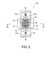
formed integral with the hinge springs 62, as shown in Fig. 2. The
housing 63 serves as a base member, on which the other components of the
actuator 60 are arranged. One part of the housing 63 constitutes the lens
holder 51 as mentioned above with reference to Fig. 1. The housing 63 is
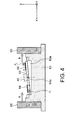
formed with a concave portion 63a, which is shown in Figs. 3 and 4. The
metal plate 61 is suspended from the housing 63 by means of the hinge
springs 62 so that the metal plate 61 is able to rotate within the concave
portion with no contact with the housing 63, as best shown in Fig. 3. As
far as the metal plate 61 can rotate, it can be held or supported by the
housing 63 by the use of any other means.
As shown in Fig. 2, the rotation axis 61a of the metal plate 61
extends in a Y-direction. As shown in Figs. 3 and 4, the mirror 40 is
disposed and fixed on a surface of the metal plate 61. As shown in Fig. 2,
the position of the mirror 40 is a center of the metal plate 61 in this
embodiment so that the mirror 40 is arranged on the rotation axis 61a of the
metal plate 61. Under the initial state, the metal plate 61 is generally
perpendicular to a Z-direction, which is perpendicular to the Y-direction, so
that the mirror 40 is also generally perpendicular to the Z-direction under
the initial state. The Z-direction is also a direction along which the
incoming light beam is launched on the mirror 40 from the incoming fiber
10.
As best shown in Fig. 2, the hinge springs 62 are positioned at the
opposite ends of the metal plate 61 in the Y-direction. Each of the hinge
springs 62 has a symmetrical shape with respect to the rotation axis 61a so
that a linear movement can be ensured upon the rotation of the metal plate
61.
As shown in Fig. 2, the coil 64 is disposed and fixed on the metal
plate 61, especially, on the same surface as the mirror 40 disposed. The
coil 64 is an air-core coil, which has a center on the rotation axis 61 a of the
metal plate 61. The coil 64 surrounds the mirror 40 in a plane parallel to
the metal plate 61. The coil 64 is formed by winding a coil line, which
has an adhesive layer as its outermost layer so that the coil line has a self-welding
function. In addition, the coil line further has an insulation
coating layer as its layer inner-next to the outermost layer, so that the
neighboring line portions are prevented from being short-circuited
electrically when the wound coil 64 is formed. The insulation coating
layer provides a desirable insulation function even if its thickness is several
µm. In addition, because the line can be wound thickly, the coil 64 can
provide a large Lorentz force for its size when a driving current is supplied
to the coil 64 as mentioned afterwards. The coil 64 may be wound in the
form of one turn or several turns and may be arranged on a surface opposite
to the surface where the mirror 40 is arranged. The coil 64 may be formed
by using a bobbin or a similar tool which can keep the wound form of the
coil 64.
Because the coil 64 and the mirror 40 are fixed on the metal plate
61, the coil 64 and the mirror 40 rotate together with the metal plate 61
when the metal plate 61 rotates, and vice versa. In this embodiment, the
coil 64 rotates in accordance with the Lorentz force, and the metal plate 61
and the mirror 40 rotate accordingly. To produce the Lorentz force, the
coil 64 is supplied with the driving current. To this end, the terminals 66
are provided for the housing 63, being insulated from each other. The
terminals 66 are electrically connected to the respective ends 64a, 64b of
the coil 64. In this embodiment, the terminal is arranged in the Y-direction,
i.e. a direction along the rotation axis 61 a.
As shown in Figs. 2 and 4, the permanent magnets 65 are fixed to
the housing 63. For example, a ferritic permanent magnet or a rare earth
permanent magnet can be used as the permanent magnet 65. The
permanent magnets 65 are arranged so that the coil 64 is placed between
the permanent magnets 65 in an X-direction perpendicular to the Y and the
Z-directions. The permanent magnets 65 generate predetermined
magnetic flux density B, which has a vector along the X-direction in this
embodiment. In other words, the predetermined magnetic flux density B
is perpendicular to the rotation axis 61a.
As shown in Fig. 4, when the driving current is supplied for the coil
64 under the circumstance where the predetermined magnetic flux density
B caused by the permanent magnets 65 is applied to the coil 64, the coil 64
receives the Lorentz force FL and thereby are rotated. When the coil 64
rotates, the metal plate 61 and the mirror 40 rotate accordingly, so that the
angle of reflection at the mirror 40 can be adjusted. The angle adjustment
linearly responds to the change of the driving current. Thus, the variable
optical attenuator 100 of the first embodiment can provide an easy
operation on the adjustment of the angle of reflection at the mirror 40 and
on the adjustment of the light intensity attenuation amount, accordingly.
Next explanation will be directed to a manufacturing process of the
actuator 60 with the mirror 40.
The metal plate 61 is formed in a predetermined shape by pressing
and etching a flexible metal material, which can provide a spring force. In
this embodiment, the metal plate 61 is made of phosphor bronze.
To form the coil 64, the above-mentioned self-welding coil line is
wound around a coil winder or an arbor which has a shape of the air-core
area of the coil 64. Next, the wound coil line is supplied with warm air so
that the self-welding function makes and fixes the form of the coil 64.
The mirror 40 is formed by sputtering gold on the base material.
At that time, Ti, Cr, Ta or the like is used as an adhesive seed layer. After
the sputtering process, a cutting process is carried out so that the mirror 40
of a predetermined shape can be obtained.
The coil 64 is fixed on the metal plate 61 by the use of an adhesive
agent or by welding. Likewise, the mirror 40 is fixed on the metal plate
61 by the use of an adhesive agent or by welding. After that, the hinge
springs 62 are connected to the housing 63 by the use of an adhesive agent
or by welding so that the metal plate 61 is held by the housing 63. Finally,
the permanent magnets 65 are fixed to the housing 63 by the use of an
adhesive layer or welding.
Thus, the manufacturing of the actuator 60 with the mirror 40 is
made of the respective fabrication processes of the components and the
simple assembly process thereof. Therefore, the actuator 60 of the present
embodiment can be manufactured easily so that the variable optical
attenuator 100 of the present embodiment is suitable for mass-production.
To verify optical properties of the variable optical attenuator
according to the first embodiment, some samples were manufactured, and
their properties were measured.
Sizes of the sample were as follows.
In the actuator 60, the length of the metal plate 61 is 6-9 mm, the
width thereof is 5-7 mm, and the thickness thereof is 0.04-0.1mm. The
length of the hinge spring 62 is 0.8-2.0 mm, and the width thereof is 0.1-0.25
mm. The length of the air-core area of the coil 64 is 1.5-2.5 mm, and
the width thereof is 0.5-1.0 mm. The length of the external form of the
coil 64 is 4-5 mm, and the width thereof is 3-5 mm. The length of the
mirror 40 is 0.7-1 mm, and the width thereof is 0.7-1 mm. The thickness
of the base material of the mirror 40 is 0.05-0.3 mm, and the thickness of
the gold layer formed on the base material is 0.02-0.05 mm.
The length of each of the permanent magnets is 6-10 mm, the width
thereof is 0.5-2 mm, and the thickness thereof is 0.5-2 mm. The total of
the diameters of the first and the second optical fibers is 1.0-2.0 mm, and
the length thereof is 5-10 mm. The length of the lens is 3.0-4.5 mm, and
the outer diameter thereof is 3.0-4.5 mm. The length of the variable
optical attenuator 100 is 18-20 mm, the width thereof is 13-17 mm, and the
height thereof is 8-12 mm.
The measurements were carried out on the samples' optical
properties. When the driving current of the coil 64 was 10 mA, the optical
loss was 4.3dB. When the driving current was 20 mA, the optical loss
was 14.0 dB. When driving current was 30 mA, the optical loss was 25.6
dB. When the driving current was 35 mA, the optical loss was 31.9 dB.
Thus, the attenuation amount at the variable optical attenuator responded
linearly to the change of the driving current supplied for the coil 64.
In addition, it was verified that the actuator 60 could work without
any damages until it was used two hundred million more times.
With reference to Figs. 5 and 6, a variable optical attenuator
according to a second embodiment of the present invention is similar to the
first embodiment expect for the electrical connections between the ends
64a, 64b of the coil 64 and the terminals 66.
According to the first embodiment, ends 64a, 64b are directly
connected to the terminals 66. On the other hand, according to the second
embodiment, two intermediate electrodes 67 are provided on the metal
plate 5, as shown in Figs. 5 and 6.
The intermediate electrodes 67 are electrically insulated from each
other, while electrically connected to the ends 64a, 64b by soldering or by
welding.
The intermediate electrodes 67 are also electrically connected to the
terminals 66 by using conductive patterns 68 which are formed on the
metal plate 61 via an insulation layer 69. With this structure, the ends 64a,
64b are fixed to and connected to the metal plate 61 so that almost all the
mechanical stress, which might occur at the ends 64a, 64b upon the
operation of the actuator 60 in the first embodiment, can be solved.
Therefore, the connection reliability of the ends 64a, 64b of the coil 64 to
the terminals 66 increases.
The actuator 60 according to the second embodiment can be
manufactured as described below. The manufacturing method of the
actuator 60 is almost the same as the first embodiment, but differs from the
first embodiment in that the metal plate 61 is formed by the use of
lithography technique and etching process.
For example, the metal plate 61 is made of phosphor bronze. On
one surface of the phosphor bronze plate, the insulation layer 69 is formed.
For example, the insulation layer 69 is made of photosensitive resin. On
the other surface of the phosphor bronze plate, a protection film is formed.
The lithography process is carried out on the photosensitive resin so that
the external form of the metal plate 61 and the hinge springs 62 is formed.
By using a metal mask which has a negative shape of the intermediate
electrodes 67 and the conductive patterns 68, conductive materials are
sputtered on the insulation layer 69. After that, the metal plate 61 is
formed by etching with a predetermined etchant against phosphor bronze.
Then, the protection film is removed by the use of a predetermined etchant
for the protection film. The metal plate 61 is fitted to the housing 63
while the conductive patterns 68 are electrically connected to the terminals
66.
With reference to Figs. 7 and 8, a variable optical attenuator device
200 according to a third embodiment of the present invention is comprised
of a plurality of variable optical attenuators 100, each of which is explained
in the first or the second embodiment. In other words, a plurality of
attenuation functions are integrated into the variable optical attenuator
device 200 of the present embodiment.
In more detail, a plurality of metal plates 61 are arranged on a
single housing 63. On each of the metal plates 61, the mirror 40 and the
coil 64 are arranged as described in the first or the second embodiment.
Each of the permanent magnets 651, 652, 653, 654 is used in common
to the variable optical attenuators 100. For example, only one set of
permanent magnets 65 may be used. In this case, all of the metal plates
61 each mounting the mirror 40 and the coil 64 are placed between the set
of permanent magnets 65.
The above-mentioned embodiments can be modified within the
scope of the present invention. For example, TEC (Thermally-diffused
Expanded Core) fibers can be used as the incoming and the outgoing fibers
10, 20. In this case, the lens 50 can be omitted.
On the both surfaces of the metal plate 61, two coils 64 may be
provided. In the case of two coils 64, a larger Lorentz force can be
obtained.
The coil 64 may be disposed on a surface of the metal plate 61,
which is opposite to the other surface where the mirror 40 is fixed. This
arrangement of the coil 64 and the mirror 40 on different surfaces of the
metal plate 61 can provide flexibility on design.
Claims (11)
- A variable optical attenuator (100) which comprises an incoming fiber (10) for propagating an incoming light beam, a mirror (40) for reflecting the incoming light beam as a reflected light beam, an outgoing fiber (20) for propagating as an outgoing light beam at least one part of the reflected light beam, and an actuator (60) for rotating the mirror (40) so as to vary light intensity of the outgoing light beam, wherein the actuator (60) comprises:a plate (61) mounting thereon the mirror (40);a coil (64) disposed on the plate (61);a housing (63) supporting the plate (61) so that the plate (61) is able to rotate around a rotation axis (61a), which is included on a predetermined plane; anda permanent magnet (65) which is fixed on the housing (63) and generates predetermined magnetic flux density (B) along the predetermined plane.
- The variable optical attenuator (100) according to claim 1, wherein the predetermined magnetic flux density (B) is substantially perpendicular to the rotation axis (61a), and/or
wherein the rotation axis (61a) passes through a center of the coil (64), and/or
wherein, when a driving current is supplied to the coil (64), the coil (64) rotates in accordance with a Lorentz force (FL) caused by the driving current and the predetermined magnetic flux density (B) so that the plate (61) rotates, and thereby, an attenuation amount linearly responds to the driving current supplied to the coil (64). - The variable optical attenuator (100) according to claim 1 or 2, wherein the coil (64) is an air-core coil, preferably, formed of a turned coil material which has a self-welding function, and/or
wherein the coil (64) surrounds the mirror (40). - The variable optical attenuator (100) according to one of claims 1 to 3, wherein: the plate (61) is a metal plate which is formed integral with two hinge springs (62); and the hinge springs (62) are positioned at opposite ends of the metal plate (61) in a direction along the rotation axis (61a) and are suspended from the housing (63), preferably, each of the hinge springs (62) has a symmetrical shape with respect to the rotation axis (61a).
- The variable optical attenuator (100) according to one of claims 1 to 4, further comprising a lens (50) which is disposed between an end portion (11) of the incoming fiber (10) and the mirror (40) and between an end portion (21) of the outgoing fiber (20) and the mirror (40).
- The variable optical attenuator (100) according to one of claims 1 to 4, wherein the incoming and the outgoing fibers (10, 20) are made of TEC (Thermally-diffused Expanded Core) fibers, respectively.
- The variable optical attenuator (100) according to one of claims 1 to 6, wherein the housing (63) is provided with two terminals (66) which are electrically connected to two ends (64a, 64b) of the coil (64), preferably, via two conductive patterns (68) and two intermediate electrodes (67), wherein: the intermediate electrodes (67) are formed on the plate (61) and are electrically connected to the respective terminals (66) by the respective conductive patterns (68), while electrically connected to the respective ends (64a, 64b) of the coil (64); and a pair of the conductive pattern (68) and the intermediate electrode (67) is electrically insulated from the other pair of the conductive pattern (68) and the intermediate electrode (67).
- The variable optical attenuator (100) according to one of claims 1 to 7, wherein the plate (61) has two surfaces, on one of which the mirror (40) and the coil (64) are disposed together, or
wherein the plate (61) has two surfaces, on one of which the mirror (40) is disposed, while the coil (64) is disposed on the other surface of the plate (61). - The variable optical attenuator (100) according to one of claims 1 to 7, wherein the coil (64) is comprised of two coil components, and the plate (61) has two surfaces on both of which the respective coil components are disposed.
- The variable optical attenuator (100) according to one of claims 1 to 9, further comprising a single ferrule (30), within which end portions (11, 21) and portions (12,22) near thereto of the incoming and the outgoing fibers (10, 20) are fixed.
- A variable optical attenuator device (200) comprising a plurality of variable optical attenuators (100) as claimed in one of claims 1 to 10, wherein the permanent magnet (651, 652, 653, 654) is used in common to at least two of the variable optical attenuators (100).
Applications Claiming Priority (2)
| Application Number | Priority Date | Filing Date | Title |
|---|---|---|---|
| JP2002343581 | 2002-11-27 | ||
| JP2002343581A JP2004177649A (en) | 2002-11-27 | 2002-11-27 | Variable light attenuator |
Publications (1)
| Publication Number | Publication Date |
|---|---|
| EP1426797A1 true EP1426797A1 (en) | 2004-06-09 |
Family
ID=32310646
Family Applications (1)
| Application Number | Title | Priority Date | Filing Date |
|---|---|---|---|
| EP03027332A Withdrawn EP1426797A1 (en) | 2002-11-27 | 2003-11-26 | Variable optical attenuator |
Country Status (5)
| Country | Link |
|---|---|
| US (1) | US6950596B2 (en) |
| EP (1) | EP1426797A1 (en) |
| JP (1) | JP2004177649A (en) |
| KR (1) | KR20040047604A (en) |
| CN (1) | CN1503023A (en) |
Families Citing this family (6)
| Publication number | Priority date | Publication date | Assignee | Title |
|---|---|---|---|---|
| KR100587327B1 (en) * | 2003-10-13 | 2006-06-08 | 엘지전자 주식회사 | Variable optical attenuator |
| FR2951713B1 (en) * | 2009-10-27 | 2012-04-13 | Centre Nat Rech Scient | MICRO-SHUTTER WITH ELECTROMAGNETIC ACTUATION |
| CN104166231B (en) * | 2014-08-12 | 2016-04-13 | 中国科学院上海光学精密机械研究所 | Blade inserting tunable laser attenuating device |
| CN104614854B (en) * | 2015-03-03 | 2018-11-02 | 四川飞阳科技有限公司 | Adjustable optical attenuator |
| US10514607B1 (en) * | 2018-08-28 | 2019-12-24 | Taiwan Semiconductor Manufacturing Co., Ltd. | Radiation source supply system for lithographic tools |
| CN114373786A (en) * | 2020-10-14 | 2022-04-19 | Oppo广东移动通信有限公司 | Display device and electronic apparatus |
Citations (5)
| Publication number | Priority date | Publication date | Assignee | Title |
|---|---|---|---|---|
| US6137941A (en) * | 1998-09-03 | 2000-10-24 | Lucent Technologies, Inc. | Variable optical attenuator |
| CA2307251A1 (en) * | 1999-04-30 | 2000-10-30 | Jds Uniphase Inc. | Back-reflecting optical attenuator |
| US20020018615A1 (en) * | 1998-06-05 | 2002-02-14 | Herzel Laor | Optical switching apparatus |
| US20020130561A1 (en) * | 2001-03-18 | 2002-09-19 | Temesvary Viktoria A. | Moving coil motor and implementations in MEMS based optical switches |
| US6483962B1 (en) * | 2000-05-24 | 2002-11-19 | Vlad J. Novotny | Optical cross connect switching array system with optical feedback |
Family Cites Families (7)
| Publication number | Priority date | Publication date | Assignee | Title |
|---|---|---|---|---|
| US18615A (en) * | 1857-11-10 | Revolving snow-excavator for railroads | ||
| US130561A (en) * | 1872-08-20 | Improvement in truss-bridges | ||
| US164997A (en) * | 1875-06-29 | Improvement -in brick a | ||
| JP3132417B2 (en) * | 1997-05-07 | 2001-02-05 | 日本電気株式会社 | Variable optical attenuator and light source for wavelength division multiplexing optical transmission using it |
| JP2000131626A (en) | 1998-10-29 | 2000-05-12 | Nec Corp | Variable light attenuator and light attenuating method |
| CA2271159A1 (en) * | 1999-04-30 | 2000-10-30 | Jds Fitel Inc. | Optical hybrid device |
| US6625341B1 (en) * | 2000-06-12 | 2003-09-23 | Vlad J. Novotny | Optical cross connect switching array system with electrical and optical position sensitive detection |
-
2002
- 2002-11-27 JP JP2002343581A patent/JP2004177649A/en active Pending
-
2003
- 2003-11-19 US US10/716,904 patent/US6950596B2/en not_active Expired - Fee Related
- 2003-11-20 KR KR1020030082514A patent/KR20040047604A/en not_active Ceased
- 2003-11-26 EP EP03027332A patent/EP1426797A1/en not_active Withdrawn
- 2003-11-27 CN CNA2003101196514A patent/CN1503023A/en active Pending
Patent Citations (5)
| Publication number | Priority date | Publication date | Assignee | Title |
|---|---|---|---|---|
| US20020018615A1 (en) * | 1998-06-05 | 2002-02-14 | Herzel Laor | Optical switching apparatus |
| US6137941A (en) * | 1998-09-03 | 2000-10-24 | Lucent Technologies, Inc. | Variable optical attenuator |
| CA2307251A1 (en) * | 1999-04-30 | 2000-10-30 | Jds Uniphase Inc. | Back-reflecting optical attenuator |
| US6483962B1 (en) * | 2000-05-24 | 2002-11-19 | Vlad J. Novotny | Optical cross connect switching array system with optical feedback |
| US20020130561A1 (en) * | 2001-03-18 | 2002-09-19 | Temesvary Viktoria A. | Moving coil motor and implementations in MEMS based optical switches |
Also Published As
| Publication number | Publication date |
|---|---|
| US20040101245A1 (en) | 2004-05-27 |
| US6950596B2 (en) | 2005-09-27 |
| JP2004177649A (en) | 2004-06-24 |
| CN1503023A (en) | 2004-06-09 |
| KR20040047604A (en) | 2004-06-05 |
Similar Documents
| Publication | Publication Date | Title |
|---|---|---|
| US20080100898A1 (en) | Electromagnetic micro-actuator | |
| US6130984A (en) | Miniature variable optical attenuator | |
| US7027682B2 (en) | Optical MEMS switching array with embedded beam-confining channels and method of operating same | |
| US11307407B2 (en) | Two-dimensional optical scanning mirror device, manufacturing method for same, two-dimensional optical scanner and image projector | |
| CA2051943A1 (en) | Fibre optic device | |
| US6324323B1 (en) | Adhesive-free lens-attached optical fibers to optical waveguide packaging system | |
| US5325456A (en) | Optical isolator in an optical fiber feedthrough | |
| US6785038B2 (en) | Optical cross-connect with magnetic micro-electro-mechanical actuator cells | |
| US6950596B2 (en) | Variable optical attenuator | |
| JP3900301B2 (en) | Light switch | |
| EP1299761A2 (en) | Optical mems switching array with embedded beam-confining channels and method of operating same | |
| US6720682B2 (en) | Actuator assembly for tilting a mirror or like object | |
| US6636683B2 (en) | Variable optical attenuator | |
| US6995894B2 (en) | Micromirror in cross-connect switch for optical communication system and method for fabricating the same | |
| US20030006360A1 (en) | Gimbal for supporting a moveable mirror | |
| US4265543A (en) | Kerr effect apparatus | |
| JP3859120B2 (en) | Light switch | |
| Nagaoka et al. | Compact optomechanical switches and their applications in optical communication and testing systems | |
| US6606446B1 (en) | Miniature variable attenuator | |
| US20030156816A1 (en) | Variable optical attenuation collimator with controllable light blocking mechanisms | |
| US7013075B2 (en) | Variable optical attenuator | |
| Nagaoka | Fabrication of micro-pipes and their applications to single-mode fiber switching and splicing | |
| JP2002122798A (en) | Moving element position changeover device, optical switch and method of manufacturing moving element housing structure | |
| Nagaoka | Optomechanical switches for fiber optic communication systems | |
| Nagaoka | Compact latching type PANDA fiber switch |
Legal Events
| Date | Code | Title | Description |
|---|---|---|---|
| PUAI | Public reference made under article 153(3) epc to a published international application that has entered the european phase |
Free format text: ORIGINAL CODE: 0009012 |
|
| AK | Designated contracting states |
Kind code of ref document: A1 Designated state(s): AT BE BG CH CY CZ DE DK EE ES FI FR GB GR HU IE IT LI LU MC NL PT RO SE SI SK TR |
|
| AX | Request for extension of the european patent |
Extension state: AL LT LV MK |
|
| 17P | Request for examination filed |
Effective date: 20041209 |
|
| AKX | Designation fees paid |
Designated state(s): DE FR GB IT |
|
| 17Q | First examination report despatched |
Effective date: 20050126 |
|
| STAA | Information on the status of an ep patent application or granted ep patent |
Free format text: STATUS: THE APPLICATION IS DEEMED TO BE WITHDRAWN |
|
| 18D | Application deemed to be withdrawn |
Effective date: 20050607 |