EP1426730A2 - Messvorrichtung der relativen Positionen von elektromagnetischen Wellen emittierenden Objekten - Google Patents
Messvorrichtung der relativen Positionen von elektromagnetischen Wellen emittierenden Objekten Download PDFInfo
- Publication number
- EP1426730A2 EP1426730A2 EP03292854A EP03292854A EP1426730A2 EP 1426730 A2 EP1426730 A2 EP 1426730A2 EP 03292854 A EP03292854 A EP 03292854A EP 03292854 A EP03292854 A EP 03292854A EP 1426730 A2 EP1426730 A2 EP 1426730A2
- Authority
- EP
- European Patent Office
- Prior art keywords
- telescope
- afocal
- focusing
- combiner
- telescopes
- Prior art date
- Legal status (The legal status is an assumption and is not a legal conclusion. Google has not performed a legal analysis and makes no representation as to the accuracy of the status listed.)
- Withdrawn
Links
Images
Classifications
-
- G—PHYSICS
- G01—MEASURING; TESTING
- G01B—MEASURING LENGTH, THICKNESS OR SIMILAR LINEAR DIMENSIONS; MEASURING ANGLES; MEASURING AREAS; MEASURING IRREGULARITIES OF SURFACES OR CONTOURS
- G01B9/00—Measuring instruments characterised by the use of optical techniques
- G01B9/06—Measuring telescopes
Definitions
- the invention relates to a device for measuring relative position of wave emitting objects electromagnetic as well as an astrometric satellite comprising a measuring device according to the invention.
- wave emitting objects electromagnetic are stars that emit light waves.
- One of the first devices proposes the assembly of a space combiner in front of an astronomical telescope.
- the combiner is consisting of a very stable assembly of two mirrors allowing to aim two directions of the sky with the same telescope. Each direction uses a half pupil of the telescope.
- the angle A between the two directions can vary from 60 ° to 120 °.
- a spatial position measurement device relative of stars designed in the mid-1980s and based on the principle of the device mentioned above, resulted in a catalog of measures which is the most accurate to date (Hipparcos catalog).
- the precision is of the order of a milliarc second or mas for "milli arc second".
- the optical combination used includes a Schmidt telescope using a blade by reflection. Given the size reduced available, the blade is cut in half and the two pieces are glued so as to make a space combiner.
- the technologies currently available require the use of a telescope with a focal length close to 50 meters and a surface half pupil of the order of a square meter.
- a telescope de Schmidt can no longer be retained because his size is equal to twice its focal length.
- a Cassegrain's telescope presents, for its part, unacceptable aberrations.
- the size of the space combiner in space requires use two large flat mirrors and the same size than the entrance pupil.
- a proposed device to achieve the precision desired by the GAIA mission is to use a Korsch telescope including a primary mirror, a secondary mirror and a tertiary mirror associated with a plane mirror placed in the exit pupil of the telescope.
- a Korsch telescope including a primary mirror, a secondary mirror and a tertiary mirror associated with a plane mirror placed in the exit pupil of the telescope.
- two beams off-axis optics with a weak field use parts without overlap of the four mentioned mirrors above and focus on the same point.
- This optical architecture is very complex and ensuring stability is not easy. It is necessary also note that the Korsch telescope shows the distortion and that the aberrations do not give a uniform diffraction spot in the field. Moreover, incidence of beams on plane detectors focal can become important at the edge of the field.
- the invention does not have these drawbacks.
- the invention relates to a device for measurement of relative position of wave emitting objects electromagnetic including a device for image formation of wave emitting objects electromagnetic.
- the imaging device includes at least two afocal telescopes, a combiner and a focusing telescope, a first telescope afocal gathering, according to a first direction, a electromagnetic wave from at least a first object emitting electromagnetic waves and at least a second afocal telescope collecting, according to a second direction, an electromagnetic wave from at least one second wave emitting object electromagnetic, electromagnetic waves collected by the first and second telescopes afocal being transmitted, via the combiner, to the focusing telescope so as to form an image of the first object and an image of the second object in the focusing plane of the focusing telescope.
- the combiner is placed in the pupils of the afocal telescopes.
- the combiner is placed in the pupil of the focusing telescope.
- the exit pupils of telescopes afocal are confused with the entrance pupil of the focusing telescope.
- the combiner consists of two plane mirrors.
- the combiner consists of two distorted mirrors to correct aberrations of the afocal telescopes and / or the telescope of focus.
- At least one afocal telescope is consisting of two concave parabolic mirrors and a field diagram, the two parabolic mirrors having a common focus, the field diaphragm and the pupil of the afocal telescope being located in the common home.
- the afocal telescope comprises a first concave mirror associated with a convex mirror for correct the field curvature and a second mirror concave.
- the focusing telescope is a Schmidt telescope by reflection.
- the focusing telescope is a Bowers-Schmidt telescope.
- the focusing telescope is a TMA telescope.
- afocal telescopes have fields different.
- the invention also relates to a satellite astrometric including a device for measuring relative position of wave emitting objects electromagnetic according to the invention.
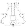
- the attached figure shows an example of device for forming images of emitting objects electromagnetic waves according to the invention.
- the device includes two afocal telescopes 1 and 2, a combiner 3 and a focusing telescope 4.
- a star E1 sends a light wave towards the afocal 1 telescope and an E2 star sends a wave light towards the afocal telescope 2.
- the beams from the afocal telescopes 1 and 2 are transmitted, via combiner 3, to the telescope of focusing 4.
- the combiner 3 reflects the two beams it receives and returns to the focusing telescope 4 two light beams substantially parallel.
- Images I1 and I2 of respective stars E1 and E2 are formed in the plane focal length of the focusing telescope.
- Each afocal telescope is made up of preferably two concave parabolic mirrors and of a field diaphragm, the two parabolic mirrors having a common focus, the field diaphragm and the afocal telescope exit pupil being located in the common home. Fields of afocal telescopes may be different if, for example, it is wished to identify the provenance of the stars.
- a variant of the afocal telescope is to replace the first parabolic mirror by a telescope of Cassegrain, i.e. an associated parabolic mirror to a hyperbolic mirror, if it is desired to correct the field curvature.
- the combiner consists, for example, of two plane mirrors.
- the combiner 3 is placed in the exit pupils of the telescopes afocal. According to a second variant of the invention, the combiner 3 is placed in the entrance pupil of the focusing telescope. According to yet another variant of the invention, the exit pupils of the afocal telescopes are preferably confused with the entrance pupil of the focusing telescope.
- the focusing telescope is preferably a Schmidt telescope by reflection.
- the telescope of focusing is a Bowers-Schmidt telescope made up of two concentric spherical mirrors associated with a reflection Schmidt blade which has half the size of the previous one and a concave focal surface. Schmidt's telescope and Bowers-Schmidt telescope affect the constant focal plane in the field.
- the focusing telescope is a TMA telescope (TMA for "Three Mirror Anastigmat" with pupil in front and, preferably, in telecentric configuration.
- the optical combination device has many advantages over combination devices optics of the prior art.
- optical elements distinct (afocal telescopes, combiner, telescope of focus), it is possible, for example, to have a more parameters to optimize the overall performance of the device.
- the different variants for realize the afocal telescopes and / or the telescope of focus allow adaptation easily to different needs such as, for example, no distortion, obtaining identical image task in the field, a defocus not introducing parallax, etc.
- magnification of telescopes afocal reduces the focal length of the focusing telescope and using the whole field potential of the focusing telescope. It is also possible to tolerate a movement of translation and / or rotation of one or more elements that make up the device (telescope focusing, afocal telescopes, combiner) without result in measurement error.
- the image forming device includes two afocal telescopes, each afocal telescope receiving light waves from a single star.
- the afocal 1 telescope receives light waves from N distinct stars
- afocal 2 telescope receives light waves from M separate stars.
- the device measurement according to the invention then makes it possible to determine the relative position of each of the N stars whose waves are received by the afocal 1 telescope with each of the M stars whose waves are received by the afocal 2 telescope. This is only for reasons of simplicity that only two stars have been shown in the figure.
- the example of measuring device shown in the figure does understands that two afocal telescopes. More general, the invention relates to a measuring device comprising at least two afocal telescopes.
Landscapes
- Physics & Mathematics (AREA)
- General Physics & Mathematics (AREA)
- Telescopes (AREA)
- Measurement Of Length, Angles, Or The Like Using Electric Or Magnetic Means (AREA)
- Lenses (AREA)
Applications Claiming Priority (2)
| Application Number | Priority Date | Filing Date | Title |
|---|---|---|---|
| FR0215431A FR2848295B1 (fr) | 2002-12-06 | 2002-12-06 | Dispositif de mesure de position relative d'objets emetteurs d'ondes electromagnetiques |
| FR0215431 | 2002-12-06 |
Publications (2)
| Publication Number | Publication Date |
|---|---|
| EP1426730A2 true EP1426730A2 (de) | 2004-06-09 |
| EP1426730A3 EP1426730A3 (de) | 2006-04-26 |
Family
ID=32310024
Family Applications (1)
| Application Number | Title | Priority Date | Filing Date |
|---|---|---|---|
| EP03292854A Withdrawn EP1426730A3 (de) | 2002-12-06 | 2003-11-17 | Messvorrichtung der relativen Positionen von elektromagnetischen Wellen emittierenden Objekten |
Country Status (2)
| Country | Link |
|---|---|
| EP (1) | EP1426730A3 (de) |
| FR (1) | FR2848295B1 (de) |
Family Cites Families (2)
| Publication number | Priority date | Publication date | Assignee | Title |
|---|---|---|---|---|
| US5485306A (en) * | 1992-11-13 | 1996-01-16 | Hughes Aircraft Company | Wide field of view multi-telescope optical multiplexed sensor |
| FR2835621B1 (fr) * | 2002-02-07 | 2004-04-16 | Astrium Sas | Instrument d'optique d'observation depuis un satellite a deux telescopes |
-
2002
- 2002-12-06 FR FR0215431A patent/FR2848295B1/fr not_active Expired - Fee Related
-
2003
- 2003-11-17 EP EP03292854A patent/EP1426730A3/de not_active Withdrawn
Also Published As
| Publication number | Publication date |
|---|---|
| FR2848295A1 (fr) | 2004-06-11 |
| FR2848295B1 (fr) | 2005-04-01 |
| EP1426730A3 (de) | 2006-04-26 |
Similar Documents
| Publication | Publication Date | Title |
|---|---|---|
| US12222459B2 (en) | Airborne topo-bathy lidar system and methods thereof | |
| FR2685499A1 (fr) | Telescope optique a champs optiques multiples, appareil optique, suiveur stellaire lie, telescope de schmidt et systeme optique. | |
| CN109870804A (zh) | 一种离轴三反五通道可见红外成像与激光接收光学系统 | |
| FR2525352A1 (fr) | Optique de champ refroidie pour telescopes a infrarouge | |
| EP3336594B1 (de) | Kompaktes teleskop, das eine vielzahl von brennweiten aufweist, die durch asphärische optische komponenten kompensiert wird | |
| EP0353138B1 (de) | Multispektrales Spiegelgerät | |
| CN109239916A (zh) | 基于施密特望远镜和奥夫纳分光的高光谱成像仪光学系统 | |
| EP3084507A1 (de) | Optisches bildgebungsmodul mit hyper-hemisphärischem feld und kontrollierter verzerrung sowie kompatibilität mit einer externen umgebung | |
| Schmidt et al. | Optical design concept for the Giant Magellan Telescope Multi-object Astronomical and Cosmological Spectrograph (GMACS) | |
| FR3012603A1 (fr) | Spectrometre a grand champ telecentrique, notamment a matrice de mems | |
| EP3489152B1 (de) | Beobachtungsinstrument mit einem spiegel-autokollimator, der an einem sternsucher montiert ist | |
| EP1426730A2 (de) | Messvorrichtung der relativen Positionen von elektromagnetischen Wellen emittierenden Objekten | |
| EP1445578A1 (de) | Verbesserte Vorrichtung zur astromerischen Messung mit zwei Teleskopen, wovon eines Astromerisch ist | |
| Da Deppo et al. | Optical performance of the wide-angle camera for the Rosetta mission: preliminary results | |
| CN103335816A (zh) | 组合多孔径闪耀和差分图像运动光学湍流传感器及方法 | |
| Manhart | A conceptual optical design of the ASCENDS space-based LIDAR receiver | |
| EP0614103B1 (de) | Infrarotfernrohr mit Schwingspiegel | |
| Muslimov et al. | A pyramid-based adaptive optics for the high-resolution echelle spectrograph at SAO RAS 6-m telescope | |
| EP1376101A1 (de) | Vorrichtung zur Messung der photometrischen Eigenschaften eines Materials | |
| CN121048749A (zh) | 一种紧凑型高光谱成像仪光学系统及其成像方法 | |
| FR3141450A1 (fr) | Télescope de Schmidt à performances améliorées, dispositifs et procédé de détection associés | |
| Liu et al. | Research on design method of spaceborne imaging spectrometer system based on telecentric optical system | |
| JPH09280950A (ja) | 広視野画像分光器 |
Legal Events
| Date | Code | Title | Description |
|---|---|---|---|
| PUAI | Public reference made under article 153(3) epc to a published international application that has entered the european phase |
Free format text: ORIGINAL CODE: 0009012 |
|
| AK | Designated contracting states |
Kind code of ref document: A2 Designated state(s): AT BE BG CH CY CZ DE DK EE ES FI FR GB GR HU IE IT LI LU MC NL PT RO SE SI SK TR |
|
| AX | Request for extension of the european patent |
Extension state: AL LT LV MK |
|
| PUAL | Search report despatched |
Free format text: ORIGINAL CODE: 0009013 |
|
| AK | Designated contracting states |
Kind code of ref document: A3 Designated state(s): AT BE BG CH CY CZ DE DK EE ES FI FR GB GR HU IE IT LI LU MC NL PT RO SE SI SK TR |
|
| AX | Request for extension of the european patent |
Extension state: AL LT LV MK |
|
| 17P | Request for examination filed |
Effective date: 20061026 |
|
| 17Q | First examination report despatched |
Effective date: 20061205 |
|
| AKX | Designation fees paid |
Designated state(s): AT BE BG CH CY CZ DE DK EE ES FI FR GB GR HU IE IT LI LU MC NL PT RO SE SI SK TR |
|
| RAP1 | Party data changed (applicant data changed or rights of an application transferred) |
Owner name: ALCATEL LUCENT |
|
| RAP1 | Party data changed (applicant data changed or rights of an application transferred) |
Owner name: ALCATEL LUCENT |
|
| STAA | Information on the status of an ep patent application or granted ep patent |
Free format text: STATUS: THE APPLICATION IS DEEMED TO BE WITHDRAWN |
|
| 18D | Application deemed to be withdrawn |
Effective date: 20120417 |