EP1426721B1 - Element for heat exchanger - Google Patents
Element for heat exchanger Download PDFInfo
- Publication number
- EP1426721B1 EP1426721B1 EP03025115A EP03025115A EP1426721B1 EP 1426721 B1 EP1426721 B1 EP 1426721B1 EP 03025115 A EP03025115 A EP 03025115A EP 03025115 A EP03025115 A EP 03025115A EP 1426721 B1 EP1426721 B1 EP 1426721B1
- Authority
- EP
- European Patent Office
- Prior art keywords
- support plate
- foil
- heat exchanger
- longitudinal portions
- heat conducting
- Prior art date
- Legal status (The legal status is an assumption and is not a legal conclusion. Google has not performed a legal analysis and makes no representation as to the accuracy of the status listed.)
- Expired - Lifetime
Links
- 239000011888 foil Substances 0.000 claims abstract description 43
- RYGMFSIKBFXOCR-UHFFFAOYSA-N Copper Chemical compound [Cu] RYGMFSIKBFXOCR-UHFFFAOYSA-N 0.000 claims abstract description 10
- 229910052802 copper Inorganic materials 0.000 claims abstract description 10
- 239000010949 copper Substances 0.000 claims abstract description 10
- 229910052782 aluminium Inorganic materials 0.000 claims abstract description 8
- XAGFODPZIPBFFR-UHFFFAOYSA-N aluminium Chemical compound [Al] XAGFODPZIPBFFR-UHFFFAOYSA-N 0.000 claims abstract description 8
- 238000010438 heat treatment Methods 0.000 claims abstract description 5
- 229910052751 metal Inorganic materials 0.000 claims description 23
- 239000002184 metal Substances 0.000 claims description 23
- 239000012790 adhesive layer Substances 0.000 claims description 14
- 239000010410 layer Substances 0.000 claims description 12
- 239000000853 adhesive Substances 0.000 claims description 10
- 230000001070 adhesive effect Effects 0.000 claims description 10
- CWYNVVGOOAEACU-UHFFFAOYSA-N Fe2+ Chemical compound [Fe+2] CWYNVVGOOAEACU-UHFFFAOYSA-N 0.000 claims description 9
- 230000002093 peripheral effect Effects 0.000 claims description 8
- 125000006850 spacer group Chemical group 0.000 claims description 7
- 238000000034 method Methods 0.000 claims description 5
- 238000004519 manufacturing process Methods 0.000 claims description 4
- 238000000465 moulding Methods 0.000 claims description 2
- 239000004411 aluminium Substances 0.000 claims 1
- XEEYBQQBJWHFJM-UHFFFAOYSA-N Iron Chemical compound [Fe] XEEYBQQBJWHFJM-UHFFFAOYSA-N 0.000 abstract description 8
- 238000001816 cooling Methods 0.000 abstract description 6
- 229910052742 iron Inorganic materials 0.000 abstract description 4
- 239000000463 material Substances 0.000 abstract description 3
- 239000012530 fluid Substances 0.000 abstract description 2
- 229910052602 gypsum Inorganic materials 0.000 abstract 1
- 239000010440 gypsum Substances 0.000 abstract 1
- 229910001234 light alloy Inorganic materials 0.000 abstract 1
- 239000002313 adhesive film Substances 0.000 description 13
- 230000001681 protective effect Effects 0.000 description 10
- WYTGDNHDOZPMIW-RCBQFDQVSA-N alstonine Natural products C1=CC2=C3C=CC=CC3=NC2=C2N1C[C@H]1[C@H](C)OC=C(C(=O)OC)[C@H]1C2 WYTGDNHDOZPMIW-RCBQFDQVSA-N 0.000 description 3
- 238000010276 construction Methods 0.000 description 2
- 239000003292 glue Substances 0.000 description 2
- 238000009434 installation Methods 0.000 description 2
- 229910000831 Steel Inorganic materials 0.000 description 1
- 150000001875 compounds Chemical class 0.000 description 1
- 230000000994 depressogenic effect Effects 0.000 description 1
- 238000010586 diagram Methods 0.000 description 1
- 238000005304 joining Methods 0.000 description 1
- 238000004080 punching Methods 0.000 description 1
- 238000007493 shaping process Methods 0.000 description 1
- 239000002689 soil Substances 0.000 description 1
- 229910000679 solder Inorganic materials 0.000 description 1
- 239000004834 spray adhesive Substances 0.000 description 1
- 239000010959 steel Substances 0.000 description 1
Images

Classifications
-
- F—MECHANICAL ENGINEERING; LIGHTING; HEATING; WEAPONS; BLASTING
- F28—HEAT EXCHANGE IN GENERAL
- F28F—DETAILS OF HEAT-EXCHANGE AND HEAT-TRANSFER APPARATUS, OF GENERAL APPLICATION
- F28F1/00—Tubular elements; Assemblies of tubular elements
- F28F1/10—Tubular elements and assemblies thereof with means for increasing heat-transfer area, e.g. with fins, with projections, with recesses
- F28F1/12—Tubular elements and assemblies thereof with means for increasing heat-transfer area, e.g. with fins, with projections, with recesses the means being only outside the tubular element
- F28F1/14—Tubular elements and assemblies thereof with means for increasing heat-transfer area, e.g. with fins, with projections, with recesses the means being only outside the tubular element and extending longitudinally
- F28F1/22—Tubular elements and assemblies thereof with means for increasing heat-transfer area, e.g. with fins, with projections, with recesses the means being only outside the tubular element and extending longitudinally the means having portions engaging further tubular elements
-
- F—MECHANICAL ENGINEERING; LIGHTING; HEATING; WEAPONS; BLASTING
- F24—HEATING; RANGES; VENTILATING
- F24D—DOMESTIC- OR SPACE-HEATING SYSTEMS, e.g. CENTRAL HEATING SYSTEMS; DOMESTIC HOT-WATER SUPPLY SYSTEMS; ELEMENTS OR COMPONENTS THEREFOR
- F24D3/00—Hot-water central heating systems
- F24D3/12—Tube and panel arrangements for ceiling, wall, or underfloor heating
- F24D3/16—Tube and panel arrangements for ceiling, wall, or underfloor heating mounted on, or adjacent to, a ceiling, wall or floor
- F24D3/165—Suspended radiant heating ceiling
-
- F—MECHANICAL ENGINEERING; LIGHTING; HEATING; WEAPONS; BLASTING
- F28—HEAT EXCHANGE IN GENERAL
- F28D—HEAT-EXCHANGE APPARATUS, NOT PROVIDED FOR IN ANOTHER SUBCLASS, IN WHICH THE HEAT-EXCHANGE MEDIA DO NOT COME INTO DIRECT CONTACT
- F28D1/00—Heat-exchange apparatus having stationary conduit assemblies for one heat-exchange medium only, the media being in contact with different sides of the conduit wall, in which the other heat-exchange medium is a large body of fluid, e.g. domestic or motor car radiators
- F28D1/02—Heat-exchange apparatus having stationary conduit assemblies for one heat-exchange medium only, the media being in contact with different sides of the conduit wall, in which the other heat-exchange medium is a large body of fluid, e.g. domestic or motor car radiators with heat-exchange conduits immersed in the body of fluid
- F28D1/04—Heat-exchange apparatus having stationary conduit assemblies for one heat-exchange medium only, the media being in contact with different sides of the conduit wall, in which the other heat-exchange medium is a large body of fluid, e.g. domestic or motor car radiators with heat-exchange conduits immersed in the body of fluid with tubular conduits
- F28D1/047—Heat-exchange apparatus having stationary conduit assemblies for one heat-exchange medium only, the media being in contact with different sides of the conduit wall, in which the other heat-exchange medium is a large body of fluid, e.g. domestic or motor car radiators with heat-exchange conduits immersed in the body of fluid with tubular conduits the conduits being bent, e.g. in a serpentine or zig-zag
- F28D1/0477—Heat-exchange apparatus having stationary conduit assemblies for one heat-exchange medium only, the media being in contact with different sides of the conduit wall, in which the other heat-exchange medium is a large body of fluid, e.g. domestic or motor car radiators with heat-exchange conduits immersed in the body of fluid with tubular conduits the conduits being bent, e.g. in a serpentine or zig-zag the conduits being bent in a serpentine or zig-zag
- F28D1/0478—Heat-exchange apparatus having stationary conduit assemblies for one heat-exchange medium only, the media being in contact with different sides of the conduit wall, in which the other heat-exchange medium is a large body of fluid, e.g. domestic or motor car radiators with heat-exchange conduits immersed in the body of fluid with tubular conduits the conduits being bent, e.g. in a serpentine or zig-zag the conduits being bent in a serpentine or zig-zag the conduits having a non-circular cross-section
-
- F—MECHANICAL ENGINEERING; LIGHTING; HEATING; WEAPONS; BLASTING
- F28—HEAT EXCHANGE IN GENERAL
- F28F—DETAILS OF HEAT-EXCHANGE AND HEAT-TRANSFER APPARATUS, OF GENERAL APPLICATION
- F28F9/00—Casings; Header boxes; Auxiliary supports for elements; Auxiliary members within casings
- F28F9/007—Auxiliary supports for elements
- F28F9/013—Auxiliary supports for elements for tubes or tube-assemblies
-
- F—MECHANICAL ENGINEERING; LIGHTING; HEATING; WEAPONS; BLASTING
- F28—HEAT EXCHANGE IN GENERAL
- F28F—DETAILS OF HEAT-EXCHANGE AND HEAT-TRANSFER APPARATUS, OF GENERAL APPLICATION
- F28F2275/00—Fastening; Joining
- F28F2275/02—Fastening; Joining by using bonding materials; by embedding elements in particular materials
- F28F2275/025—Fastening; Joining by using bonding materials; by embedding elements in particular materials by using adhesives
-
- Y—GENERAL TAGGING OF NEW TECHNOLOGICAL DEVELOPMENTS; GENERAL TAGGING OF CROSS-SECTIONAL TECHNOLOGIES SPANNING OVER SEVERAL SECTIONS OF THE IPC; TECHNICAL SUBJECTS COVERED BY FORMER USPC CROSS-REFERENCE ART COLLECTIONS [XRACs] AND DIGESTS
- Y02—TECHNOLOGIES OR APPLICATIONS FOR MITIGATION OR ADAPTATION AGAINST CLIMATE CHANGE
- Y02B—CLIMATE CHANGE MITIGATION TECHNOLOGIES RELATED TO BUILDINGS, e.g. HOUSING, HOUSE APPLIANCES OR RELATED END-USER APPLICATIONS
- Y02B30/00—Energy efficient heating, ventilation or air conditioning [HVAC]
Definitions
- the invention relates to a heat exchanger element which has a serpentine tubular pipe register which can be charged with a cooling or heating medium.
- a heat exchanger element also counts through the DE 198 50 013 A1 to the state of the art. It consists of a heat-conducting foil, a serpentine tube register, a base layer of expanded metal and an adhesive film with adhesive layers arranged on both sides. All four components of the heat exchanger element must be manufactured separately and adapted to each other in order of magnitude. The adhesive film must be provided with an adhesive layer on both sides, with the adhesive layers covered with protective films until installation.
- the four components after pulling the protective film on the expanded metal side facing the adhesive film are compressed so that the adhesive film connects to the heat conduction through the recesses in the expanded metal and thereby fixes the pipe register to the base layer.
- This heat exchanger element is then connected to a construction site with a wall or ceiling side festun support plate made of metal or plasterboard, by the fact that deducted on the second side of the adhesive film, the protective film and the then exposed adhesive layer, the heat exchanger element is attached to the support plate ,
- the invention is - based on the prior art - the task of creating a heat exchanger element that is simpler in design and also easier to assemble.
- the heat exchanger element according to the invention only consists of three individual parts, namely a support plate, the tube register and a heat conducting foil. Due to the considerable reduction of the individual parts, the production and assembly costs are significantly reduced. The economy in the occupancy of ceilings and walls for the purpose of cooling or heating a room is noticeably increased.
- the fixation of a cooling or heating medium pipe register to the support plate can be effected by using a spray adhesive, with which the heat-conducting is determined under partial Umong the tube register to the support plate. It is also conceivable that the heat-conducting directly associated with an adhesive, for example in the form of only one-sided adhesive layer, which then ensures the positional fixing of the tube register when joining the heat conducting foil, pipe register and support plate.
- the tube register has a cross section with at least one flattened peripheral region. This comes into contact with the support plate and thereby causes a significantly improved heat transfer.
- the cross section may be horseshoe-shaped, oval or in particular triangular. A triangular cross section lowers the non-heat conductive area between the pipe register and the heat conducting film on the one hand and the support plate on the other hand to a minimum.
- the tube register is preferably made of copper. It is also conceivable aluminum or iron.
- the support plate can be made of plasterboard. This is usually provided with a plurality of holes for acoustic reasons. Also, support plates made of aluminum, copper or steel sheet, preferably in perforated cassette form, can be used.
- the heat-conducting foil consists of a metal foil with a single-sided adhesive layer.
- the metal foil may be formed of iron, aluminum or copper.
- the adhesive layer is also provided with a protective film.
- the heat-conducting foil can consist of iron, aluminum or copper.
- the material thickness ranges between about 15 microns and 30 microns.
- thermoelectric film An advantageous embodiment of a heat-conducting film consists in the features of claim 2. Thereafter, the heat-conducting film consists of an adhesive film with a one-sided laminated film-like layer of a non-ferrous metal, in particular aluminum or copper together. The adhesive layer on the other side of the non-ferrous metal layer is covered with a protective film before mounting the heat-conducting foil, which only has to be removed during assembly.
- the heat-conducting film consists of an adhesive film with a one-sided laminated film-like layer of a ferrous metal. On the other side then again an adhesive layer is provided with a protective film.
- a serpentine tubular register which is composed of straight lengths and each two adjacent straight lengths connecting arcuate lengths, thereby on a support plate Position fixiert that along the straight lengths strip-shaped réelleleitfolie be placed. These mecanicfolien span the straight sections of length and attach them via their adhesive layers on the support plate.
- a fleece on the support plate may be black by nature or blackened.
- a nonwoven may be black by nature or blackened.
- the variousillonleitfolien to the support plate towards colored black is particularly preferred.
- the embodiment of claim 6 also provides a pipe register which is composed of straight lengths and each two adjacent longitudinal sections connecting arcuate lengths.
- This tube register is thereby fixed in position on a support plate while securing the desired heat exchanger properties, that at least one all straight lengths and lying between the straight lengths surface portions of the support plate overlapping, extending transversely to the straight lengths extending sheet-like heat-conducting over an adhesive layer to the support plate.
- two or more web-shaped perennialierifolien be laid parallel to each other. The heat transfer is further improved in this way.
- the portions of the heat-conducting foil lying in the area of the holes are pressed into the holes , Put the pressed in sections adhere to the inner surfaces of the holes and thus increase the heat exchanging surfaces.
- the sections of the heat-conducting foil are preferably pressed into the holes with suitable spikes.
- support rails are advantageously used, which have a U-shaped cross-section and are fixed locally via suitable, usually length-adjustable support elements.
- the support plates of the heat exchanger elements are attached to these support rails, in particular screwed.
- the features of claim 8 provide that spacer strips are incorporated between the support plate and the carrier rails.
- the preferably made of plasterboard spacer strips terminate before the arcuate lengths. Since the spacer strips have the thickness of the tube register, this can consequently be easily laid over the entire surface extension of the support plate, without the support rails hinder the installation.
- a shaped body in which an engraving is incorporated from its surface, which corresponds on the one hand to the configuration and on the other hand to the cross section of the tube register.
- a heat-conducting foil is placed on the surface and the tube register is congruent to the engraving foil after removal of a protective foil covering an adhesive layer.
- the support plate is placed on the pipe register and this pressed together with the heat-conducting foil in the engraving.
- the heat-conducting foil spans the pipe register in a form-fitting manner and places it stuck to the support plate. If the pipe register still has a circular cross-section before assembly, this cross-section can be converted into the cross-section defined by the engraving in the course of assembly. So it is only a single process step required to fix the pipe register properly heat transferring to the support plate.
- the support plate is made of plasterboard and has holes, it may also be advantageous according to the features of patent claim 10 that the sections of the heat-conducting foil located in the region of the holes are pressed into the holes with a mandrel tool.
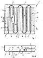
- the heat exchanger element 1 comprises a cassette-like support plate 2 made of light metal, which is composed of a bottom 3 and edge 4 of the bottom 3 vertically projecting edges.
- the support plate 2 may be formed by punching and folding a board.
- a serpentine configured tube register 6 extends from a copper tube with horseshoe-shaped cross-section.
- the tube register 6 consists of straight lengths 7 and two adjoining straight lengths 7 alternately connecting arcuate lengths 8.
- the tube register 6 is acted upon by a fluid that cools or heats the room depending on the requirements.
- the ends 9 of the tube register 6 are fluid-conductively connected to the ends of adjacent tube registers. The compounds are not shown in detail.
- each heat-conducting film 10 consists of an adhesive film 11 with a film-like layer 12 laminated on one side of a non-ferrous metal, in particular aluminum or copper. How the particular Figures 2 and 3 can be seen after the removal of a protective film, not shown, of the adhesive film 11, the heat-conducting film 10 along the straight lengths 7, this U-shaped sheathing on the inside 5 of the support plate 2 set.
- the support plate 2 of the heat exchanger element 1 is often provided with holes introduced into the bottom 3, the surface regions 15 of the inner side 5 of the bottom 3 of the support plate 2 may be covered in addition to the strip-shaped réelleleitfolien 10 with a particular black fleece 13. Black, therefore, in order to observe the heat exchanger element 1 in the direction of the arrow PF FIG. 2 to see a uniform dark background behind the holes.
- the bottom 3 of the underside facing the sauitfolien 10 are colored black.
- the tube register 6 extends over the bottom 3 of the support plate 2 so that no holes are covered.
- the tube register 6 comes with a flattened peripheral region 14 with the inside 5 of the bottom 3 of the support plate 2 in surface contact. The heat exchange is thereby improved.
- a separate strip-shaped heat-conducting film 10 is used to fix the position of the tube register 6 on the support plate 2, it can according to the dash-dotted lines in FIG. 1 It is also conceivable that the tube register 6 is fixed in position on the support plate 2 by means of at least one straight length sections 7 and the surface regions 15 of the inner side 5 of the support plate 2 lying between the straight longitudinal sections 7, extending transversely to the straight longitudinal sections 7 ,
- Such a web-shaped heat-conducting film 10a can likewise consist of an adhesive film 11 with a film-like layer 12 laminated on one side of a non-ferrous metal or of a ferrous metal.
- both a strip-shaped heat-conducting foil 10 and a web-shaped heat-conducting foil 10a consist of a metal foil with an adhesive layer applied on one side.
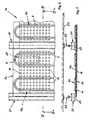
- FIGS. 6 and 7 a heat exchanger element 1a is shown having a support plate 2a made of plasterboard with a plurality of holes 16.
- a serpentine pipe register 6b is laid, which has a triangular cross-section according to FIG. 5 having.
- the position fixing of the tube register 6b on the inner side 5a takes place with the aid of a web-shaped heat-conducting foil 10a.
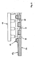
- the portions 17 of the heat-conducting foil 10 a which lie in the region of the holes 16, are pressed in ( FIG. 8 ), wherein the depressed portions 17 lie against the walls 18 of the holes 16, so that the heat exchanging surface of the heat conducting film 10 a is increased.
- the sections 17 of the heat-conducting film 10a can be pressed into the holes 16 with the aid of a dome tool 19, which likewise comes from the FIG. 8 is recognizable.
- the heat exchanger element 1a of FIGS. 6 and 7 is mounted under the inclusion of spacer strips 20 of plasterboard below parallel to the straight lengths 7 extending U-shaped mounting rails 21 made of light metal, in particular screwed.
- the spacer strips 20 have a thickness which is only slightly larger than the thickness of the tube register 6b. This construction makes it possible to easily pass the pipe register 6b even when the heat exchanger elements 1a are larger in the surface extension under proper contact with the support plate 2a, in that the spacer strips 20, which would intersect arcuate longitudinal sections 8, end shortly before the arcuate longitudinal sections 8. This is in the middle of FIG. 6 illustrated in dash-dotted lines hinted.
- the support rails 21 themselves are suspended by adjustable length support members 22 on the ceiling 23 of a room. In this way, a perfect horizontal alignment of all heat exchanger elements 1 a can be ensured ( FIG. 7 ).
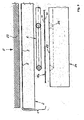
- FIG. 9 schematically illustrates the assembly of a heat exchanger element 1, which is a cassette-like support plate 2 according to the Figures 1 and 2 and a pipe register 6b having a triangular cross section corresponding to FIG FIG. 5 having.
- a molding 24 is provided, starting from its surface 25, one of the configuration and the cross section of the tube register 6 b FIG. 5 corresponding engraving 26 has.
- a web-shaped heat-conducting film 10a is then placed, which consists of an adhesive film 11 with a film-like layer 12 laminated on one side of a non-ferrous metal.
- the sheet-like layer 12 faces the surface 25.
- On the adhesive film 11 of the heat-conducting film 10a is initially still a protective film. After peeling off the protective film, the tube register 6 is congruent to the engraving 26 im Shaped body 24 placed on the thermal pad 10a.
- the support plate 2 is placed on the pipe register 6, wherein the inner side 5 of the bottom 3 of the support plate 2 comes into contact with the pipe register 6.
Abstract
Description
Die Erfindung betrifft ein Wärmeaustauscherelement, das ein mit einem Kühl- oder Heizmedium beaufschlagbares schlangenlinienförmiges Rohrregister aufweist.The invention relates to a heat exchanger element which has a serpentine tubular pipe register which can be charged with a cooling or heating medium.
Durch die
Durch die
Ferner zählt es zum Stand der Technik, Kühldecken mit eingelegten Kühlplatinen bzw. Wärmeleitelementen so zu verkleben, dass zwischen den zu verklebenden Flächen kein Klebstoff vorhanden ist und somit ein optimaler wärmeleitender Kontakt hergestellt wird (
Ein Wärmeaustauscherelement zählt auch durch die
Bei der Montage des Wärmeaustauscherelements werden die vier Bauteile nach dem Abziehen der Schutzfolie auf der dem Streckmetall zugewandten Seite der Klebefolie so zusammengedrückt, dass sich die Klebefolie mit der Wärmeleitfolie über die Ausnehmungen im Streckmetall verbindet und hierdurch das Rohrregister an der Basisschicht fixiert.When mounting the heat exchanger element, the four components after pulling the protective film on the expanded metal side facing the adhesive film are compressed so that the adhesive film connects to the heat conduction through the recesses in the expanded metal and thereby fixes the pipe register to the base layer.
Dieses Wärmeaustauscherelement wird dann auf einer Baustelle mit einer wand- oder deckenseitig festzulegenden Tragplatte aus Metall oder Gipskarton verbunden, und zwar dadurch, dass auch auf der zweiten Seite der Klebefolie die Schutzfolie abgezogen und über die dann frei liegende Klebeschicht das Wärmeaustauscherelement an der Tragplatte befestigt wird.This heat exchanger element is then connected to a construction site with a wall or ceiling side festzulegenden support plate made of metal or plasterboard, by the fact that deducted on the second side of the adhesive film, the protective film and the then exposed adhesive layer, the heat exchanger element is attached to the support plate ,
Da es sich bei einem derartigen auf einer Tragplatte angeordneten Wärmeaustauscherelement um einen ausgesprochenen Massenartikel handelt, bedeutet jedes Einzelteil und jeder Verfahrensschritt bis zur Endmontage einen erhöhten Aufwand. Dieser Aufwand ist im bekannten Fall zeit-, material- und personalintensiv.Since such a heat exchanger element arranged on a support plate is a pronounced mass-produced article, each individual part and each process step up to the final assembly means an increased outlay. This effort is time, material and labor intensive in the known case.
Der Erfindung liegt - ausgehend vom Stand der Technik - die Aufgabe zugrunde, ein Wärmeaustauscherelement zu schaffen, das einfacher aufgebaut und auch leichter zu montieren ist.The invention is - based on the prior art - the task of creating a heat exchanger element that is simpler in design and also easier to assemble.
Diese Aufgabe wird mit den im Patentanspruch 1 angegebenen Merkmalen gelöst.This object is achieved with the features specified in
Im Gegensatz zu der bekannten Bauart, die im Endmontagezustand letztlich aus insgesamt fünf Einzelteilen zusammengesetzt ist, besteht das erfindungsgemäße Wärmeaustauscherelement nur noch aus drei Einzelteilen, nämlich einer Tragplatte, dem Rohrregister und einer Wärmeleitfolie. Durch die erhebliche Reduzierung der Einzelteile wird der Fertigungs- und Montageaufwand deutlich gesenkt. Die Wirtschaftlichkeit bei der Belegung von Decken und Wänden zum Zwecke der Kühlung bzw. der Heizung eines Raums wird merklich heraufgesetzt.In contrast to the known type, which in the final assembly state is ultimately composed of a total of five individual parts, the heat exchanger element according to the invention only consists of three individual parts, namely a support plate, the tube register and a heat conducting foil. Due to the considerable reduction of the individual parts, the production and assembly costs are significantly reduced. The economy in the occupancy of ceilings and walls for the purpose of cooling or heating a room is noticeably increased.
Die Fixierung des ein Kühl- oder Heizmedium führenden Rohrregisters an der Tragplatte kann dadurch erfolgen, dass ein Sprühkleber benutzt wird, mit dem die Wärmeleitfolie unter teilweiser Umspannung des Rohrregisters an der Tragplatte festgelegt wird. Denkbar ist aber auch, dass der Wärmeleitfolie direkt ein Kleber zugeordnet ist, beispielsweise in Form einer nur einseitigen Klebeschicht, die dann beim Zusammenfügen vom Wärmeleitfolie, Rohrregister und Tragplatte die Lagefixierung des Rohrregisters gewährleistet.The fixation of a cooling or heating medium pipe register to the support plate can be effected by using a spray adhesive, with which the heat-conducting is determined under partial Umspannung the tube register to the support plate. It is also conceivable that the heat-conducting directly associated with an adhesive, for example in the form of only one-sided adhesive layer, which then ensures the positional fixing of the tube register when joining the heat conducting foil, pipe register and support plate.
Das Rohrregister besitzt einen Querschnitt mit zumindest einem abgeflachten Umfangsbereich. Dieser gelangt in Kontakt mit der Tragplatte und bewirkt dadurch einen deutlich verbesserten Wärmeübergang. Der Querschnitt kann hufeisenförmig, oval oder insbesondere dreieckförmig sein. Ein dreieckförmiger Querschnitt senkt den nicht Wärme leitenden Bereich zwischen dem Rohrregister sowie der Wärmeleitfolie einerseits und der Tragplatte andererseits auf ein Mindestmaß.The tube register has a cross section with at least one flattened peripheral region. This comes into contact with the support plate and thereby causes a significantly improved heat transfer. The cross section may be horseshoe-shaped, oval or in particular triangular. A triangular cross section lowers the non-heat conductive area between the pipe register and the heat conducting film on the one hand and the support plate on the other hand to a minimum.
Das Rohrregister besteht vorzugsweise aus Kupfer. Denkbar ist aber auch Aluminium oder Eisen.The tube register is preferably made of copper. It is also conceivable aluminum or iron.
Die Tragplatte kann aus Gipskarton bestehen. Diese ist aus akustischen Gründen in der Regel mit einer Vielzahl von Löchern versehen. Auch Tragplatten aus Aluminium, Kupfer oder Stahlblech, vorzugsweise in gelochter Kassettenform, können zum Einsatz gelangen.The support plate can be made of plasterboard. This is usually provided with a plurality of holes for acoustic reasons. Also, support plates made of aluminum, copper or steel sheet, preferably in perforated cassette form, can be used.
Die Wärmeleitfolie besteht aus einer Metallfolie mit einer einseitig aufgebrachten Klebeschicht. Die Metallfolie kann aus Eisen, Aluminium oder Kupfer gebildet sein. Die Klebeschicht ist ebenfalls mit einer Schutzfolie versehen.The heat-conducting foil consists of a metal foil with a single-sided adhesive layer. The metal foil may be formed of iron, aluminum or copper. The adhesive layer is also provided with a protective film.
Die Wärmeleitfolie kann aus Eisen, Aluminium oder Kupfer bestehen. Die Materialdicke bewegt sich zwischen etwa 15 µm und 30 µm.The heat-conducting foil can consist of iron, aluminum or copper. The material thickness ranges between about 15 microns and 30 microns.
Eine vorteilhafte Ausführungsform einer Wärmeleitfolie besteht in den Merkmalen des Patentanspruchs 2. Danach setzt sich die Wärmeleitfolie aus einer Klebefolie mit einer einseitig aufkaschierten folienartigen Schicht aus einem Nichteisenmetall, insbesondere Aluminium oder Kupfer, zusammen. Die Klebeschicht auf der anderen Seite der Nichteisenmetallschicht wird vor der Montage der Wärmeleitfolie mit einer Schutzfolie abgedeckt, die bei der Montage lediglich abgezogen werden muss.An advantageous embodiment of a heat-conducting film consists in the features of
Vorstellbar ist gemäß Patentanspruch 3 aber auch, dass die Wärmeleitfolie aus einer Klebefolie mit einer einseitig aufkaschierten folienartigen Schicht aus einem Eisenmetall besteht. Auf der anderen Seite ist dann wieder eine Klebeschicht mit einer Schutzfolie vorgesehen.It is also conceivable according to
Entsprechend den Merkmalen des Patentanspruchs 4 wird ein schlangenlinienförmiges Rohrregister, das sich aus geraden Längenabschnitten und jeweils zwei einander benachbarte gerade Längenabschnitte verbindenden bogenförmigen Längenabschnitten zusammensetzt, dadurch an einer Tragplatte lagefixiert, dass entlang der geraden Längenabschnitte streifenförmige Wärmeleitfolien platziert werden. Diese Wärmeleitfolien umspannen die geraden Längenabschnitte und legen diese über ihre Klebeschichten an der Tragplatte fest.According to the features of
Bei dieser Ausführungsform ist es dann gemäß Patentanspruch 5 sinnvoll, neben den streifenförmigen Wärmeleitfolien ein Vlies auf die Tragplatte aufzubringen. Ein solches Vlies kann von Natur aus schwarz sein oder es wird schwarz eingefärbt. Dies insbesondere deshalb, um bei der Betrachtung einer Decke oder einer Wand, die mit erfindungsgemäßen Wärmeaustauscherelementen belegt ist und bei denen die Tragplatten aus akustischen Gründen gelöchert sind, einen gleichmäßigen Hintergrund zu haben. Bevorzugt sind auch die diversen Wärmeleitfolien zur Tragplatte hin entsprechend schwarz eingefärbt.In this embodiment, it is then useful according to
Die Ausführungsform des Patentanspruchs 6 sieht ebenfalls ein Rohrregister vor, das sich aus geraden Längenabschnitten und jeweils zwei einander benachbarte Längenabschnitte verbindenden bogenförmigen Längenabschnitten zusammensetzt. Dieses Rohrregister wird dadurch unter Sicherung der gewünschten Wärmeaustauschereigenschaften auf einer Tragplatte lagefixiert, dass mindestens eine alle geraden Längenabschnitte sowie die zwischen den geraden Längenabschnitten liegenden Oberflächenbereiche der Tragplatte überdeckende, sich quer zu den geraden Längenabschnitten erstreckende bahnförmige Wärmeleitfolie über eine Klebeschicht an der Tragplatte lagefixiert wird. Je nach der Länge der geraden Längenabschnitte können auch zwei oder mehrere bahnförmige Wärmeleitfolien parallel nebeneinander verlegt werden. Die Wärmeübertragung wird auf diese Weise noch weiter verbessert.The embodiment of
Um bei einer Tragplatte mit Löchern, insbesondere aus Gipskarton, auch im Bereich der Löcher die Wärmeaustauschereigenschaften noch weiter zu erhöhen, ohne eine gute Akustik zu beeinträchtigen, sind entsprechend den Merkmalen des Patentanspruchs 7 die im Bereich der Löcher liegenden Abschnitte der Wärmeleitfolie in die Löcher gedrückt. Die eingedrückten Abschnitte legen sich an die inneren Oberflächen der Löcher und vergrößern somit die Wärme austauschenden Oberflächen. Die Abschnitte der Wärmeleitfolie werden vorzugsweise mit geeigneten Dornen in die Löcher gedrückt.In order to increase the heat exchanger properties even further in the area of the holes in a support plate with holes, in particular made of plasterboard, without impairing good acoustics, according to the features of
Zur Lagefixierung eines Wärmeaustauscherelements, insbesondere an einer Decke, werden vorteilhaft Tragschienen herangezogen, die einen U-förmigen Querschnitt aufweisen und über geeignete, zumeist längenveränderbare Tragelemente örtlich befestigt werden. Die Tragplatten der Wärmeaustauscherelemente werden an diesen Tragschienen befestigt, insbesondere geschraubt. Weist ein Wärmeaustauscherelement eine größere Flächenerstreckung auf, um einerseits die Herstellung und andererseits die Montage vor Ort zu vereinfachen, so sehen die Merkmale des Patentanspruchs 8 vor, dass zwischen die Tragplatte und die Tragschienen Distanzleisten eingegliedert werden. Die bevorzugt aus Gipskarton bestehenden Distanzleisten enden vor den bogenförmigen Längenabschnitten. Da die Distanzleisten die Dicke des Rohrregisters aufweisen, kann dieses folglich problemlos über die gesamte Flächenerstreckung der Tragplatte verlegt werden, ohne dass die Tragschienen die Verlegung behindern.To fix the position of a heat exchanger element, in particular on a ceiling, support rails are advantageously used, which have a U-shaped cross-section and are fixed locally via suitable, usually length-adjustable support elements. The support plates of the heat exchanger elements are attached to these support rails, in particular screwed. If a heat exchanger element has a larger areal extent in order to simplify the production on the one hand and the on-site assembly on the other hand, the features of claim 8 provide that spacer strips are incorporated between the support plate and the carrier rails. The preferably made of plasterboard spacer strips terminate before the arcuate lengths. Since the spacer strips have the thickness of the tube register, this can consequently be easily laid over the entire surface extension of the support plate, without the support rails hinder the installation.
Ein vorteilhaftes Verfahren zur Herstellung eines Wärmeaustauscherelements mit einem schlangenlinienförmigen Rohrregister als lagefixiertes Bestandteil einer Tragplatte aus Metall oder Gipskarton wird in den Merkmalen des Patentanspruchs 9 erblickt.An advantageous method for producing a heat exchanger element with a serpentine tube register as a position-fixed component of a support plate made of metal or plasterboard is seen in the features of
Bei diesem Verfahren wird zunächst ein Formkörper bereit gestellt, in den von seiner Oberfläche her eine Gravur eingearbeitet ist, die einerseits der Konfiguration und andererseits dem Querschnitt des Rohrregisters entspricht. Auf die Oberfläche wird eine Wärmeleitfolie gelegt und auf die Wärmeleitfolie nach Entfernung einer eine Klebeschicht abdeckenden Schutzfolie kongruent zur Gravur das Rohrregister. Danach wird die Tragplatte auf das Rohrregister gelegt und dieses gemeinsam mit der Wärmeleitfolie in die Gravur gedrückt. Die Wärmeleitfolie umspannt dadurch formschlüssig das Rohrregister und legt dieses an der Tragplatte fest. Weist das Rohrregister vor der Montage noch einen kreisrunden Querschnitt auf, kann im Zuge des Zusammenbaus dieser Querschnitt in den durch die Gravur vorgegebenen Querschnitt umgeformt werden. Es ist also nur ein einziger Verfahrensschritt erforderlich, um das Rohrregister ordnungsgemäß Wärme übertragend an der Tragplatte zu fixieren.In this method, first of all a shaped body is provided in which an engraving is incorporated from its surface, which corresponds on the one hand to the configuration and on the other hand to the cross section of the tube register. A heat-conducting foil is placed on the surface and the tube register is congruent to the engraving foil after removal of a protective foil covering an adhesive layer. Thereafter, the support plate is placed on the pipe register and this pressed together with the heat-conducting foil in the engraving. As a result, the heat-conducting foil spans the pipe register in a form-fitting manner and places it stuck to the support plate. If the pipe register still has a circular cross-section before assembly, this cross-section can be converted into the cross-section defined by the engraving in the course of assembly. So it is only a single process step required to fix the pipe register properly heat transferring to the support plate.
Besteht die Tragplatte aus Gipskarton und weist sie Löcher auf, so kann es entsprechend den Merkmalen des Patentanspruchs 10 ferner von Vorteil sein, dass die im Bereich der Löcher liegenden Abschnitte der Wärmeleitfolie mit einem Dornwerkzeug in die Löcher gedrückt werden. Der Wärmeübergang von dem in dem Rohrregister strömenden Medium auf die Umgebung, z.B. in einen Wohn- oder Büroraum, wird auf diese Weise erheblich verbessert.If the support plate is made of plasterboard and has holes, it may also be advantageous according to the features of patent claim 10 that the sections of the heat-conducting foil located in the region of the holes are pressed into the holes with a mandrel tool. The heat transfer from the medium flowing in the tube register to the environment, e.g. in a living or office space, is greatly improved in this way.
Die Erfindung ist nachfolgend anhand von in den Zeichnungen dargestellten Ausführungsbeispielen näher erläutert. Es zeigen:
Figur 1- eine Ansicht auf die Innenseite eines Wärmeaustauscherelements;
Figur 2- in vergrößertem Maßstab einen vertikalen Querschnitt durch die
Darstellung der Figur 1 entlang der Linie II-II in Richtung der Pfeile IIa gesehen; Figur 3- den Ausschnitt III der
Figur 2 Figur 4- den Ausschnitt III der
Figur 2 gemäß einer weiteren Ausführungsform; Figur 5- den Ausschnitt III der
Figur 2 gemäß einer dritten Ausführungsform; Figur 6- eine Teilansicht auf die Innenseite eines Wärmeaustauscherelements gemäß einer weiteren Ausführungsform;
Figur 7- einen vertikalen Querschnitt durch die
Darstellung der Figur 6 entlang der Linie VII-VII in Richtung der Pfeile VIIa gesehen; - Figur 8
- in vergrößerter Darstellung einen vertikalen Querschnitt durch ein Wärmeaustauscherelement ähnlich der Ausführungsform der Figur 5 mit einem Dornwerkzeug und
Figur 9- im vertikalen Teilquerschnitt ein Zusammenbauschema eines Wärmeaustauscherelements.
- FIG. 1
- a view of the inside of a heat exchanger element;
- FIG. 2
- on a larger scale a vertical cross section through the representation of
FIG. 1 seen along the line II-II in the direction of arrows IIa; - FIG. 3
- the section III of the
FIG. 2 ; - FIG. 4
- the section III of the
FIG. 2 according to a further embodiment; - FIG. 5
- the section III of the
FIG. 2 according to a third embodiment; - FIG. 6
- a partial view of the inside of a heat exchanger element according to another embodiment;
- FIG. 7
- a vertical cross section through the representation of
FIG. 6 seen along the line VII-VII in the direction of arrows VIIa; - FIG. 8
- in an enlarged view a vertical cross section through a heat exchanger element similar to the embodiment of Figure 5 with a mandrel tool and
- FIG. 9
- in the vertical partial cross-section an assembly diagram of a heat exchanger element.
In den
Auf der Innenseite 5 des Bodens 3 erstreckt sich ein schlangenlinienförmig konfiguriertes Rohrregister 6 aus einem Kupferrohr mit hufeisenförmigern Querschnitt. Das Rohrregister 6 besteht aus geraden Längenabschnitten 7 und jeweils zwei einander benachbarte gerade Längenabschnitte 7 wechselweise verbindenden bogenförmigen Längenabschnitten 8. Das Rohrregister 6 wird mit einem Fluid beaufschlagt, das je nach den Erfordernissen den Raum kühlt oder beheizt. Zu diesem Zweck sind die Enden 9 des Rohrregisters 6 mit den Enden benachbarter Rohrregister fluidleitend verbunden. Die Verbindungen sind nicht näher dargestellt.On the
Zur Lagefixierung des Rohrregisters 6 auf der Innenseite 5 der Tragplatte 2 dienen streifenförmige Wärmeleitfolien 10 (siehe auch
Da aus akustischen Gründen die Tragplatte 2 des Wärmeaustauscherelements 1 häufig mit in den Boden 3 eingebrachten Löchern versehen ist, können die Oberflächenbereiche 15 der Innenseite 5 des Bodens 3 der Tragplatte 2 neben den streifenförmigen Wärmeleitfolien 10 mit einem insbesondere schwarzen Vlies 13 bedeckt sein. Schwarz deshalb, um bei einer Betrachtung des Wärmeaustauscherelements 1 in Richtung des Pfeils PF der
Aufgrund deshufeisenförmigen Querschnitts gelangt das Rohrregister 6 mit einem abgeflachten Umfangsbereich 14 mit der Innenseite 5 des Bodens 3 der Tragplatte 2 in flächigen Kontakt. Der Wärmeaustausch wird dadurch verbessert.Due to the horseshoe-shaped cross section, the
Statt des hufeisenförmigen Querschnitts der
Noch vorteilhafter im Hinblick einerseits auf einen optimalen Wärmeübergang zwischen einem Rohrregister 6b und dem Boden 5 einer Tragplatte 2 und andererseits zur Erzielung einer eng anliegenden Wärmeleitfolie 10 an dem Rohrregister 6b weist dieses gemäß
Während in den
Darüberhinaus ist es vorstellbar, dass sowohl eine streifenförmige Wärmeleitfolie 10 als auch eine bahnförmige Wärmeleitfolie 10a aus einer Metallfolie mit einer einseitig aufgebrachten Klebeschicht besteht.Moreover, it is conceivable that both a strip-shaped heat-conducting
In den
Die Abschnitte 17 der Wärmeleitfolie 10a können mit Hilfe eines Domwerkzeugs 19 in die Löcher 16 gedrückt werden, das ebenfalls aus der
Das Wärmeaustauscherelement 1a der
Die Tragschienen 21 selber werden über in der Länge verstellbare Tragelemente 22 an der Decke 23 eines Raums aufgehängt. Auf diese Weise kann eine einwandfreie horizontale Ausrichtung aller Wärmeaustauscherelemente 1 a gewährleistet werden (
In der
Zum Zusammenbau der vorgeformten Tragplatte 2 und des ebenfalls vorgeformten, im Querschnitt aber noch runden Rohrregisters 6 wird ein Formkörper 24 bereit gestellt, der von seiner Oberfläche 25 ausgehend eine der Konfiguration und dem Querschnitt des Rohrregisters 6b der
Nunmehr wird mit Hilfe einer Druckplatte 27 eine Kraft F in Richtung des Pfeils aufgebracht, durch welche unter formschlüssiger Umspannung des Rohrregisters 6 durch die Wärmeleitfolie 10a das Rohrregister 6 nicht nur gleichförmig verformt, sondern auch an der Innenseite 5 des Bodens 3 lagefixiert wird. Zur Formgebung des dann dreieckigen Rohrregisters 6b und zu seiner Fixierung ist mithin ein einziger Arbeitsschritt erforderlich.Now, with the aid of a
- 1 -1 -
- Wärmeaustauscherelementheat exchanger element
- 1a -1a -
- Wärmeaustauscherelementheat exchanger element
- 2 -2 -
- Tragplatte v. 1Support plate v. 1
- 2a -2a -
- Tragplatte v. 1aSupport plate v. 1a
- 3 -3 -
- Boden v. 2Soil v. 2
- 4 -4 -
- Ränder v. 2Edges v. 2
- 5 -5 -
- Innenseite v. 3Inside v. 3
- 5a -5a -
- Innenseite v. 2aInside v. 2a
- 6 -6 -
- Rohrregisterpipe register
- 6a -6a -
- Rohrregisterpipe register
- 6b -6b -
- Rohrregisterpipe register
- 7 -7 -
- gerade Längenabschnitte v. 6, 6bstraight lengths v. 6, 6b
- 8 -8th -
- bogenförmige Längenabschnitte v. 6, 6barcuate lengths v. 6, 6b
- 9 -9 -
- Enden v. 6Ends v. 6
- 10 -10 -
- WärmeleitfolienThermally conductive foil
- 10a -10a -
- WärmeleitfolienThermally conductive foil
- 11 -11 -
- Klebefolieadhesive film
- 12 -12 -
- AMetallschicht v. 10AMetal layer v. 10
- 13 -13 -
- Vliesfleece
- 14 -14 -
- Umfangsbereich v. 6Peripheral area v. 6
- 14a -14a -
- Umfangsbereich v. 6aPeripheral area v. 6a
- 14b -14b -
- Umfangsbereich v. 6bPeripheral area v. 6b
- 15 -15 -
- Oberflächenbereiche v. 5Surface areas v. 5
- 16 -16 -
- Löcher in 2aHoles in 2a
- 17 -17 -
- Abschnitte v. 10aSections v. 10a
- 18 -18 -
- Wandungen v. 16Walls v. 16
- 19 -19 -
- DornwerkzeugDorn tool
- 20 -20 -
- Distanzleistenspacer strips
- 21 -21 -
- Tragschienenmounting rails
Claims (10)
- Heat exchanger element which has a serpentine pipe register (6, 6a-c), which can be acted upon by a refrigerating or heating medium and is fixed in position by adhesion by means of a flattened peripheral region (14, 14a, 14b) exclusively with the aid of at least one heat conducting foil (10, 10a) directly on a support plate (2, 2a) made of metal or plasterboard, which can be fixed to a ceiling (23) or a wall, wherein the heat conducting foil (10, 10a) positively encompasses the pipe register (6, 6a, 6b) and fixes it thereby on the support plate (2, 2a), the heat conducting foil (10, 10a) consisting of a metal foil with an adhesive layer applied on one side.
- Heat exchanger element according to claim 1, wherein the heat conducting foil (10, 10a) consists of an adhesive foil (11) with a foil-like layer (12) laminated on on one side made of a non-ferrous metal, in particular aluminium or copper.
- Heat exchanger element according to claim 1, wherein the heat conducting foil (10, 10a) consists of an adhesive foil (11) with a foil-like layer (12) laminated on on one side made of a ferrous metal.
- Heat exchanger element according to any one of claims 1 to 3, wherein the tube register (6, 6a, 6b) composed of straight longitudinal portions (7) and arcuate longitudinal portions (8) connecting two respective mutually adjacent straight longitudinal portions (7) is only fixed in position on the support plate (2) by strip-shaped heat conducting foils (10) extending along the straight longitudinal portions (7).
- Heat exchanger element according to claim 4, in which the surface regions (15) of the support plate (2) next to the strip-shaped heat conducting foils (10) are covered with nonwoven (13).
- Heat exchanger element according to any one of claims 1 to 3, in which the pipe register (6, 6a, 6b) composed of straight longitudinal portions (7) and arcuate longitudinal portions (8) connecting two respective mutually adjacent straight longitudinal portions (7) is fixed in position on the support plate (2) by means of at least one web-shaped heat conducting foil (10a) covering all the straight longitudinal portions (7) and the surface regions (15), which lie between the straight longitudinal portions (7), of the support plate (2) and extending transversely to the straight longitudinal portions (7).
- Heat exchanger element according to claim 6, wherein the support plate (2a) consists of plasterboard and is provided with a plurality of holes (16),
wherein the portions (17) of the heat conducting foil (10a) located in the region of ' the holes (16) are pressed into the holes (16). - Heat exchanger element according to any one of claims 1 to 7, wherein the pipe register (6, 6a, 6b) is composed of straight longitudinal portions (7) and arcuate longitudinal portions (8) connecting two respective mutually adjacent straight longitudinal portions (7) and the support plate (10a) is fastened, incorporating spacer strips (20), below support rails (21) extending parallel to the straight longitudinal portions (7).
- Method for producing a heat exchanger element (1, 1 a) with a serpentine pipe register (6, 6a, 6b) as a component, which is fixed in position, of a support plate (2, 2a) made of metal or plasterboard, wherein at least one heat conducting foil (10, 10a) is firstly laid on the surface (25) of a moulding body (24) with an engraving (26) coming from the surface (25) and corresponding to the configuration and the cross-section of the tube register (6, 6a, 6b) and then the pipe register (6, 6a, 6b) is laid on the heat conducting foil (10, 10a) congruently with the engraving (26), whereupon, with the aid of the support plate (2, 2a), the pipe register (6, 6a, 6b) and the heat conducting foil (10, 10a) are pressed into the engraving (26) or onto the support plate (2, 2a) and the pipe register (6, 6a, 6b) is thus fixed in position on the support plate (2, 2a).
- Method according to claim 9, with a support plate (2a) made of plasterboard, into which a plurality of holes (6) is introduced, wherein the portions (17) of the heat conducting foil (10a) located in the region of the holes (16) are pressed with a mandrel tool (19) into the holes (16).
Priority Applications (1)
| Application Number | Priority Date | Filing Date | Title |
|---|---|---|---|
| SI200331807T SI1426721T1 (en) | 2002-12-05 | 2003-11-03 | Element for heat exchanger |
Applications Claiming Priority (2)
| Application Number | Priority Date | Filing Date | Title |
|---|---|---|---|
| DE10257103A DE10257103A1 (en) | 2002-12-05 | 2002-12-05 | heat exchanger element |
| DE10257103 | 2002-12-05 |
Publications (3)
| Publication Number | Publication Date |
|---|---|
| EP1426721A2 EP1426721A2 (en) | 2004-06-09 |
| EP1426721A3 EP1426721A3 (en) | 2007-03-14 |
| EP1426721B1 true EP1426721B1 (en) | 2010-03-17 |
Family
ID=32309021
Family Applications (1)
| Application Number | Title | Priority Date | Filing Date |
|---|---|---|---|
| EP03025115A Expired - Lifetime EP1426721B1 (en) | 2002-12-05 | 2003-11-03 | Element for heat exchanger |
Country Status (6)
| Country | Link |
|---|---|
| EP (1) | EP1426721B1 (en) |
| AT (1) | ATE461409T1 (en) |
| DE (2) | DE10257103A1 (en) |
| DK (1) | DK1426721T3 (en) |
| ES (1) | ES2340371T3 (en) |
| SI (1) | SI1426721T1 (en) |
Cited By (2)
| Publication number | Priority date | Publication date | Assignee | Title |
|---|---|---|---|---|
| DE102010018162B3 (en) * | 2010-04-22 | 2011-10-20 | Schmöle GmbH | Surface heat exchanger element manufacturing method for air-conditioning of building, involves removing pressed pipe meander from mold, and connecting heat transfer elements with pressed pipe meander, where meander is made of metal |
| DE102013008717A1 (en) | 2013-02-07 | 2014-08-07 | Schmöle GmbH | Surface heat exchanger element, method for producing a surface heat exchanger element and tool |
Families Citing this family (10)
| Publication number | Priority date | Publication date | Assignee | Title |
|---|---|---|---|---|
| DE10324769A1 (en) * | 2003-05-31 | 2005-01-13 | Lohmann Gmbh & Co Kg | Tube evaporator and method and apparatus for its production |
| WO2008056386A1 (en) * | 2006-11-10 | 2008-05-15 | Marco Reposo | Modular radiant panel with simplified installation |
| BE1018520A5 (en) * | 2009-04-20 | 2011-02-01 | Rofix Nv | CLIMATE CEILING ELEMENT. |
| DE102009047887B4 (en) * | 2009-09-30 | 2014-05-15 | Uponor Innovation Ab | Panel component for drywall construction |
| DE102013209961B4 (en) * | 2013-05-28 | 2015-01-15 | Caverion Deutschland GmbH | Heat exchanger and method of fastening |
| NL2011576C2 (en) * | 2013-10-08 | 2015-04-09 | Triqx B V | HEAT EXCHANGE ELEMENT, HEATING CEILING AND A COOLING CEILING CONTAINING THIS HEAT EXCHANGING ELEMENT AND APPLICATION OF THE HEAT EXCHANGING ELEMENT. |
| DE102013021511A1 (en) * | 2013-12-18 | 2015-06-18 | Aluminium Féron GmbH & Co. KG | Method for producing a heat exchanger for high-pressure applications and heat exchangers |
| DE102015003280B4 (en) * | 2015-03-16 | 2021-07-15 | Schmöle GmbH | Surface heat exchangers and methods for their provision |
| DE102015003279B4 (en) | 2015-03-16 | 2024-04-04 | Schmöle GmbH | Surface heat exchanger and process for its manufacture |
| DE102018200738A1 (en) * | 2018-01-17 | 2019-07-18 | BSH Hausgeräte GmbH | Refrigeration device and heat exchanger for it |
Family Cites Families (5)
| Publication number | Priority date | Publication date | Assignee | Title |
|---|---|---|---|---|
| US2795035A (en) | 1955-08-03 | 1957-06-11 | Revco Inc | Method of making a refrigerated cabinet liner |
| US3703758A (en) | 1966-01-28 | 1972-11-28 | Airtex Corp | Apparatus for securing an elongated metal member to a flat metal sheet |
| JPS5538429A (en) | 1978-09-07 | 1980-03-17 | Sanyo Electric Co Ltd | Manufacture of heat exchanger |
| DE19608599C2 (en) | 1996-03-06 | 1999-01-21 | Joachim Dipl Ing Griepentrog | Chilled ceiling with good heat-conducting contact |
| DE19850013B4 (en) | 1998-10-30 | 2008-09-11 | KME Schmöle GmbH | Plate-shaped heat exchanger element |
-
2002
- 2002-12-05 DE DE10257103A patent/DE10257103A1/en not_active Ceased
-
2003
- 2003-11-03 ES ES03025115T patent/ES2340371T3/en not_active Expired - Lifetime
- 2003-11-03 SI SI200331807T patent/SI1426721T1/en unknown
- 2003-11-03 AT AT03025115T patent/ATE461409T1/en active
- 2003-11-03 DE DE50312518T patent/DE50312518D1/en not_active Expired - Lifetime
- 2003-11-03 DK DK03025115.1T patent/DK1426721T3/en active
- 2003-11-03 EP EP03025115A patent/EP1426721B1/en not_active Expired - Lifetime
Cited By (4)
| Publication number | Priority date | Publication date | Assignee | Title |
|---|---|---|---|---|
| DE102010018162B3 (en) * | 2010-04-22 | 2011-10-20 | Schmöle GmbH | Surface heat exchanger element manufacturing method for air-conditioning of building, involves removing pressed pipe meander from mold, and connecting heat transfer elements with pressed pipe meander, where meander is made of metal |
| DE102010018162C5 (en) * | 2010-04-22 | 2017-01-12 | Schmöle GmbH | Method for producing a surface heat exchange element u.a. |
| DE102013008717A1 (en) | 2013-02-07 | 2014-08-07 | Schmöle GmbH | Surface heat exchanger element, method for producing a surface heat exchanger element and tool |
| EP2765366A2 (en) | 2013-02-07 | 2014-08-13 | Schmöle GmbH | Area heater element, method for producing same and tool |
Also Published As
| Publication number | Publication date |
|---|---|
| ATE461409T1 (en) | 2010-04-15 |
| DK1426721T3 (en) | 2011-01-10 |
| EP1426721A3 (en) | 2007-03-14 |
| EP1426721A2 (en) | 2004-06-09 |
| DE10257103A1 (en) | 2004-06-17 |
| ES2340371T3 (en) | 2010-06-02 |
| DE50312518D1 (en) | 2010-04-29 |
| SI1426721T1 (en) | 2010-07-30 |
Similar Documents
| Publication | Publication Date | Title |
|---|---|---|
| DE102010018162B3 (en) | Surface heat exchanger element manufacturing method for air-conditioning of building, involves removing pressed pipe meander from mold, and connecting heat transfer elements with pressed pipe meander, where meander is made of metal | |
| EP1426721B1 (en) | Element for heat exchanger | |
| DE102017118977A1 (en) | Heat exchanger element and method for its production | |
| EP2226570B1 (en) | Board element for a ceiling heating and/or cooling element | |
| EP1756486B2 (en) | Evaporator for a refrigerator, and method for the production thereof | |
| EP0299909B1 (en) | Ceiling made of metal plates | |
| DE102006002932B4 (en) | Heat exchangers and manufacturing processes for heat exchangers | |
| DE3934479C2 (en) | ||
| DE19540770C2 (en) | Chilled ceiling element | |
| EP0292754A1 (en) | Flange for fastening pipes | |
| DE102009059283A1 (en) | Process for the production of convector plates for radiators | |
| EP2667102B1 (en) | Composite construction element for a floor, wall or ceiling air conditioning device of a building | |
| EP1703214B1 (en) | Heating or cooling element for a dry wall comprising a framework | |
| EP3109559A1 (en) | Method and system and intermediate product for establishing a building space air conditioning | |
| DE19850013B4 (en) | Plate-shaped heat exchanger element | |
| EP1307693A1 (en) | Evaporator for a household refrigerator | |
| DE10252345A1 (en) | Heat exchanger for a refrigerator has pipework for a coolant fastened on a base plate and a sleeve fitted on the base plate for holding a temperature probe | |
| WO2007088072A1 (en) | Connection between the end side of a plastic pipe and a plastic body | |
| EP2667100B1 (en) | Composite construction element for a floor, wall or ceiling air conditioning device of a building and method for producing the same | |
| DE19641179C1 (en) | Method for fixing flexible tubes | |
| DE3331619C2 (en) | ||
| EP3499167B1 (en) | Device for tempering a room and method for its manufacturing | |
| EP2762787A2 (en) | Air conditioning element for a heating and cooling ceiling | |
| DE102006008852B4 (en) | Multi-sheet connection and method for producing a multi-sheet connection | |
| DE202022101316U1 (en) | Plate element for surface heating and cooling with heating or cooling register |
Legal Events
| Date | Code | Title | Description |
|---|---|---|---|
| PUAI | Public reference made under article 153(3) epc to a published international application that has entered the european phase |
Free format text: ORIGINAL CODE: 0009012 |
|
| AK | Designated contracting states |
Kind code of ref document: A2 Designated state(s): AT BE BG CH CY CZ DE DK EE ES FI FR GB GR HU IE IT LI LU MC NL PT RO SE SI SK TR |
|
| AX | Request for extension of the european patent |
Extension state: AL LT LV MK |
|
| RAP1 | Party data changed (applicant data changed or rights of an application transferred) |
Owner name: KME VERWALTUNGS- UND DIENSTLEISTUNGSGESELLSCHAFT M |
|
| PUAL | Search report despatched |
Free format text: ORIGINAL CODE: 0009013 |
|
| AK | Designated contracting states |
Kind code of ref document: A3 Designated state(s): AT BE BG CH CY CZ DE DK EE ES FI FR GB GR HU IE IT LI LU MC NL PT RO SE SI SK TR |
|
| AX | Request for extension of the european patent |
Extension state: AL LT LV MK |
|
| 17P | Request for examination filed |
Effective date: 20070530 |
|
| AKX | Designation fees paid |
Designated state(s): AT BE BG CH CY CZ DE DK EE ES FI FR GB GR HU IE IT LI LU MC NL PT RO SE SI SK TR |
|
| RAP1 | Party data changed (applicant data changed or rights of an application transferred) |
Owner name: SCHMOELE GMBH |
|
| 17Q | First examination report despatched |
Effective date: 20090326 |
|
| GRAP | Despatch of communication of intention to grant a patent |
Free format text: ORIGINAL CODE: EPIDOSNIGR1 |
|
| GRAS | Grant fee paid |
Free format text: ORIGINAL CODE: EPIDOSNIGR3 |
|
| GRAA | (expected) grant |
Free format text: ORIGINAL CODE: 0009210 |
|
| AK | Designated contracting states |
Kind code of ref document: B1 Designated state(s): AT BE BG CH CY CZ DE DK EE ES FI FR GB GR HU IE IT LI LU MC NL PT RO SE SI SK TR |
|
| REG | Reference to a national code |
Ref country code: GB Ref legal event code: FG4D Free format text: NOT ENGLISH |
|
| REG | Reference to a national code |
Ref country code: CH Ref legal event code: EP |
|
| REG | Reference to a national code |
Ref country code: IE Ref legal event code: FG4D |
|
| REF | Corresponds to: |
Ref document number: 50312518 Country of ref document: DE Date of ref document: 20100429 Kind code of ref document: P |
|
| REG | Reference to a national code |
Ref country code: CH Ref legal event code: NV Representative=s name: ALDO ROEMPLER PATENTANWALT |
|
| REG | Reference to a national code |
Ref country code: ES Ref legal event code: FG2A Ref document number: 2340371 Country of ref document: ES Kind code of ref document: T3 |
|
| REG | Reference to a national code |
Ref country code: NL Ref legal event code: T3 |
|
| REG | Reference to a national code |
Ref country code: SE Ref legal event code: TRGR |
|
| PG25 | Lapsed in a contracting state [announced via postgrant information from national office to epo] |
Ref country code: RO Free format text: LAPSE BECAUSE OF FAILURE TO SUBMIT A TRANSLATION OF THE DESCRIPTION OR TO PAY THE FEE WITHIN THE PRESCRIBED TIME-LIMIT Effective date: 20100317 Ref country code: GR Free format text: LAPSE BECAUSE OF FAILURE TO SUBMIT A TRANSLATION OF THE DESCRIPTION OR TO PAY THE FEE WITHIN THE PRESCRIBED TIME-LIMIT Effective date: 20100618 Ref country code: CY Free format text: LAPSE BECAUSE OF FAILURE TO SUBMIT A TRANSLATION OF THE DESCRIPTION OR TO PAY THE FEE WITHIN THE PRESCRIBED TIME-LIMIT Effective date: 20100317 Ref country code: EE Free format text: LAPSE BECAUSE OF FAILURE TO SUBMIT A TRANSLATION OF THE DESCRIPTION OR TO PAY THE FEE WITHIN THE PRESCRIBED TIME-LIMIT Effective date: 20100317 |
|
| PG25 | Lapsed in a contracting state [announced via postgrant information from national office to epo] |
Ref country code: CZ Free format text: LAPSE BECAUSE OF FAILURE TO SUBMIT A TRANSLATION OF THE DESCRIPTION OR TO PAY THE FEE WITHIN THE PRESCRIBED TIME-LIMIT Effective date: 20100317 Ref country code: BG Free format text: LAPSE BECAUSE OF FAILURE TO SUBMIT A TRANSLATION OF THE DESCRIPTION OR TO PAY THE FEE WITHIN THE PRESCRIBED TIME-LIMIT Effective date: 20100617 Ref country code: SK Free format text: LAPSE BECAUSE OF FAILURE TO SUBMIT A TRANSLATION OF THE DESCRIPTION OR TO PAY THE FEE WITHIN THE PRESCRIBED TIME-LIMIT Effective date: 20100317 |
|
| REG | Reference to a national code |
Ref country code: DK Ref legal event code: T3 |
|
| PLBE | No opposition filed within time limit |
Free format text: ORIGINAL CODE: 0009261 |
|
| STAA | Information on the status of an ep patent application or granted ep patent |
Free format text: STATUS: NO OPPOSITION FILED WITHIN TIME LIMIT |
|
| PG25 | Lapsed in a contracting state [announced via postgrant information from national office to epo] |
Ref country code: PT Free format text: LAPSE BECAUSE OF FAILURE TO SUBMIT A TRANSLATION OF THE DESCRIPTION OR TO PAY THE FEE WITHIN THE PRESCRIBED TIME-LIMIT Effective date: 20100719 |
|
| 26N | No opposition filed |
Effective date: 20101220 |
|
| PG25 | Lapsed in a contracting state [announced via postgrant information from national office to epo] |
Ref country code: MC Free format text: LAPSE BECAUSE OF NON-PAYMENT OF DUE FEES Effective date: 20101130 |
|
| PG25 | Lapsed in a contracting state [announced via postgrant information from national office to epo] |
Ref country code: LU Free format text: LAPSE BECAUSE OF NON-PAYMENT OF DUE FEES Effective date: 20101103 Ref country code: HU Free format text: LAPSE BECAUSE OF FAILURE TO SUBMIT A TRANSLATION OF THE DESCRIPTION OR TO PAY THE FEE WITHIN THE PRESCRIBED TIME-LIMIT Effective date: 20100918 |
|
| REG | Reference to a national code |
Ref country code: FR Ref legal event code: PLFP Year of fee payment: 13 |
|
| PGFP | Annual fee paid to national office [announced via postgrant information from national office to epo] |
Ref country code: TR Payment date: 20151023 Year of fee payment: 13 Ref country code: IE Payment date: 20151125 Year of fee payment: 13 Ref country code: IT Payment date: 20151124 Year of fee payment: 13 |
|
| PGFP | Annual fee paid to national office [announced via postgrant information from national office to epo] |
Ref country code: SE Payment date: 20151127 Year of fee payment: 13 Ref country code: SI Payment date: 20151021 Year of fee payment: 13 Ref country code: NL Payment date: 20151125 Year of fee payment: 13 |
|
| REG | Reference to a national code |
Ref country code: FR Ref legal event code: PLFP Year of fee payment: 14 |
|
| REG | Reference to a national code |
Ref country code: SE Ref legal event code: EUG |
|
| REG | Reference to a national code |
Ref country code: NL Ref legal event code: MM Effective date: 20161201 |
|
| REG | Reference to a national code |
Ref country code: AT Ref legal event code: MM01 Ref document number: 461409 Country of ref document: AT Kind code of ref document: T Effective date: 20161103 |
|
| GBPC | Gb: european patent ceased through non-payment of renewal fee |
Effective date: 20161103 |
|
| REG | Reference to a national code |
Ref country code: IE Ref legal event code: MM4A |
|
| PG25 | Lapsed in a contracting state [announced via postgrant information from national office to epo] |
Ref country code: AT Free format text: LAPSE BECAUSE OF NON-PAYMENT OF DUE FEES Effective date: 20161103 Ref country code: SI Free format text: LAPSE BECAUSE OF NON-PAYMENT OF DUE FEES Effective date: 20161104 Ref country code: SE Free format text: LAPSE BECAUSE OF NON-PAYMENT OF DUE FEES Effective date: 20161104 |
|
| PG25 | Lapsed in a contracting state [announced via postgrant information from national office to epo] |
Ref country code: NL Free format text: LAPSE BECAUSE OF NON-PAYMENT OF DUE FEES Effective date: 20161201 |
|
| REG | Reference to a national code |
Ref country code: SI Ref legal event code: KO00 Effective date: 20170804 |
|
| PG25 | Lapsed in a contracting state [announced via postgrant information from national office to epo] |
Ref country code: IT Free format text: LAPSE BECAUSE OF NON-PAYMENT OF DUE FEES Effective date: 20161103 |
|
| REG | Reference to a national code |
Ref country code: GB Ref legal event code: S28 Free format text: APPLICATION FILED |
|
| REG | Reference to a national code |
Ref country code: FR Ref legal event code: PLFP Year of fee payment: 15 |
|
| PG25 | Lapsed in a contracting state [announced via postgrant information from national office to epo] |
Ref country code: IE Free format text: LAPSE BECAUSE OF NON-PAYMENT OF DUE FEES Effective date: 20161103 Ref country code: GB Free format text: LAPSE BECAUSE OF NON-PAYMENT OF DUE FEES Effective date: 20161103 |
|
| REG | Reference to a national code |
Ref country code: GB Ref legal event code: S28 Free format text: RESTORATION ALLOWED Effective date: 20171128 |
|
| REG | Reference to a national code |
Ref country code: AT Ref legal event code: NFJG Ref document number: 461409 Country of ref document: AT Kind code of ref document: T Effective date: 20171201 |
|
| PG25 | Lapsed in a contracting state [announced via postgrant information from national office to epo] |
Ref country code: AT Free format text: LAPSE BECAUSE OF NON-PAYMENT OF DUE FEES Effective date: 20161103 |
|
| PGRI | Patent reinstated in contracting state [announced from national office to epo] |
Ref country code: AT Effective date: 20171128 |
|
| PG25 | Lapsed in a contracting state [announced via postgrant information from national office to epo] |
Ref country code: TR Free format text: LAPSE BECAUSE OF NON-PAYMENT OF DUE FEES Effective date: 20161103 |
|
| PGFP | Annual fee paid to national office [announced via postgrant information from national office to epo] |
Ref country code: GB Payment date: 20221123 Year of fee payment: 20 Ref country code: FR Payment date: 20221118 Year of fee payment: 20 Ref country code: FI Payment date: 20221117 Year of fee payment: 20 Ref country code: ES Payment date: 20221216 Year of fee payment: 20 Ref country code: DK Payment date: 20221122 Year of fee payment: 20 Ref country code: DE Payment date: 20221017 Year of fee payment: 20 Ref country code: AT Payment date: 20221117 Year of fee payment: 20 |
|
| PGFP | Annual fee paid to national office [announced via postgrant information from national office to epo] |
Ref country code: CH Payment date: 20221124 Year of fee payment: 20 Ref country code: BE Payment date: 20221118 Year of fee payment: 20 |
|
| REG | Reference to a national code |
Ref country code: DE Ref legal event code: R071 Ref document number: 50312518 Country of ref document: DE |
|
| REG | Reference to a national code |
Ref country code: DK Ref legal event code: EUP Expiry date: 20231103 |
|
| REG | Reference to a national code |
Ref country code: CH Ref legal event code: PL |
|
| REG | Reference to a national code |
Ref country code: GB Ref legal event code: PE20 Expiry date: 20231102 |
|
| REG | Reference to a national code |
Ref country code: ES Ref legal event code: FD2A Effective date: 20231128 |
|
| REG | Reference to a national code |
Ref country code: BE Ref legal event code: MK Effective date: 20231103 |
|
| REG | Reference to a national code |
Ref country code: AT Ref legal event code: MK07 Ref document number: 461409 Country of ref document: AT Kind code of ref document: T Effective date: 20231103 |
|
| PG25 | Lapsed in a contracting state [announced via postgrant information from national office to epo] |
Ref country code: GB Free format text: LAPSE BECAUSE OF EXPIRATION OF PROTECTION Effective date: 20231102 |
|
| PG25 | Lapsed in a contracting state [announced via postgrant information from national office to epo] |
Ref country code: ES Free format text: LAPSE BECAUSE OF EXPIRATION OF PROTECTION Effective date: 20231104 |
|
| PG25 | Lapsed in a contracting state [announced via postgrant information from national office to epo] |
Ref country code: GB Free format text: LAPSE BECAUSE OF EXPIRATION OF PROTECTION Effective date: 20231102 Ref country code: ES Free format text: LAPSE BECAUSE OF EXPIRATION OF PROTECTION Effective date: 20231104 |